

Page 1
Product data sheet
Characteristics
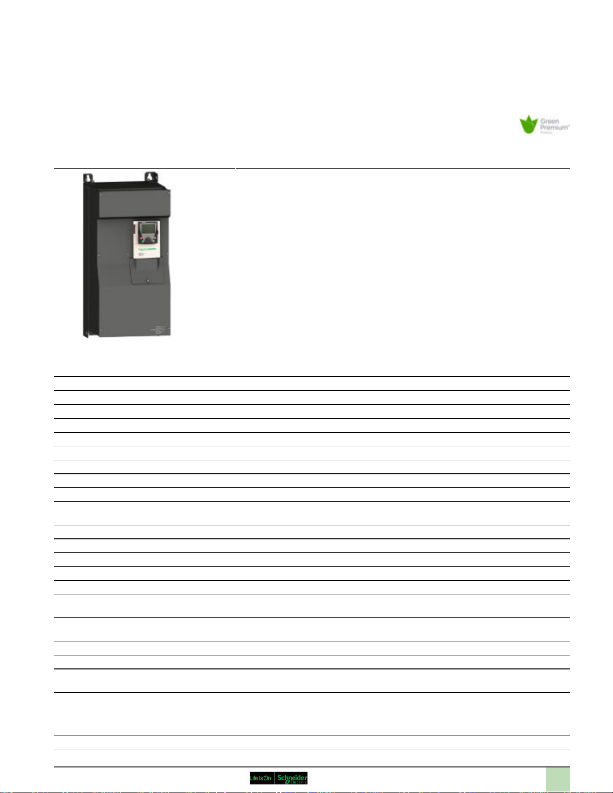
ATV71HC13N4
variable speed drive ATV71 - 132kW-200HP 480V - EMC filter-graphic terminal
Main
Range of product Altivar 71
Product or component type Variable speed drive
Product specific application Complex, high-power machines
Component name ATV71
Motor power kW 132 kW at 380...480 V 3 phases
Motor power hp 200 hp at 380...480 V 3 phases
Motor cable length
[Us] rated supply voltage 380...480 V (- 15...10 %)
Network number of phases 3 phases
Line current 192 A for 480 V 3 phases 132 kW / 200 hp
EMC filter Integrated
Assembly style With heat sink
Variant Reinforced version
Apparent power 157.3 kVA at 380 V 3 phases 132 kW / 200 hp
Prospective line Isc <= 35 kA, 3 phases
Nominal output current 259 A at 2.5 kHz 380 V 3 phases 132 kW / 200 hp
Maximum transient current 388 A for 60 s 3 phases 132 kW / 200 hp
Output frequency 0.1...500 Hz
Nominal switching frequency 2.5 kHz
Switching frequency 2.5...8 kHz adjustable
Asynchronous motor control profile ENA (Energy adaptation) system for unbalanced loads
Type of polarization No impedance for Modbus
239 A for 380 V 3 phases 132 kW / 200 hp
259 A at 2.5 kHz 460 V 3 phases 132 kW / 200 hp
427 A for 2 s 3 phases 132 kW / 200 hp
2.5...8 kHz with derating factor
Flux vector control (FVC) with sensor (current vector)
Sensorless flux vector control (SFVC) (voltage or current vector)
Voltage/Frequency ratio (2 or 5 points)
May 01, 2017
Disclaimer: This documentation is not intended as a substitute for and is not to be used for determining suitability or reliability of these products for specific user applications
1
Page 2

Complementary
Product destination Asynchronous motors
Supply voltage limits 323...528 V
Supply frequency 50...60 Hz (- 5...5 %)
Network frequency 47.5...63 Hz
Speed range 1...100 for asynchronous motor in open-loop mode, without speed feedback
Speed accuracy +/- 0.01 % of nominal speed for 0.2 Tn to Tn torque variation in closed-loop mode with encoder
Torque accuracy +/- 15 % in open-loop mode, without speed feedback
Transient overtorque 220 % of nominal motor torque +/- 10 % for 2 s
Braking torque <= 150 % with braking or hoist resistor
Synchronous motor control profile Vector control without speed feedback
Regulation loop Adjustable PI regulator
Motor slip compensation Adjustable
Local signalling 1 LED red presence of drive voltage
Output voltage <= power supply voltage
Insulation Electrical between power and control
Type of cable With a NEMA Type1 kit : 3-strand UL 508 cable at 40 °C, copper 75 °C PVC
Electrical connection AI1-/AI1+, AI2, AO1, R1A, R1B, R1C, R2A, R2B, LI1...LI6, PWR terminal 2.5 mm² / AWG 14
Tightening torque L1/R, L2/S, L3/T, U/T1, V/T2, W/T3 24 N.m / 212 lb.in
Supply Internal supply for reference potentiometer (1 to 10 kOhm), 10.5 V DC +/- 5 %, <= 10 mA for
Analogue input number 2
Analogue input type AI1-/Al1+ bipolar differential voltage +/- 10 V DC, input voltage 24 V max, resolution 11 bits + sign
Sampling duration AI1-/Al1+ 2 ms, +/- 0.5 ms for analog input(s)
Response time <= 100 ms in STO (Safe Torque Off)
Accuracy AI1-/Al1+ +/- 0.6 % for a temperature variation 60 °C
Linearity error AI1-/Al1+, AI2 +/- 0.15 % of maximum value
Analogue output number 1
Analogue output type AO1 software-configurable current 0...20 mA, impedance 500 Ohm, resolution 10 bits
Synchronous motors
1...50 for synchronous motor in open-loop mode, without speed feedback
1...1000 for asynchronous motor in closed-loop mode with encoder feedback
feedback
+/- 10 % of nominal slip for 0.2 Tn to Tn torque variation without speed feedback
+/- 5 % in closed-loop mode with encoder feedback
170 % of nominal motor torque +/- 10 % for 60 s every 10 minutes
30 % without braking resistor
Automatic whatever the load
Not available in voltage/frequency ratio (2 or 5 points)
Suppressable
With an IP21 or an IP31 kit : 3-strand IEC cable at 40 °C, copper 70 °C PVC
Without mounting kit : 1-strand IEC cable at 45 °C, copper 70 °C PVC
Without mounting kit : 1-strand IEC cable at 45 °C, copper 90 °C XLPE/EPR
L1/R, L2/S, L3/T, U/T1, V/T2, W/T3 terminal 2 x 120 mm²
PA, PB terminal 120 mm²
PC/-, PO, PA/+ terminal 2 x 120 mm²
PA, PB 24 N.m / 212 lb.in
PC/-, PO, PA/+ 24 N.m / 212 lb.in
AI1-/AI1+, AI2, AO1, R1A, R1B, R1C, R2A, R2B, LI1...LI6, PWR 0.6 N.m
overload and short-circuit protection
Internal supply, 24 V DC, voltage limits 21...27 V, <= 200 mA for overload and short-circuit protection
AI2 software-configurable current 0...20 mA, impedance 242 Ohm, resolution 11 bits
AI2 software-configurable voltage 0...10 V DC, input voltage 24 V max, impedance 30000 Ohm,
resolution 11 bits
Al2 2 ms, +/- 0.5 ms for analog input(s)
LI1...LI5 2 ms, +/- 0.5 ms for discrete input(s)
LI6 (if configured as logic input) 2 ms, +/- 0.5 ms for discrete input(s)
AO1 2 ms, tolerance +/- 0.5 ms for analog output(s)
R1A, R1B, R1C 7 ms, tolerance +/- 0.5 ms for discrete output(s)
R2A, R2B 7 ms, tolerance +/- 0.5 ms for discrete output(s)
AI2 +/- 0.6 % for a temperature variation 60 °C
AO1 +/- 1 % for a temperature variation 60 °C
AO1 +/- 0.2 %
2
Page 3

AO1 software-configurable logic output 10 V <= 20 mA
AO1 software-configurable voltage 0...10 V DC, impedance 470 Ohm, resolution 10 bits
Discrete output number 2
Discrete output type R1A, R1B, R1C configurable relay logic NO/NC, electrical durability 100000 cycles
Minimum switching current Configurable relay logic 3 mA at 24 V DC
Maximum switching current R1, R2 on resistive load, 5 A at 250 V AC, cos phi = 1,
Discrete input number 7
Discrete input type LI6 : switch-configurable 24 V DC with level 1 PLC, impedance: 3500 Ohm
Discrete input logic LI1...LI5 positive logic (source), < 5 V (state 0), > 11 V (state 0)
Acceleration and deceleration ramps Automatic adaptation of ramp if braking capacity exceeded, by using resistor
Braking to standstill By DC injection
Protection type Drive against exceeding limit speed
Insulation resistance > 1 mOhm at 500 V DC for 1 minute to earth
Frequency resolution Analog input 0.024/50 Hz
Communication port protocol CANopen
Type of connector 1 RJ45 for Modbus on front face
Physical interface 2-wire RS 485 for Modbus
Transmission frame RTU for Modbus
Transmission rate 20 kbps, 50 kbps, 125 kbps, 250 kbps, 500 kbps, 1 Mbps for CANopen
Data format 8 bits, 1 stop, even parity for Modbus on front face
Number of addresses 1...247 for Modbus
Method of access Slave for CANopen
Marking CE
Operating position Vertical +/- 10 degree
Height 1190 mm
Depth 377 mm
Width 340 mm
Product weight 80 kg
Functionality Full
Specific application Other applications
R2A, R2B configurable relay logic NO, electrical durability 100000 cycles
R1, R2 on resistive load, 5 A at 30 V DC, cos phi = 1,
R1, R2 on inductive load, 2 A at 250 V AC, cos phi = 0.4,
R1, R2 on inductive load, 2 A at 30 V DC, cos phi = 0.4,
PWR : safety input 24 V DC, impedance: 1500 Ohm conforming to ISO 13849-1 level d
LI1...LI5 : programmable 24 V DC with level 1 PLC, impedance: 3500 Ohm
LI6 : switch-configurable PTC probe 0...6, impedance: 1500 Ohm
LI1...LI5 negative logic (sink), > 16 V (state 0), < 10 V (state 0)
LI6 (if configured as logic input) positive logic (source), < 5 V (state 0), > 11 V (state 0)
LI6 (if configured as logic input) negative logic (sink), > 16 V (state 0), < 10 V (state 0)
Linear adjustable separately from 0.01 to 9000 s
S, U or customized
Drive against input phase loss
Drive break on the control circuit
Drive input phase breaks
Drive line supply overvoltage
Drive line supply undervoltage
Drive overcurrent between output phases and earth
Drive overheating protection
Drive overvoltages on the DC bus
Drive short-circuit between motor phases
Drive thermal protection
Motor motor phase break
Motor power removal
Motor thermal protection
Display unit 0.1 Hz
Modbus
1 RJ45 for Modbus on terminal
Male SUB-D 9 on RJ45 for CANopen
4800 bps, 9600 bps, 19200 bps, 38.4 Kbps for Modbus on terminal
9600 bps, 19200 bps for Modbus on front face
8 bits, odd even or no configurable parity for Modbus on terminal
1...127 for CANopen
3
Page 4

Option card CC-Link communication card
Controller inside programmable card
DeviceNet communication card
Ethernet/IP communication card
Fipio communication card
I/O extension card
Interbus-S communication card
Interface card for encoder
Modbus Plus communication card
Modbus TCP communication card
Modbus/Uni-Telway communication card
Overhead crane card
Profibus DP communication card
Profibus DP V1 communication card
Environment
Noise level 66 dB conforming to 86/188/EEC
Dielectric strength 3535 V DC between earth and power terminals
Electromagnetic compatibility Conducted radio-frequency immunity test conforming to IEC 61000-4-6 level 3
Standards EN 55011 class A group 2
Product certifications CSA
Pollution degree 2 conforming to EN/IEC 61800-5-1
IP degree of protection IP20
Vibration resistance 1.5 mm peak to peak (f = 3...10 Hz) conforming to EN/IEC 60068-2-6
Shock resistance 7 gn for 11 ms conforming to EN/IEC 60068-2-27
Relative humidity 5...95 % without condensation conforming to IEC 60068-2-3
Ambient air temperature for operation -10...50 °C without derating
Ambient air temperature for storage -25...70 °C
Operating altitude <= 1000 m without derating
5092 V DC between control and power terminals
Electrical fast transient/burst immunity test conforming to IEC 61000-4-4 level 4
Electrostatic discharge immunity test conforming to IEC 61000-4-2 level 3
Radiated radio-frequency electromagnetic field immunity test conforming to IEC 61000-4-3 level 3
Voltage dips and interruptions immunity test conforming to IEC 61000-4-11
1.2/50 µs - 8/20 µs surge immunity test conforming to IEC 61000-4-5 level 3
EN 61800-3 environments 1 category C3
EN 61800-3 environments 2 category C3
EN/IEC 61800-3
EN/IEC 61800-5-1
IEC 60721-3-3 class 3C2
UL Type 1
C-Tick
GOST
NOM 117
UL
3 conforming to UL 840
0.6 gn (f = 10...200 Hz) conforming to EN/IEC 60068-2-6
5...95 % without dripping water conforming to IEC 60068-2-3
1000...3000 m with current derating 1 % per 100 m
Offer Sustainability
Sustainable offer status Green Premium product
RoHS (date code: YYWW) Compliant - since 1002 - Schneider Electric declaration of conformity
Schneider Electric declaration of conformity
REACh Reference contains SVHC above the threshold - Go to CaP for more details
Go to CaP for more details
Product environmental profile Available
Product environmental
Product end of life instructions Available
End of life manual
4
Page 5

Contractual warranty
Warranty period 18 months
5
Page 6

Product data sheet
Dimensions Drawings
UL Type 1/IP 20 Drives
Dimensions with or without 1 Option Card (1)
ATV71HC13N4
Dimensions in mm
a b c G H K K1 K2 Ø
340 1190 377 285 920 150 75 30 11.5
Dimensions in in.
a b c G H K K1 K2 Ø
13.39 46.85 14.84 11.22 36.22 5.90 2.95 1.18 0.45
(1) Option cards: I/O extension cards, communication cards or "Controller Inside” programmable card.
Dimensions with 2 Option Cards (1)
Dimensions in mm
a c1 G H K K1 K2 Ø
340 392 285 920 150 75 30 11.5
Dimensions in in.
a c1 G H K K1 K2 Ø
13.39 15.43 11.22 36.22 5.90 2.95 1.18 0.45
(1) Option cards: I/O extension cards, communication cards or "Controller Inside” programmable card.
6
Page 7

Product data sheet
Mounting and Clearance
Mounting Recommendations
Clearance
ATV71HC13N4
X1 in mm X2 in mm X1 in in. X2 in in.
150 150 5.91 5.91
These drives can be mounted side by side, observing the following mounting recommendations:
7
Page 8

Product data sheet
ATV71HC13N4
Mounting and Clearance
Specific Recommendations for Mounting the Drive in an Enclosure
Ventilation
To ensure proper air circulation in the drive:
● Fit ventilation grilles.
● Ensure that there is sufficient ventilation. If there is not, install a forced ventilation unit with a filter. The openings and/or fans must provide a flow rate at least
● Use special filters with IP 54 protection.
● Remove the blanking cover from the top of the drive.
Dust and Damp Proof Metal Enclosure (IP 54)
The drive must be mounted in a dust and damp proof enclosure in certain environmental conditions: dust, corrosive gases, high humidity with risk
of condensation and dripping water, splashing liquid, etc.
This enables the drive to be used in an enclosure where the maximum internal temperature reaches 50°C.
8
Page 9

Product data sheet
ATV71HC13N4
Connections and Schema
Wiring Diagram Conforming to Standards EN 954-1 Category 1, IEC/EN 61508 Capacity SIL1, in Stopping Category
0 According to IEC/EN 60204-1
Three-Phase Power Supply with Upstream Breaking via Contactor
A1 ATV71 drive
KM1 Contactor
L1 DC choke
Q1 Circuit-breaker
Q2 GV2 L rated at twice the nominal primary current of T1
Q3 GB2CB05
S1, S2XB4B or XB5A pushbuttons
T1 100 VA transformer 220 V secondary
(1) Line choke (three-phase); mandatory for ATV71HC11Y…HC63Y drives (except when a special transformer is used (12-pulse)).
(2) For ATV71HC40N4 drives combined with a 400 kW motor, ATV71HC50N4 and ATV71HC40Y…HC63Y, refer to the power terminal connections diagram
(3) Fault relay contacts. Used for remote signalling of the drive status.
(4) Connection of the common for the logic inputs depends on the positioning of the SW1 switch. The above diagram shows the internal power supply switch
(5) There is no PO terminal on ATV71HC11Y…HC63Y drives.
(6) Optional DC choke for ATV71H•••M3, ATV71HD11M3X…HD45M3X, ATV71•075N4…•D75N4 and ATV71P•••N4Z drives. Connected in place of the strap
(7) Software-configurable current (0…20 mA) or voltage (0…10 V) analog input.
(8) Reference potentiometer.
All terminals are located at the bottom of the drive. Fit interference suppressors on all inductive circuits near the drive or connected on the same
circuit, such as relays, contactors, solenoid valves, fluorescent lighting, etc.
9
Page 10

Product data sheet
ATV71HC13N4
Connections and Schema
Wiring Diagram Conforming to Standards EN 954-1 Category 1, IEC/EN 61508 Capacity SIL1, in Stopping Category
0 According to IEC/EN 60204-1
Three-Phase Power Supply with Downstream Breaking via Switch Disconnector
A1 ATV71 drive
L1 DC choke
Q1 Circuit-breaker
Q2 Switch disconnector (Vario)
(1) Line choke (three-phase), mandatory for ATV71HC11Y…HC63Y drives (except when a special transformer is used (12-pulse)).
(2) For ATV71HC40N4 drives combined with a 400 kW motor, ATV71HC50N4 and ATV71HC40Y…HC63Y, refer to the power terminal connections diagram.
(3) Fault relay contacts. Used for remote signalling of the drive status.
(4) Connection of the common for the logic inputs depends on the positioning of the SW1 switch. The above diagram shows the internal power supply switched
(5) There is no PO terminal on ATV71HC11Y…HC63Y drives.
(6) Optional DC choke for ATV71H•••M3, ATV71HD11M3X…HD45M3X, ATV71•075N4…•D75N4 and ATV71P•••N4Z drives. Connected in place of the strap be
(7) Software-configurable current (0…20mA) or voltage (0…10V) analog input.
(8) Reference potentiometer.
All terminals are located at the bottom of the drive. Fit interference suppressors on all inductive circuits near the drive or connected on the same
circuit, such as relays, contactors, solenoid valves, fluorescent lighting, etc.
10
Page 11

Product data sheet
ATV71HC13N4
Connections and Schema
Wiring Diagram Conforming to Standards EN 954-1 Category 3, IEC/EN 61508 Capacity SIL2, in Stopping Category
0 According to IEC/EN 60204-1
Three-Phase Power Supply, Low Inertia Machine, Vertical Movement
A1 ATV71 drive
A2 Preventa XPS AC safety module for monitoring emergency stops and switches. One safety module can manage the “Power Removal” function for severa
F1 Fuse
L1 DC choke
Q1 Circuit-breaker
S1 Emergency stop button with 2 contacts
S2 XB4 B or XB5 A pushbutton
(1) Power supply: 24Vdc or Vac, 48Vac, 115Vac, 230Vac.
(2) S2: resets XPS AC module on power-up or after an emergency stop. ESC can be used to set external starting conditions.
(3) Requests freewheel stopping of the movement and activates the “Power Removal” safety function.
(4) Line choke (three-phase), mandatory for and ATV71HC11Y…HC63Y drives (except when a special transformer is used (12-pulse)).
(5) The logic output can be used to signal that the machine is in a safe stop state.
(6) For ATV71HC40N4 drives combined with a 400 kW motor, ATV71HC50N4 and ATV71HC40Y…HC63Y, refer to the power terminal connections diagram
(7) Fault relay contacts. Used for remote signalling of the drive status.
(8) Connection of the common for the logic inputs depends on the positioning of the SW1 switch. The above diagram shows the internal power supply switch
(9) Standardized coaxial cable, type RG174/U according to MIL-C17 or KX3B according to NFC93-550, external diameter 2.54mm /0.09in., maximum leng
(10) There is no PO terminal on ATV71HC11Y…HC63Y drives.
(11) Optional DC choke for ATV71H•••M3, ATV71HD11M3X…HD45M3X, ATV71•075N4…•D75N4 and ATV71P•••N4Z drives. Connected in place of the strap
(12) Software-configurable current (0…20mA) or voltage (0…10V) analog input.
(13) Reference potentiometer.
All terminals are located at the bottom of the drive. Fit interference suppressors on all inductive circuits near the drive or connected on the same
circuit, such as relays, contactors, solenoid valves, fluorescent lighting, etc.
11
Page 12

Product data sheet
ATV71HC13N4
Connections and Schema
Wiring Diagram Conforming to Standards EN 954-1 Category 3, IEC/EN 61508 Capacity SIL2, in Stopping Category
1 According to IEC/EN 60204-1
Three-Phase Power Supply, High Inertia Machine
A1 ATV71 drive
A2 (5)Preventa XPS ATE safety module for monitoring emergency stops and switches. One safety module can manage the "Power Removal” safety function for s
F1 Fuse
L1 DC choke
Q1 Circuit-breaker
S1 Emergency stop button with 2 N/C contacts
S2 Run button
(1) Power supply: 24Vdc or Vac, 115Vac, 230Vac.
(2) Requests controlled stopping of the movement and activates the “Power Removal” safety function.
(3) Line choke (three-phase), mandatory for ATV71HC11Y…HC63Y drives (except when a special transformer is used (12-pulse)).
(4) S2: resets XPSATE module on power-up or after an emergency stop. ESC can be used to set external starting conditions.
(5) For stopping times requiring more than 30 seconds in category 1, use a Preventa XPS AV safety module which can provide a maximum time delay of 300 se
(6) The logic output can be used to signal that the machine is in a safe state.
(7) For ATV71HC40N4 drives combined with a 400 kW motor, ATV71HC50N4 and ATV71HC40Y…HC63Y, refer to the power terminal connections diagram.
(8) Fault relay contacts. Used for remote signalling of the drive status.
(9) Connection of the common for the logic inputs depends on the positioning of the SW1 switch. The above diagram shows the internal power supply switched
(10) Standardized coaxial cable, type RG174/U according to MIL-C17 or KX3B according to NFC93-550, external diameter 2.54mm/0.09in., maximum length
(11) Logic inputs LI1 and LI2 must be assigned to the direction of rotation: LI1 in the forward direction and LI2 in the reverse direction.
(12) There is no PO terminal on ATV71HC11Y…HC63Y drives.
(13) Optional DC choke for ATV71H•••M3, ATV71HD11M3X…HD45M3X, ATV71•075N4…•D75N4 and ATV71P•••N4Z drives. Connected in place of the strap be
(14) Software-configurable current (0…20 mA) or voltage (0…10 V) analog input.
(15) Reference potentiometer.
All terminals are located at the bottom of the drive. Fit interference suppressors on all inductive circuits near the drive or connected on the same
circuit, such as relays, contactors, solenoid valves, fluorescent lighting, etc.
12
Page 13

Product data sheet
ATV71HC13N4
Performance Curves
Derating Curves
The derating curves for the drive nominal current (In) depend on the temperature and the switching frequency. For intermediate temperatures
(e.g. 55°C), interpolate between 2 curves.
X Switching frequency
13
 Loading...