

Page 1

The information provided in this documentation contains general descriptions and/or technical characteristics of the performance of the products contained herein.
This documentation is not intended as a substitute for and is not to be used for determining suitability or reliability of these products for specific user applications.
It is the duty of any such user or integrator to perform the appropriate and complete risk analysis, evaluation and testing of the products with respect to the relevant specific application or use thereof.
Neither Schneider Electric Industries SAS nor any of its affiliates or subsidiaries shall be responsible or liable for misuse of the information contained herein.
Product data sheet
Characteristics
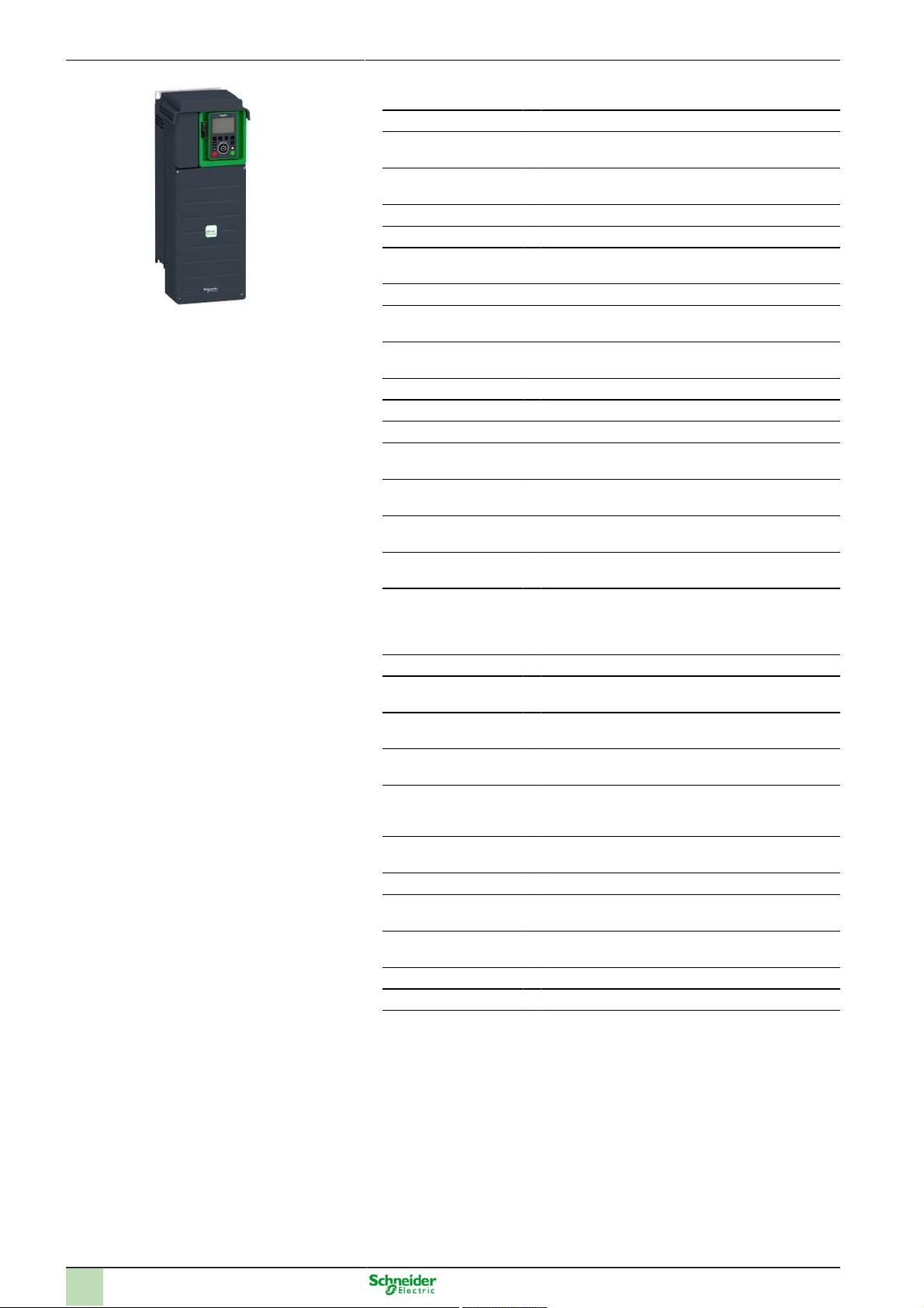
ATV630D18N4
variable speed drive ATV630 - 18.5kW/25HP -
380...480V - IP21/UL type 1
Dec 15, 2016
1
Page 2
Main
Range of product Altivar Process ATV600
Product or component
type
Product specific appli-
cation
Device short name ATV630
Variant Standard version
Product destination Asynchronous motors
Mounting mode Wall mount
EMC filter Integrated EN/IEC 61800-3 category C2 50 m
IP degree of protection IP21 IEC 61800-5-1
Degree of protection UL type 1 UL 508C
Type of cooling Forced convection
Supply frequency 50...60 Hz - 5...5 %
Network number of
phases
[Us] rated supply volt-
age
Motor power kW 18.5 kW normal duty
Motor power hp 25 hp normal duty
Line current 33.4 A 380 V normal duty
Prospective line Isc 50 kA
Apparent power 24 kVA 480 V normal duty
Continuous output current
Maximum transient current
Asynchronous motor
control profile
Synchronous motor
control profile
Output frequency 0.0001...0.5 kHz
Nominal switching fre-
quency
Switching frequency 2...12 kHz adjustable
Safety function STO (safe torque off) SIL 3
Discrete input logic 16 preset speeds
Variable speed drive
Process and utilities
Synchronous motors
Integrated EN/IEC 61800-3 category C3 150 m
IP21 IEC 60529
3 phases
380...480 V - 15...10 %
15 kW heavy duty
20 hp heavy duty
28.9 A 480 V normal duty
27.7 A 380 V heavy duty
24.4 A 480 V heavy duty
20.3 kVA 480 V heavy duty
39.2 A 4 kHz normal duty
31.7 A 4 kHz heavy duty
43.1 A 60 s normal duty
47.6 A 60 s heavy duty
Constant torque standard
Variable torque standard
Optimized torque mode
Permanent magnet motor
4 kHz
4...12 kHz with derating factor
2
Page 3

Communication port
protocol
Option card Communication module Profibus DP V1 slot A
Ethernet
Modbus serial
Modbus TCP
Communication module Profinet slot A
Communication module DeviceNet slot A
Communication module Modbus TCP/EtherNet/IP
slot A
Communication module CANopen daisy chain RJ45
slot A
Communication module CANopen SUB-D 9 slot A
Communication module CANopen screw terminals
slot A
Digital and analog I/O extension module slot A/slot B
Output relay extension module slot A/slot B
Communication module Ethernet IP/Modbus TCP/
MD-Link slot A
Complementary
Output voltage <= power supply voltage
Permissible temporary current boost 1.1 x In 60 s normal duty
Motor slip compensation Adjustable
Acceleration and deceleration ramps Linear adjustable separately from 0.01 to 9000 s
Braking to standstill By DC injection
Protection type Thermal protection motor
Frequency resolution 0.1 Hz display unit
Electrical connection Removable screw terminals 0.5...1.5 mm² AWG 20...AWG 16 control
Type of connector RJ45 Ethernet/Modbus TCP on the remote graphic terminal
Physical interface 2-wire RS 485 Modbus serial
Transmission frame RTU Modbus serial
Transmission rate 10/100 Mbit/s Ethernet IP/Modbus TCP
Exchange mode Half duplex, full duplex, autonegotiation Ethernet/Modbus TCP
Data format 8 bits, configurable odd, even or no parity Modbus serial
Type of polarization No impedance Modbus serial
Number of addresses 1...247 Modbus serial
Method of access Slave Modbus TCP
Supply External supply for digital inputs 24 V DC 19...30 V <= 1.25 mA overload and
1.5 x In 60 s heavy duty
Automatic whatever the load
Can be suppressed
Not available in permanent magnet motor law
S, U or customized
Safe torque off motor
Motor phase break motor
Thermal protection drive
Safe torque off drive
Overheating drive
Overcurrent between output phases and earth drive
Overload of output voltage drive
Short-circuit protection drive
Motor phase break drive
Overvoltages on the DC bus drive
Line supply overvoltage drive
Line supply undervoltage drive
Line supply phase loss drive
Overspeed drive
Break on the control circuit drive
0.012/50 Hz analog input
Screw terminal 10...16 mm² AWG 8...AWG 6 line side
Screw terminal 10...16 mm² AWG 8...AWG 6 motor
RJ45 Modbus serial on the remote graphic terminal
4.8, 9.6, 19.2, 38.4 kbit/s Modbus serial
short-circuit protection
Internal supply for reference potentiometer (1 to 10 kOhm) 10.5 V DC +/- 5 % <=
10 mA overload and short-circuit protection
Internal supply for digital inputs and STO 24 V DC 21...27 V <= 200 mA overload
and short-circuit protection
3
Page 4

Local signalling 3 LEDs local diagnostic
Width 211 mm
Height 546 mm
Depth 232 mm
Product weight 14.2 kg
Analogue input number 3
Analogue input type Software-configurable voltage AI1, AI2, AI3 0...10 V DC 30 kOhm 12 bits
Discrete input number 8
Discrete input type Programmable DI1...DI6 24 V DC <= 30 V 3.5 kOhm
Input compatibility Level 1 PLC EN/IEC 61131-2 DI1...DI6 discrete input
Discrete input logic Positive logic (source) DI1...DI6 < 5 V > 11 V
Analogue output number 2
Analogue output type Software-configurable voltage AO1, AO2 0...10 V DC 470 Ohm 10 bits
Sampling duration 2 ms +/- 0.5 ms DI1...DI4 discrete input
Accuracy +/- 0.6 % AI1, AI2, AI3 for a temperature variation 60 °C analog input
Linearity error +/- 0.15 % of maximum value analog input AI1, AI2, AI3
Relay output number 3
Relay output type Configurable relay logic R1 fault relay NO/NC 100000 cycles
Refresh time 5 ms +/- 0.5 ms R1, R2, R3 relay output
Minimum switching current 5 mA 24 V DC R1, R2, R3 relay output
Maximum switching current 3 A 250 V AC resistive 1 R1, R2, R3 relay output
Isolation Between power and control terminals
Functionality Full
Specific application Utility
IP degree of protection IP21
3 LEDs dual colour embedded communication status
4 LEDs dual colour communication module status
1 LED red presence of voltage
Software-configurable current AI1, AI2, AI3 0...20 mA 250 Ohm 12 bits
Programmable as pulse input DI5, DI6 0...30 kHz 24 V DC <= 30 V
Safe torque off STOA, STOB 24 V DC <= 30 V > 2.2 kOhm
Level 1 PLC IEC 65A-68 DI5, DI6 discrete input
Level 1 PLC EN/IEC 61131-2 STOA, STOB discrete input
Negative logic (sink) DI1...DI6 > 16 V < 10 V
Positive logic (source) DI5, DI6 < 0.6 V > 2.5 V
Positive logic (source) STOA, STOB < 5 V > 11 V
Software-configurable current AO1, AO2 0...20 mA 10 bits
5 ms +/- 1 ms DI5, DI6 discrete input
5 ms +/- 0.1 ms AI1, AI2, AI3 analog input
10 ms +/- 1 ms AO1 analog output
+/- 1 % AO1, AO2 for a temperature variation 60 °C analog output
+/- 0.2 % analog output AO1, AO2
Configurable relay logic R2 sequence relay NO 100000 cycles
Configurable relay logic R3 sequence relay NO 100000 cycles
3 A 30 V DC resistive 1 R1, R2, R3 relay output
2 A 250 V AC inductive 0.4 7 ms R1, R2, R3 relay output
2 A 30 V DC inductive 0.4 7 ms R1, R2, R3 relay output
Environment
Insulation resistance > 1 mOhm 500 V DC for 1 minute to earth
Noise level 59.5 dB 86/188/EEC
Power dissipation in W 67 W natural convection 380 V 4 kHz
Volume of cooling air 215 m3/h
Operating position Vertical +/- 10 degree
THDI <= 48 % from 80...100 % of load IEC 61000-3-12
Electromagnetic compatibility Electrostatic discharge immunity test level 3 IEC 61000-4-2
Pollution degree 2 EN/IEC 61800-5-1
4
460 W forced convection 380 V 4 kHz
Radiated radio-frequency electromagnetic field immunity test level 3 IEC
61000-4-3
Electrical fast transient/burst immunity test level 4 IEC 61000-4-4
1.2/50 µs - 8/20 µs surge immunity test level 3 IEC 61000-4-5
Conducted radio-frequency immunity test level 3 IEC 61000-4-6
Page 5

Vibration resistance 1.5 mm peak to peak 2...13 Hz IEC 60068-2-6
Shock resistance 15 gn 11 ms IEC 60068-2-27
Relative humidity 5...95 % without condensation IEC 60068-2-3
Ambient air temperature for operation -15...50 °C without derating
Ambient air temperature for storage -40...70 °C
Operating altitude <= 1000 m without derating
Environmental characteristic Chemical pollution resistance class 3C3 EN/IEC 60721-3-3
Standards UL 508C
Product certifications ATEX INERIS
Marking CE
1 gn 13...200 Hz IEC 60068-2-6
50...60 °C with derating factor
1000...4800 m with current derating 1 % per 100 m
Dust pollution resistance class 3S3 EN/IEC 60721-3-3
EN/IEC 61800-3
EN/IEC 61800-3 environment 1 category C2
EN/IEC 61800-3 environment 2 category C3
EN/IEC 61800-5-1
IEC 61000-3-12
IEC 60721-3
IEC 61508
IEC 13849-1
ATEX zone 2/22
CSA
TÜV
UL
REACH
DNV-GL
Offer Sustainability
Sustainable offer status Green Premium product
RoHS (date code: YYWW)
REACh
Product environmental profile
Product end of life instructions
Compliant - since 1426 - Schneider Electric declaration of conformity
Reference contains SVHC above the threshold - go to CaP for more details
Available Download Product Environmental
Available Download End Of Life Manual
5
Page 6

Product data sheet
Dimensions Drawings
Dimensions
Views: Front - Left
ATV630D18N4
Drives Without IP21 Top Cover
Views: Left - Rear
6
Page 7

Product data sheet
Mounting and Clearance
Clearances
ATV630D18N4
X1 X2 X3
≥ 100 mm (3.94 in.) ≥ 100 mm (3.94 in.) ≥ 10 mm (0.39 in.)
Mounting Types
Mounting Type A: Individual IP21
a ≥ 100 mm (3.94 in.)
7
Page 8

Mounting Type B: Side by Side IP20
Mounting Type C: Individual IP20
a ≥ 0
8
Page 9

Product data sheet
ATV630D18N4
Connections and Schema
Single or Three-Phase Power Supply with Upstream Breaking via Line Contactor
Connection diagrams conforming to standards EN 954-1 category 1 and IEC/EN 61508 capacity SIL1, stopping category 0 in accordance
with standard IEC/EN 60204-1
(1) Use digital output R1 set to operating state Fault to switch Off the product once an error is detected.
A1 : Drive
KM1 Line Contactor
Q2,
Circuit breakers
Q3 :
S1,
Pushbuttons
S2 :
T1 : Transformer for control part
Single or Three-Phase Power Supply with Downstream Breaking via Switch Disconnector
Connection diagrams conforming to standards EN 954-1 category 1 and IEC/EN 61508 capacity SIL1, stopping category 0 in accordance
with standard IEC/EN 60204-1
(1) Use digital output R1 set to operating state Fault to switch Off the product once an error is detected.
A1 : Drive
Q1 : Switch disconnector
Control Block Wiring Diagram
9
Page 10

(1) Safe Torque Off
(2) Analog Output
(3) Digital Input
(4) Reference potentiometer
(5) Analog Input
A1 : ATV6.. Drive
R1A,
Fault relay
R1B,
R1C :
R2A,
Sequence relay
R2C :
R3A,
Sequence relay
R3C :
Sensor Connection
It is possible to connect either 1 or 3 sensors on terminals AI2 or AI3.
Sink / Source Switch Configuration
The switch is used to adapt the operation of the logic inputs to the technology of the programmable controller outputs.
● Set the switch to Source (factory setting) if using PLC outputs with PNP transistors.
● Set the switch to Ext if using PLC outputs with NPN transistors.
Switch Set to SRC (Source) Position Using the Output Power Supply for the Digital Inputs
10
Page 11

Switch Set to SRC (Source) Position and Use of an External Power Supply for the DIs
Switch Set to SK (Sink) Position Using the Output Power Supply for the Digital Inputs
Switch Set to EXT Position Using an External Power Supply for the DIs
11
Page 12

Product data sheet
Performance Curves
Derating Curves
ATV630D18N4
40 °C (104 °F) - Mounting type A, B and C
50 °C (122 °F) - Mounting type A, B and C
60 °C (140 °F) - Mounting type B and C
In : Nominal Drive Current
SF : Switching Frequency
12
 Loading...