

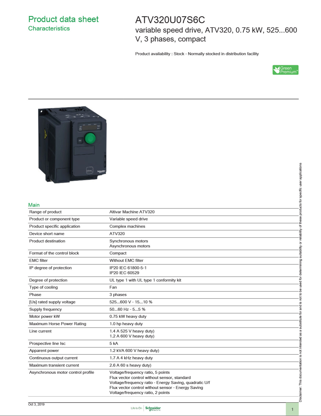
Page 1
Page 2

Synchronous motor control profile Vector control without sensor
Speed drive output frequency 0.1…599Hz
Nominal switching frequency 4 kHz
Switching frequency 2...16 kHz adjustable
Safety function STO (safe torque off) SIL 3
Communication port protocol Modbus serial
Optional communication modules communication module, CANopen daisy chain RJ45
4...16 kHz with derating factor
SLS (safe limited speed)
SS1 (safe stop 1)
SMS (safe maximum speed)
GDL (guard door locking)
CANopen
communication module, CANopen SUB-D 9
communication module, CANopen open style terminal block
communication module, EtherCAT RJ45
communication module, DeviceNet
communication module, Ethernet/IP
communication module, Profibus DP V1
communication module, Profinet
communication module, Ethernet Powerlink
Complementary
Variant Standard version
Output voltage <= power supply voltage
Permissible temporary current boost 1.5 x In 60 s heavy duty)
Speed range 1…100 asynchronous motor in open-loop mode
Speed accuracy +/- 10 % of nominal slip 0.2 Tn to Tn
Torque accuracy +/- 15 %
Transient overtorque 170…200% of nominal motor torque
Braking torque <= 170 % 60 s with braking resistor
Regulation loop Adjustable PID regulator
Motor slip compensation Automatic whatever the load
Acceleration and deceleration ramps Linear
Braking to standstill By DC injection
Protection type Input phase breaks drive
Frequency resolution Display unit 0.1 Hz
Electrical connection Screw terminal 0.5...1.5 mm², AWG 20...AWG 16 control)
Connector type 1 RJ45 on terminal)Modbus/CANopen
Physical interface 2-wire RS 485 Modbus/CANopen
Transmission frame RTU Modbus serial
Transmission rate 4.8, 9.6, 19.2, 38.4 kbit/s Modbus serial
Data format 8 bits, configurable odd, even or no parity Modbus serial
Type of polarization No impedance Modbus serial
Number of addresses 1…127 CANopen
Adjustable 0...300 %
Not available in voltage/frequency ratio (2 or 5 points)
U
S
CUS
Ramp switching
Deceleration ramp adaptation
Deceleration ramp automatic stop DC injection
Overcurrent between output phases and earth drive
Overheating protection drive
Short-circuit between motor phases drive
Thermal protection drive
Analog input 0.012/50 Hz
Screw terminal 4...6 mm², AWG 12...AWG 10 motor/braking resistor)
Screw terminal 4...6 mm², AWG 12...AWG 10 power supply)
50 kbps, 125 kbps, 250 kbps, 500 kbps, 1 Mbps CANopen
1…247 Modbus serial
2
Page 3

Method of access Slave CANopen
Supply Internal supply for reference potentiometer (1 to 10 kOhm) 10.5 V DC +/- 5 %, <10mA overload and
Local signalling CANopen run 1 LED green)
Width 4.13in (105.0mm)
Height 5.59in (142.0mm)
Depth 6.22in (158.0mm)
Net weight 2.80lb(US) (1.27kg)
Analogue input number 3
Analogue input type AI1 voltage 0...10 V DC 30000 Ohm 10 bits
Discrete input number 7
Discrete input type Programmable (sink/source) DI1...DI4)24...30 V DC level 1 PLC
Discrete input logic Negative logic (sink) DI1...DI6), > 19 V, < 13 V
Analogue output number 1
Analogue output type AQ1 software-configurable current 0...20 mA 800Ohm 10 bits
Sampling duration 2ms AI1, AI2, AI3) - analog input
Accuracy +/- 0.2 % AI1, AI2, AI3 for a temperature of -10...60 °C analog input
Linearity error AI1, AI2, AI3 +/- 0.2...0.5 % of maximum value analog input
Discrete output number 3
Discrete output type Configurable relay logic R1A, R1B, R1C) NO/NC - 100000cycles
Refresh time Logic input DI1...DI6)8 ms +/- 0.7 ms)
Minimum switching current Relay output R1, R2 5mA 24 V DC
Maximum switching current Relay output R1 resistive, cos phi = 1 3A 250 V AC
Specific application Machinery
Motor power range 0.75…1.1kW 525…600V 3 phases
Motor starter type Variable speed drive
short-circuit protection
CANopen error 1 LED red)
Drive fault 1 LED red)
AI2 bipolar differential voltage +/- 10 V DC 30000 Ohm 10 bits
AI3 current 0...20 mA (or 4-20 mA, x-20 mA, 20-x mA or other patterns by configuration) 250 Ohm 10
bits
Programmable as pulse input 20 kpps DI5)24...30 V DC level 1 PLC
Switch-configurable PTC probe DI6)24...30 V DC
Safe torque off STO)24...30 V DC - 1500 Ohm
Positive logic (source) DI1...DI6), < 5 V, > 11 V
AQ1 software-configurable voltage 0...10 V 470Ohm 10 bits
2ms AQ1) - analog output
+/- 0.5 % AI1, AI2, AI3 for a temperature of 25 °C analog input
+/- 1 % AQ1 for a temperature of 25 °C analog output
+/- 2 % AQ1 for a temperature of -10...60 °C analog output
AQ1 +/- 0.3 % analog output
Configurable relay logic R2A, R2B) NO - 100000cycles
Logic LO)
Relay output R1A, R1B, R1C)2 ms
Relay output R2A, R2C)2 ms
Relay output R1 resistive, cos phi = 1 4A 30 V DC
Relay output R1, R2 inductive, cos phi = 0.4 2A 250 V AC
Relay output R1, R2 inductive, cos phi = 0.4 2A 30 V DC
Relay output R2 resistive, cos phi = 1 5A 250 V AC
Relay output R2 resistive, cos phi = 1 5A 30 V DC
Environment
Isolation Between power and control terminals
Insulation resistance > 1 MOhm 500 V DC for 1 minute to earth
Noise level 51dB 86/188/EEC
Power dissipation in W Fan 31.0W 525 V 4 kHz
Volume of cooling air 4755.18Gal/hr(US) (18.0m3/h)
Operating position Vertical +/- 10 degree
Electromagnetic compatibility 1.2/50 µs - 8/20 µs surge immunity test level 3 IEC 61000-4-5
Conducted radio-frequency immunity test level 3 IEC 61000-4-6
Electrical fast transient/burst immunity test level 4 IEC 61000-4-4
3
Page 4

Electrostatic discharge immunity test level 3 IEC 61000-4-2
Radiated radio-frequency electromagnetic field immunity test level 3 IEC 61000-4-3
Voltage dips and interruptions immunity test IEC 61000-4-11
Pollution degree 2 EN/IEC 61800-5-1
Vibration resistance 1 gn 13…200Hz)EN/IEC 60068-2-6
Shock resistance 15 gn 11ms EN/IEC 60068-2-27
Relative humidity 5…95% without condensation IEC 60068-2-3
Ambient air temperature for operation 14…122°F (-10…50°C) without
Ambient air temperature for storage -13…158°F (-25…70°C)
Operating altitude <= 3280.84 ft (1000 m) without
Environmental characteristic Chemical pollution resistance class 3C3 EN/IEC 60721-3-3
Standards EN/IEC 61800-3
Product certifications CE
Marking CE
3 EN/IEC 61800-5-1
1.5 mm peak to peak 2…13Hz)EN/IEC 60068-2-6
5…95% without dripping water IEC 60068-2-3
122…140°F (50…60°C) with derating factor
3280.84...6561.68 ft (1000...2000 m) with current derating 1 % per 100 m
Dust pollution resistance class 3S2 EN/IEC 60721-3-3
Environment 1 category C2 EN/IEC 61800-3
Environment 2 category C3 EN/IEC 61800-3
EN/IEC 61800-5-1
IEC 61000-3-12
IEC 60721-3
IEC 61508
IEC 13849-1
ATEX
UL 508
CSA 22-2
NOM
EAC
RCM
KC
REACH
UL
CSA
EAC
RCM
Ordering and shipping details
Category 22152 - ATV320/ATV312/ATV32 (.25 THRU 7.5HP)
Discount Schedule CP4B
GTIN 00785901626688
Package weight(Lbs) 1.50kg (3.3lb(US))
Returnability Yes
Country of origin ID
Offer Sustainability
Sustainable offer status Green Premium product
REACh Regulation REACh Declaration
EU RoHS Directive Pro-active compliance (Product out of EU RoHS legal scope)
Mercury free Yes
RoHS exemption information Yes
China RoHS Regulation China RoHS declaration
Environmental Disclosure Product Environmental Profile
Circularity Profile End of Life Information
WEEE The product must be disposed on European Union markets following specific waste collection and
EU RoHS Declaration
never end up in rubbish bins.
4
Page 5

Product data sheet
ATV320U07S6C
Dimensions Drawings
Dimensions
Right View, Front View and Front View with EMC Plate
5
Page 6

Product data sheet
ATV320U07S6C
Mounting and Clearance
Mounting Types
Mounting Type A: Individual with Ventilation Cover
Only Possible at Ambient Temperature Less or Equal to 50 °C (122 °F)
Mounting Type B: Side by Side, Ventilation Cover Removed
Mounting Type C: Individual, Ventilation Cover Removed
For Operation at Ambient Temperature Above 50 °C (122 °F)
6
Page 7

Product data sheet
ATV320U07S6C
Connections and Schema
Connection Diagrams
Diagram with Line Contactor
Connection diagrams conforming to standards ISO13849 category 1 and IEC/EN 61508 capacity SIL1, stopping category 0 in accordance with
standard IEC/EN 60204-1.
(1) Line choke (if used)
(2) Fault relay contacts, for remote signaling of drive status
Diagram with Switch Disconnect
Connection diagrams conforming to standards EN 954-1 category 1 and IEC/EN 61508 capacity SIL1, stopping category 0 in accordance with
standard IEC/EN 60204-1.
(1) Line choke (if used)
(2) Fault relay contacts, for remote signaling of drive status
7
Page 8

Product data sheet
Connections and Schema
Control Connection Diagram in Source Mode
ATV320U07S6C
(1) Analog output
(2) Analog inputs
(3) Reference potentiometer (10 kOhm maxi)
(4) Digital inputs
8
Page 9

Product data sheet
ATV320U07S6C
Connections and Schema
Digital Inputs Wiring
The logic input switch (SW1) is used to adapt the operation of the logic inputs to the technology of the programmable controller outputs.
Switch SW1 set to “Source” position and use of the output power supply for the DIs.
Switch SW1 set to “Source” position and use of an external power supply for the DIs.
Switch SW1 set to “Sink Int” position and use of the output power supply for the DIs.
Switch SW1 set to “Sink Ext” position and use of an external power supply for the DIs.
9
Page 10

Product data sheet
Performance Curves
Derating Curves
ATV320U07S6C
40°C (104°F) - Mounting type A, B and C
50°C (122°F) - Mounting type C
In : Nominal Drive Current
SF : Switching Frequency
60°C (122°F) - Mounting type C
10
 Loading...