


31002674 4/2010
Momentum M1 Processor Adapter and Option Adapter
User Guide
4/2010
www.schneider-electric.com
31002674.10

© 2010 Schneider Electric. All rights reserved.
2 31002674 4/2010

Table of Contents
Safety Information . . . . . . . . . . . . . . . . . . . . . . . . . . . . . . 11
About the Book . . . . . . . . . . . . . . . . . . . . . . . . . . . . . . . . . 13
Part I Getting Started with Momentum Components . . . . 15
Chapter 1 Overview of Momentum M1 Processor Adapters . . . . . 17
1.1 Introducing the M1 Processor Adapters . . . . . . . . . . . . . . . . . . . . . . . . . . 18
Front Panel Illustration (M1 Processor Adapters) . . . . . . . . . . . . . . . . . . . 19
Overview of Ports (M1 Processor Adapters) . . . . . . . . . . . . . . . . . . . . . . . 20
Memory and Performance Characteristics of M1 Processor Adapters . . . 22
Power Supply for M1 Processor Adapters . . . . . . . . . . . . . . . . . . . . . . . . 24
1.2 Features of Each M1 Processor Adapter . . . . . . . . . . . . . . . . . . . . . . . . . 25
171 CCS 700 00 (M1 Processor Adapter). . . . . . . . . . . . . . . . . . . . . . . . . 26
171 CCS 700 10 (M1 Processor Adapter). . . . . . . . . . . . . . . . . . . . . . . . . 29
171 CCS 760 00 (M1 Processor Adapter). . . . . . . . . . . . . . . . . . . . . . . . . 32
171 CCC 760 10 (M1 Processor Adapter) . . . . . . . . . . . . . . . . . . . . . . . . 35
171 CCS 780 00 (M1 Processor Adapter). . . . . . . . . . . . . . . . . . . . . . . . . 38
171 CCC 780 10 (M1 Processor Adapter) . . . . . . . . . . . . . . . . . . . . . . . . 41
171 CCC 960 20 (M1 Processor Adapter) . . . . . . . . . . . . . . . . . . . . . . . . 44
171 CCC 960 30 M1 Processor Adapter. . . . . . . . . . . . . . . . . . . . . . . . . . 48
171 CCC 980 20 (M1 Processor Adapter) . . . . . . . . . . . . . . . . . . . . . . . . 52
171 CCC 980 30 (M1 Processor Adapter) . . . . . . . . . . . . . . . . . . . . . . . . 56
Chapter 2 Overview of Momentum Option Adapters . . . . . . . . . . . 61
2.1 Introducing the Momentum Option Adapters. . . . . . . . . . . . . . . . . . . . . . . 62
Basic Features of Option Adapters . . . . . . . . . . . . . . . . . . . . . . . . . . . . . . 62
2.2 Serial Option Adapter (Momentum). . . . . . . . . . . . . . . . . . . . . . . . . . . . . . 63
Front Panel Components of Momentum Serial Option Adapter . . . . . . . . 64
Specifications of the Momentum Serial Option Adapter . . . . . . . . . . . . . . 66
2.3 Modbus Plus Option Adapter . . . . . . . . . . . . . . . . . . . . . . . . . . . . . . . . . . 67
Front Panel Components of the Momentum Modbus Plus Option Adapter 68
Specifications of the Momentum Modbus Plus Option Adapter . . . . . . . . 70
2.4 Redundant Modbus Plus Option Adapter (A Momentum Component) . . . 71
Front Panel Components of the Momentum Redundant Modbus Plus
Option Adapter . . . . . . . . . . . . . . . . . . . . . . . . . . . . . . . . . . . . . . . . . . . . . 72
Specifications of the Momentum Redundant Modbus Plus Option Adapter 75
31002674 4/2010 3

Chapter 3 Assembling Momentum Components . . . . . . . . . . . . . . . 77
3.1 Assembling an M1 CPU with an I/O Base . . . . . . . . . . . . . . . . . . . . . . . . 78
Assembling a Processor Adapter onto an I/O Base. . . . . . . . . . . . . . . . . 79
Disassembling a Momentum Processor from an I/O Base . . . . . . . . . . . 82
3.2 Assembling an M1 CPU with a Momentum Option Adapter . . . . . . . . . . 84
Assembling an M1 Processor Adapter and a Momentum Option Adapter 85
Mounting the Assembled Adapters on the I/O Base . . . . . . . . . . . . . . . . 87
Disassembling a Momentum Module with an Option Adapter . . . . . . . . . 89
3.3 Installing Batteries in a Momentum Option Adapter. . . . . . . . . . . . . . . . . 92
Installation Guidelines . . . . . . . . . . . . . . . . . . . . . . . . . . . . . . . . . . . . . . . 92
3.4 Labeling the M1 CPU. . . . . . . . . . . . . . . . . . . . . . . . . . . . . . . . . . . . . . . . 95
Guidelines for Labeling the Momentum Processor Adapter . . . . . . . . . . 95
Part II Communication Ports on Momentum Components 97
Chapter 4 Using the Modbus Ports for Momentum Components. . 99
4.1 Modbus Port 1 (on Selected M1 Processor Adapters). . . . . . . . . . . . . . . 100
Modbus Port 1 (On Selected M1 Processor Adapters) . . . . . . . . . . . . . . 101
Cable Accessories for Modbus Port 1 on M1 Processor Adapters . . . . . 103
Pinouts for Modbus Port 1 on M1 Processor Adapters . . . . . . . . . . . . . . 104
4.2 Modbus Port 2 (On Selected Momentum Components) . . . . . . . . . . . . . 106
Modbus Port 2 (On Selected Momentum Components) . . . . . . . . . . . . . 107
Four-Wire Cabling Schemes for Modbus RS485 Networks Connecting
Momentum Components . . . . . . . . . . . . . . . . . . . . . . . . . . . . . . . . . . . . . 110
Two-Wire Cabling Schemes for Modbus RS485 Networks Connecting
Momentum Components . . . . . . . . . . . . . . . . . . . . . . . . . . . . . . . . . . . . . 113
Cable for Modbus RS485 Networks Connecting Momentum Components 115
Connectors for Modbus RS485 Networks Connecting Momentum
Components . . . . . . . . . . . . . . . . . . . . . . . . . . . . . . . . . . . . . . . . . . . . . . 118
Terminating Devices for Modbus RS485 Networks Connecting
Momentum Components . . . . . . . . . . . . . . . . . . . . . . . . . . . . . . . . . . . . . 119
Pinouts for Modbus RS485 Networks Connecting Momentum
Components . . . . . . . . . . . . . . . . . . . . . . . . . . . . . . . . . . . . . . . . . . . . . . 120
Chapter 5 Using the Modbus Plus Ports with Momentum
Components . . . . . . . . . . . . . . . . . . . . . . . . . . . . . . . . . . . . 127
Modbus Plus Features for Momentum. . . . . . . . . . . . . . . . . . . . . . . . . . . 128
Two Types of Modbus Plus Networks for Momentum Components . . . . 129
Standard Cabling Schemes . . . . . . . . . . . . . . . . . . . . . . . . . . . . . . . . . . . 130
Cluster Mode Cabling Schemes . . . . . . . . . . . . . . . . . . . . . . . . . . . . . . . 132
Cable Accessories for Modbus Plus Networks . . . . . . . . . . . . . . . . . . . . 136
Pinouts and Wiring Illustrations for Modbus Plus Networks with
Momentum Components . . . . . . . . . . . . . . . . . . . . . . . . . . . . . . . . . . . . . 138
Modbus Plus Addresses in Networks with Momentum Components. . . . 142
Peer Cop on Modbus Plus Networks with Momentum Components . . . . 144
4 31002674 4/2010

Chapter 6 Using the Ethernet Port on Selected M1 Processor
Adapters . . . . . . . . . . . . . . . . . . . . . . . . . . . . . . . . . . . . . . 147
Ethernet Port . . . . . . . . . . . . . . . . . . . . . . . . . . . . . . . . . . . . . . . . . . . . . . . 148
Network Design Considerations for M1 Ethernet Processors . . . . . . . . . . 149
Security Firewalls for Networks with M1 Ethernet Processors . . . . . . . . . 151
Cabling Schemes for Ethernet Networks with Momentum Components. . 152
Pinouts for Networks with Momentum Components . . . . . . . . . . . . . . . . . 153
Assigning Ethernet Address Parameters on M1 Ethernet Processors . . . 154
Using BOOTP Lite to Assign Address Parameters for Momentum
Components . . . . . . . . . . . . . . . . . . . . . . . . . . . . . . . . . . . . . . . . . . . . . . . 156
Reading Ethernet Network Statistics. . . . . . . . . . . . . . . . . . . . . . . . . . . . . 157
Description of Ethernet Network Statistics for Momentum Components. . 158
Chapter 7 Using the I/O Bus Port for Networks Momentum
Components . . . . . . . . . . . . . . . . . . . . . . . . . . . . . . . . . . . 161
I/O Bus Ports on Momentum Components . . . . . . . . . . . . . . . . . . . . . . . . 162
How I/O Bus Works with Momentum Components . . . . . . . . . . . . . . . . . . 163
Network Status Indication in the M1 Ethernet Module . . . . . . . . . . . . . . . 164
Guidelines for Momentum M1 I/OBus Networks . . . . . . . . . . . . . . . . . . . . 165
Cable Accessories for I/OBus Networks with Momentum Components . . 167
Pinouts for Momentum I/OBus Remote Bus Cables . . . . . . . . . . . . . . . . . 168
Part III Modsoft and Momentum Components. . . . . . . . . . . 169
Chapter 8 Configuring an M1 CPU with Modsoft . . . . . . . . . . . . . . 171
8.1 Configuring the Processor Adapter . . . . . . . . . . . . . . . . . . . . . . . . . . . . . . 172
Selecting an M1 Processor Adapter with Modsoft. . . . . . . . . . . . . . . . . . . 173
Specifying an M1 Processor Type in Modsoft. . . . . . . . . . . . . . . . . . . . . . 175
Default Modsoft Configuration Parameters (for Momentum Components) 177
Changing the Range of Discrete and Register References for an M1 CPU
with Modsoft . . . . . . . . . . . . . . . . . . . . . . . . . . . . . . . . . . . . . . . . . . . . . . . 179
Changing the Size of Your Application Logic Space with Modsoft for M1
CPUs. . . . . . . . . . . . . . . . . . . . . . . . . . . . . . . . . . . . . . . . . . . . . . . . . . . . . 180
Changing the Number of Segments for M1 CPUs with Modsoft . . . . . . . . 181
Changing the Size of the I/O Map for M1 CPUs with Modsoft . . . . . . . . . 182
Establishing Configuration Extension Memory for M1 CPUs with Modsoft 184
8.2 Configuring Momentum Option Adapter Features in Modsoft . . . . . . . . . . 185
Reserving and Monitoring a Battery Coil with Modsoft for Momentum
Option Adapters . . . . . . . . . . . . . . . . . . . . . . . . . . . . . . . . . . . . . . . . . . . . 186
Setting up the Time-of-Day Clock in Modsoft for Momentum Option
Adapters . . . . . . . . . . . . . . . . . . . . . . . . . . . . . . . . . . . . . . . . . . . . . . . . . . 188
Setting the Time on Momentum Components in Modsoft . . . . . . . . . . . . . 190
Reading the Time-of-Day Clock on Momentum Components with Modsoft 192
31002674 4/2010 5

8.3 Modifying Modbus Communication Port Parameters on Momentum
Components with Modsoft . . . . . . . . . . . . . . . . . . . . . . . . . . . . . . . . . . . . 193
Accessing the Port Editor Screen with Modsoft to Modify Modbus Port
Settings for Momentum Components . . . . . . . . . . . . . . . . . . . . . . . . . . . 194
Modbus Communication Port Parameters (on Momentum Components)
Which Should Not Be Changed . . . . . . . . . . . . . . . . . . . . . . . . . . . . . . . . 195
Changing the Mode and Data Bits on Modbus Ports for Momentum
Components with Modsoft . . . . . . . . . . . . . . . . . . . . . . . . . . . . . . . . . . . . 196
Changing Parity on Modbus Communication Ports for Momentum
Components Using Modsoft. . . . . . . . . . . . . . . . . . . . . . . . . . . . . . . . . . . 198
Changing the Baud Rate on Modbus Communication Ports for Momentum
Components Using Modsoft. . . . . . . . . . . . . . . . . . . . . . . . . . . . . . . . . . . 199
Changing the Modbus Address for Modbus Communication Ports for
Momentum Components Using Modsoft . . . . . . . . . . . . . . . . . . . . . . . . . 200
Changing the Delay Parameter on Modbus Communication Ports for
Momentum Components Using Modsoft . . . . . . . . . . . . . . . . . . . . . . . . . 201
Changing the Protocol on Modbus Port 2 on Momentum Components . 202
8.4 I/O Mapping Local I/O Points for M1 Processor Adapters with Modsoft . 203
Accessing and Editing the I/O Map in Modsoft to Configure I/O Points for
M1 CPUs . . . . . . . . . . . . . . . . . . . . . . . . . . . . . . . . . . . . . . . . . . . . . . . . . 203
Chapter 9 I/O Mapping an I/O Bus Network for Momentum
Components with Modsoft . . . . . . . . . . . . . . . . . . . . . . . . 207
Supporting an I/O Map for an I/O Bus Network with Modsoft for
Momentum Components . . . . . . . . . . . . . . . . . . . . . . . . . . . . . . . . . . . . . 208
Accessing an I/O Map Screen for an I/OBus Network with Modsoft for
Momentum Components . . . . . . . . . . . . . . . . . . . . . . . . . . . . . . . . . . . . . 209
Editing the I/O Bus I/O Map with Modsoft for Momentum Components . 211
Chapter 10 Configuring a Modbus Plus Network in Modsoft with
Peer Cop for Momentum Components . . . . . . . . . . . . . . 215
10.1 Getting Started (Configuring a Modbus Plus Network in Modsoft with Peer
Cop for Momentum Components) . . . . . . . . . . . . . . . . . . . . . . . . . . . . . . 216
Accessing the Peer Cop Configuration Extension Screen with Modsoft for
Momentum Components . . . . . . . . . . . . . . . . . . . . . . . . . . . . . . . . . . . . . 217
The Default Peer Cop Screen (with Modsoft for Momentum Components) 218
6 31002674 4/2010

10.2 Using Modbus Plus with Modsoft to Handle I/O on Networks with
Momentum Components. . . . . . . . . . . . . . . . . . . . . . . . . . . . . . . . . . . . . . 219
Devices on a Sample Modbus Plus I/O Network with Components (Using
Modsoft) . . . . . . . . . . . . . . . . . . . . . . . . . . . . . . . . . . . . . . . . . . . . . . . . . . 220
Defining the Link and Accessing a Node Using on a Modbus Plus Network
with Momentum Components . . . . . . . . . . . . . . . . . . . . . . . . . . . . . . . . . . 221
Confirming Peer Cop Summary Information (with Modsoft for a Modbus
Network with Momentum Components) . . . . . . . . . . . . . . . . . . . . . . . . . . 223
Specifying References for Input Data (with Modsoft for a Modbus Network
with Momentum Components) . . . . . . . . . . . . . . . . . . . . . . . . . . . . . . . . . 226
Accessing the Remaining Devices . . . . . . . . . . . . . . . . . . . . . . . . . . . . . . 229
Completing the I/O Device Configuration in Peer Cop . . . . . . . . . . . . . . . 231
10.3 Passing Supervisory Data over Modbus Plus . . . . . . . . . . . . . . . . . . . . . . 234
Devices on a Sample Modbus Plus Supervisory Network with
Components (Using Modsoft) . . . . . . . . . . . . . . . . . . . . . . . . . . . . . . . . . . 235
Configuring a Node to Exchange Data on a Modbus Plus Supervisory
Network with TSX Momentum Components (Using Modsoft) . . . . . . . . . . 236
Confirming the Peer Cop Summary Information on a Modbus Supervisory
Network with Momentum Components (Using Modsoft) . . . . . . . . . . . . . . 238
Specifying References for Input and Output Data on a Modbus
Supervisory Network with Momentum Components (Using Modsoft) . . . . 239
Defining the References for the Next Node on a Modbus Supervisory
Network with Momentum Components (Using Modsoft) . . . . . . . . . . . . . . 243
Defining References for the Supervisory Computer on a Modbus Network
with Momentum Components (Using Modsoft) . . . . . . . . . . . . . . . . . . . . . 247
Completing the Configuration of a Modbus Plus Supervisory Network with
Momentum Components (Using Modsoft). . . . . . . . . . . . . . . . . . . . . . . . . 250
Chapter 11 Saving to Flash in Modsoft for Momentum Components 251
Preparing to Save to Flash in Modsoft for Momentum Components. . . . . 252
Saving to Flash in Modsoft for Momentum Components . . . . . . . . . . . . . 253
Part IV Concept and Momentum Components . . . . . . . . . . 255
Chapter 12 Configuring an M1 CPU with Concept . . . . . . . . . . . . . . 257
12.1 Configuring the M1 CPU Processor Adapter with Concept. . . . . . . . . . . . 258
Selecting an M1 Processor Adapter . . . . . . . . . . . . . . . . . . . . . . . . . . . . . 259
Default Configuration Parameters. . . . . . . . . . . . . . . . . . . . . . . . . . . . . . . 262
Changing the Range of Discrete and Register References for an M1 CPU
with Concept . . . . . . . . . . . . . . . . . . . . . . . . . . . . . . . . . . . . . . . . . . . . . . . 265
Changing the Size of the Full Logic Area for an M1 CPU with Concept . . 267
Understanding the Number of Segments . . . . . . . . . . . . . . . . . . . . . . . . . 268
Changing the Size of the I/O Map for M1 CPUs with Concept . . . . . . . . . 269
Establishing Configuration Extension Memory for Peer Cop for M1 CPUs
with Concept . . . . . . . . . . . . . . . . . . . . . . . . . . . . . . . . . . . . . . . . . . . . . . . 271
31002674 4/2010 7

12.2 Configuring Option Adapter Features . . . . . . . . . . . . . . . . . . . . . . . . . . . 274
Reserving and Monitoring a Battery Coil . . . . . . . . . . . . . . . . . . . . . . . . . 275
Setting up the Time-of-Day Clock on Momentum Components with
Concept . . . . . . . . . . . . . . . . . . . . . . . . . . . . . . . . . . . . . . . . . . . . . . . . . . 278
Setting the Time on Momentum Components with Concept . . . . . . . . . . 280
Reading the Time-of-Day Clock on Momentum Components with Concept 281
12.3 Modifying Modbus Port Parameters. . . . . . . . . . . . . . . . . . . . . . . . . . . . . 282
Accessing the Modbus Port Settings Dialog Box. . . . . . . . . . . . . . . . . . . 283
Changing the Baud Rate on Modbus Comm Ports for Momentum
Components Using Concept . . . . . . . . . . . . . . . . . . . . . . . . . . . . . . . . . . 284
Changing Mode and Data Bits . . . . . . . . . . . . . . . . . . . . . . . . . . . . . . . . . 285
Stop Bit Should Not Be Changed. . . . . . . . . . . . . . . . . . . . . . . . . . . . . . . 286
Changing Parity on Modbus Comm Ports . . . . . . . . . . . . . . . . . . . . . . . . 287
Changing the Delay on Modbus Ports . . . . . . . . . . . . . . . . . . . . . . . . . . . 288
Changing the Modbus Address . . . . . . . . . . . . . . . . . . . . . . . . . . . . . . . . 289
Changing the Protocol on Modbus Port 2 for Momentum Components
Using Concept . . . . . . . . . . . . . . . . . . . . . . . . . . . . . . . . . . . . . . . . . . . . . 290
12.4 Configuring Ethernet Address Parameters and I/O Scanning . . . . . . . . . 291
Accessing the Ethernet / I/O Scanner Screen . . . . . . . . . . . . . . . . . . . . . 292
Ethernet Configuration Options for Networks with Momentum
Components (Using Concept) . . . . . . . . . . . . . . . . . . . . . . . . . . . . . . . . . 294
Setting Ethernet Address Parameters for a Network with Momentum
Components (Using Concept) . . . . . . . . . . . . . . . . . . . . . . . . . . . . . . . . . 295
Configuring Ethernet I/O for Momentum Components (Using Concept) . 297
Completing the Ethernet I/O Configuration . . . . . . . . . . . . . . . . . . . . . . . 300
12.5 I/O Mapping the Local I/O Points. . . . . . . . . . . . . . . . . . . . . . . . . . . . . . . 303
Accessing and Editing the I/O Map . . . . . . . . . . . . . . . . . . . . . . . . . . . . . 303
Chapter 13 I/O Mapping an I/O Bus Network with Concept. . . . . . . . 307
Supporting an I/O Map for an I/OBus Network . . . . . . . . . . . . . . . . . . . . 308
Accessing an I/O Map Screen for an I/OBus Network . . . . . . . . . . . . . . . 309
Editing the I/OBus I/O Map for Components Using Concept . . . . . . . . . . 311
Chapter 14 Configuring a Modbus Plus Network in Concept with
Peer Cop . . . . . . . . . . . . . . . . . . . . . . . . . . . . . . . . . . . . . . . 315
14.1 Getting Started. . . . . . . . . . . . . . . . . . . . . . . . . . . . . . . . . . . . . . . . . . . . . 316
Accessing the Peer Cop Dialog Box . . . . . . . . . . . . . . . . . . . . . . . . . . . . 317
Adjusting the Amount of Extension Memory with Peer Cop . . . . . . . . . . 319
Other Default Settings in the Peer Cop Dialog Box . . . . . . . . . . . . . . . . . 320
14.2 Using Modbus Plus to Handle I/O . . . . . . . . . . . . . . . . . . . . . . . . . . . . . . 322
Devices on the Network. . . . . . . . . . . . . . . . . . . . . . . . . . . . . . . . . . . . . . 323
Changing the Peer Cop Summary Information . . . . . . . . . . . . . . . . . . . . 324
Specifying References for Input Data . . . . . . . . . . . . . . . . . . . . . . . . . . . 326
Specifying References for Output Data) . . . . . . . . . . . . . . . . . . . . . . . . . 329
8 31002674 4/2010

14.3 Passing Supervisory Data over Modbus . . . . . . . . . . . . . . . . . . . . . . . . . . 332
Devices on a Supervisory Modbus Plus Network . . . . . . . . . . . . . . . . . . . 333
Specifying References for Input and Output Data. . . . . . . . . . . . . . . . . . . 334
Defining the References for the Next Node. . . . . . . . . . . . . . . . . . . . . . . . 338
Defining References for the Supervisory PLC. . . . . . . . . . . . . . . . . . . . . . 340
Chapter 15 Saving to Flash in Concept . . . . . . . . . . . . . . . . . . . . . . . 343
Saving to Flash in Concept . . . . . . . . . . . . . . . . . . . . . . . . . . . . . . . . . . . . 343
Part V ProWORX32 and Momentum Components . . . . . . . 347
Chapter 16 Configuring an M1 with ProWORX32 . . . . . . . . . . . . . . . 349
Configuring an M1 Module with ProWORX32 . . . . . . . . . . . . . . . . . . . . . . 350
Configuring an I/OMap and I/OBus with the Configuration Tool . . . . . . . . 352
Configuring Additional I/O with Traffic Cop . . . . . . . . . . . . . . . . . . . . . . . . 355
Traffic Cop and I/O Bus Networks. . . . . . . . . . . . . . . . . . . . . . . . . . . . . . . 357
Monitoring the Health of the System . . . . . . . . . . . . . . . . . . . . . . . . . . . . . 360
Saving to Flash with ProWORX32 . . . . . . . . . . . . . . . . . . . . . . . . . . . . . . 361
Appendices . . . . . . . . . . . . . . . . . . . . . . . . . . . . . . . . . . . . . . . . . . . 363
Appendix A Ladder Logic Elements and Instructions . . . . . . . . . . . . 365
Standard Ladder Logic Elements for M1 Processor Adapters . . . . . . . . . 366
A Special STAT Instruction . . . . . . . . . . . . . . . . . . . . . . . . . . . . . . . . . . . 369
Appendix B Run LED Flash Patterns and Error Codes . . . . . . . . . . . 373
Run LED Flash Pattern and Error Codes . . . . . . . . . . . . . . . . . . . . . . . . . 373
Appendix C Battery Life Information for Lithium Batteries . . . . . . . . 375
Lithium Battery Life in a Momentum Processor. . . . . . . . . . . . . . . . . . . . . 375
Index . . . . . . . . . . . . . . . . . . . . . . . . . . . . . . . . . . . . . . . . . . . 379
31002674 4/2010 9

10 31002674 4/2010

Safety Information
Important Information
NOTICE
Read these instructions carefully, and look at the equipment to become familiar with
the device before trying to install, operate, or maintain it. The following special
messages may appear throughout this documentation or on the equipment to warn
of potential hazards or to call attention to information that clarifies or simplifies a
procedure.
§
31002674 4/2010 11

PLEASE NOTE
Electrical equipment should be serviced only by qualified personnel. No responsibility is assumed by Schneider Electric for any consequences arising out of the use
of this material. This document is not intended as an instruction manual for untrained
persons.
© 2005 Schneider Electric. All Rights Reserved.
12 31002674 4/2010

At a Glance
Document Scope
Validity Note
Related Documents
About the Book
This manual contains complete information about the Momentum M1 processor
adapters, option adapters and Ethernet adapters. It does not contain information
about Momentum I/O bases or communication adapters.
The data and illustrations found in this book are not binding. We reserve the right to
modify our products in line with our policy of continuous product development. The
information in this document is subject to change without notice and should not be
construed as a commitment by Schneider Electric.
Title of Documentation Reference Number
Momentum I/O Bases User Guide 870 USE 002
170 PNT Series Modbus Plus Communication Adapters for
Momentum User Guide
170 NEF Series Modbus Plus Communication Adapters for TSX
Momentum User Guide
870 USE 103
870 USE 111
You can download these technical publications and other technical information from
our website at www.schneider-electric.com.
31002674 4/2010 13

Product Related Information
Schneider Electric assumes no responsibility for any errors that may appear in this
document. If you have any suggestions for improvements or amendments or have
found errors in this publication, please notify us. No part of this document may be
reproduced in any form or by means, electronic or mechanical, including
photocopying, without express written permission of Schneider Electric.
All pertinent state, regional, and local safety regulations must be observed when
installing and using this product. For reasons of safety and to ensure compliance
with documented system data, only the manufacturer should perform repairs to
components.
When controllers are used for applications with technical safety requirements,
please follow the relevant instructions.
Failure to use Schneider Electric software or approved software with our hardware
products may result in injury, harm, or improper operating results.
Failure to observe this product related warning can result in injury or equipment
damage.
User Comments
We welcome your comments about this document. You can reach us by e-mail at
techcomm@schneider-electric.com.
14 31002674 4/2010

Purpose
What's in this Part?
Getting Started
31002674 4/2010
Getting Started with Momentum Components
I
This part describes the M1 processor adapters and option adapters and explains
how to assemble them.
This part contains the following chapters:
Chapter Chapter Name Page
1 Overview of Momentum M1 Processor Adapters 17
2 Overview of Momentum Option Adapters 61
3 Assembling Momentum Components 77
31002674 4/2010 15

Getting Started
16
31002674 4/2010

Overview of Momentum M1 Processor Adapters
31002674 4/2010
Overview of Momentum M1
Processor Adapters
Purpose
A Momentum M1 processor adapter can be snapped onto a Momentum I/O base to
create a central processing unit (CPU) that provides programmable logic control to
local and distributed I/O.
This chapter describes the eight M1 processor adapters.
What's in this Chapter?
This chapter contains the following sections:
1.1 Introducing the M1 Processor Adapters 18
1.2 Features of Each M1 Processor Adapter 25
1
Section Topic Page
31002674 4/2010 17

Overview of Momentum M1 Processor Adapters
1.1 Introducing the M1 Processor Adapters
Purpose
A Momentum M1 processor adapter stores and executes the application program,
controlling the local I/O points of its host I/O base and distributed I/O devices on a
common communication bus.
This section describes the front panel components, memory and performance
characteristics of M1 processor adapters.
What's in this Section?
This section contains the following topics:
Topic Page
Front Panel Illustration (M1 Processor Adapters) 19
Overview of Ports (M1 Processor Adapters) 20
Memory and Performance Characteristics of M1 Processor Adapters 22
Power Supply for M1 Processor Adapters 24
18
31002674 4/2010
Overview of Momentum M1 Processor Adapters
Front Panel Illustration (M1 Processor Adapters)
Introduction
This section provides an illustration of a typical M1 processor adapter.
Illustration
A typical processor adapter is shown in the following illustration.
Label Description
1 Standard port connector
2 Optional second port connector
3 LED indicators
31002674 4/2010 19
Overview of Momentum M1 Processor Adapters
Overview of Ports (M1 Processor Adapters)
Introduction
Each processor adapter is equipped with at least one Modbus or Ethernet port.
Some models also have a second port. The ports allow the processor adapter to
communicate with:
z programming panels
z network I/O points under its control
z network supervisory computers
Ports Per Processor Adapter
The following table indicates which ports are available with each processor adapter:
Standard Optional
Processor Adapter Ethernet
Port
171 CCS 700 00 x This is the adapter.
171 CCS 700 10 x
171 CCS 760 00 x x
171 CCC 760 10 x x
171 CCS 780 00 x x
171 CCC 780 10 x x
171 CCC 960 20 x x
171 CCC 960 30 x x
171 CCC 980 20 x x
171 CCC 980 30 x x
Modbus
RS-232
Modbus
RS-485
I/O Bus
Port
20
31002674 4/2010

Ethernet Port
Modbus Port 1
Modbus Port 2
I/OBus Port
Overview of Momentum M1 Processor Adapters
The Ethernet port is a standard, twisted pair, Ethernet 10BASE-T port which can
communicate with programming panels, other M1 processor adapters with Ethernet
ports, and with other Ethernet products. This port has an RJ45 connector, with an
industry standard pinout.
Modbus port 1 is a general-purpose asynchronous serial port with dedicated RS232
slave functionality. This port has an RJ45 connector.
Modbus port 2 is a general-purpose asynchronous serial port with dedicated RS485
slave functionality. This port has a 9-pin D connector.
The I/O bus port is used to control and communicate with other network (non-local)
I/O modules under the control of the CPU. This port has a 9-pin D connector.
31002674 4/2010 21

Overview of Momentum M1 Processor Adapters
Memory and Performance Characteristics of M1 Processor Adapters
Introduction
Processor adapters are equipped with internal memory and flash RAM. This section
explains those two types of memory and describes the memory size and
performance characteristics of each processor adapter.
Internal Memory
Internal memory includes user memory and state RAM:
z User memory contains the control logic program and such system overhead as
the processor adapter configuration, I/O mapping, checksum and system
diagnostics.
z State RAM is the area in memory where all the input and output references for
program and control operations are defined and returned.
The user may change the way internal memory is allocated by adjusting parameters
for user memory and state RAM.
Flash RAM
Flash RAM contains the executive firmware, which is the operating system for the
PLC. It also contains a firmware kernel, which cannot be changed. The kernel is a
small portion of memory that recognizes acceptable executive firmware packages
and allows them to be downloaded to the processor adapter.
Space is also provided in flash so that a copy of the user program and state RAM
values can be stored. This back-up capability is particularly useful in configurations
where no battery is used (i.e., a processor adapter without an option adapter).
When the module is successfully communicating with other devices, if a ring adapter
with battery back up is not present, it is recommended that you stop the processor
and save the user program to flash. This will save the processor’s ARP cache and
enable it to "remember" this information if power is lost or removed.
This procedure should also be followed whenever:
z a new or substitute device is installed on the network;
z the IP address of a network device has been changed.
NOTE: Some processors run both IEC and Ladder Logic and some run only IEC.
See table following.
22
31002674 4/2010

Memory Size and Clock Speed
The memory size and clock speed of each processor are described in the table
below:
Overview of Momentum M1 Processor Adapters
Processor
Adapter
171 CCS 700 00 64K bytes 256K bytes 20MHz 2.4k -
171 CCS 700 10 64K bytes 256K bytes 32MHz 2.4k -
171 CCS 760 00 256K bytes 256K bytes 20MHz 12k 160k
171 CCC 760 10 512K bytes 512K bytes 32MHz 18k 240k
171 CCS 780 00 64K bytes 256K bytes 20MHz 2.4k -
171 CCC 780 10 512K bytes 512K bytes 32MHz 18k 240k
171 CCC 960 20 544K bytes 512K bytes 50 MHz 18k -
171 CCC 960 30 544K bytes 1 megabyte 50 MHz 18k 200k
171 CCC 980 20 544K bytes 512K bytes 50 MHz 18k -
171 VVV 980 30 544K bytes 1 megabyte 50 MHz 18k 200j
* In a default configuration. The amount of user memory may be increased or decreased by
adjusting other parameters.
Input and Output References
The number of registers (for 3x and 4x references) and discretes (for 0x and 1x
references) supported by each processor are described in the table below:
Processor Adapter 984LL Executive IEC Executive
171 CCS 700 00 2048 2048*
171 CCS 700 10 2048 2048*
171 CCS 760 00 4096 2048* 4096 2048 0x references
171 CCC 760 10 26032 8192 0x references
171 CCS 780 00 2048 2048*
171 CCC 780 10 26048 8192 0x references
171 CCC 960 20 26032 8192 0x references
171 CCC 960 30 26048 8192 0x references
171 CCC 980 20 26048 8192 0x references
171 CCC 980 30 26048 8192 0x references
*This total may include any combination of 0x and 1x references.
984LL Flash RAM Clock
Speed
Registers Discretes Registers Discretes
8192 1x references
8192 1x references
8192 1x references
8192 1x references
8192 1x references
8192 1x references
984LL Program
Memory
2048 1x references
26048 8192 0X references
8192 1x references
26048 8192 0X references
8192 1x references
11,200 4096 0x references
4096 1x references
11,200 4096 0x references
4096 1x references
IEC Program
Memory
31002674 4/2010 23

Overview of Momentum M1 Processor Adapters
Power Supply for M1 Processor Adapters
Supplied by Base
A processor adapter requires 5 V, which is supplied by its I/O base.
NOTE: For information about the 171 CPS 111 00 TIO power supply module, refer
to 870 Use 101 00 V. 3 Momentum I/O Base User Guide.
24
31002674 4/2010

Overview of Momentum M1 Processor Adapters
1.2 Features of Each M1 Processor Adapter
Purpose
This section provides a photograph, description of key features and LEDs, and
specifications for each processor adapter.
What's in this Section?
This section contains the following topics:
Topic Page
171 CCS 700 00 (M1 Processor Adapter) 26
171 CCS 700 10 (M1 Processor Adapter) 29
171 CCS 760 00 (M1 Processor Adapter) 32
171 CCC 760 10 (M1 Processor Adapter) 35
171 CCS 780 00 (M1 Processor Adapter) 38
171 CCC 780 10 (M1 Processor Adapter) 41
171 CCC 960 20 (M1 Processor Adapter) 44
171 CCC 960 30 M1 Processor Adapter 48
171 CCC 980 20 (M1 Processor Adapter) 52
171 CCC 980 30 (M1 Processor Adapter) 56
31002674 4/2010 25

Overview of Momentum M1 Processor Adapters
171 CCS 700 00 (M1 Processor Adapter)
Overview
This section describes the 171 CCS 700 00 processor adapter, including key
features, an illustration and specifications.
Key Features
The key features of this processor adapter are:
z Modbus port 1
z 64K bytes of internal memory
z 20 MHz clock speed
NOTE: The Modbus port connector looks like an Ethernet port connector. Do not
attempt to use a Modbus adapter as an Ethernet unit. Do not attempt to place an
Ethernet connector in a Modbus connector.
Illustration
The connector and LED indicators are shown in the following illustration:
26
Legend:
Label Description
1 Modbus Port 1 connector
2 LED indicators
31002674 4/2010

LED Indicators
Specifications
Overview of Momentum M1 Processor Adapters
This processor adapter has two LED indicators, RUN and COM ACT. Their functions
are described in the table below:
LED Status Function
Start up Both Single flash. Indicates good health.
RUN Green On continuously when the CPU has received power and is
solving logic.
Flashes an error pattern if the CPU is in kernel mode. (See Run
LED Flash Patterns and Error Codes, page 373)
Off CPU is not powered up or is not solving logic.
COM ACT Green May be on continuously or blinking. Indicates activity on
Modbus port 1.
Off No activity on Modbus port 1.
The following table contains specifications for the 171 CCS 700 00 Momentum M1
processor adapter:
Memory
Internal Memory 64K bytes
User Memory 2.4K words
Flash RAM 256K bytes
Clock Speed 20 MHz
Input and Output References
Registers 2048
Discretes 2048 (any combination of 0x and 1x references)
I/O Servicing
Local I/O Services all the points on any host Momentum I/O base
Watchdog Timeout 419 ms
Logic Solve Time 0.25 ms/k ladder logic instructions
Mechanical
Weight 42.5 g (1.5 oz)
Dimensions (HxDxW) 25.9x61.02x125mm
Material
(Enclosures/Bezels)
Operating Conditions
Temperature 0 ... 60 degrees C
(1.01 x 2.37 x 4.86 in)
Lexan
31002674 4/2010 27

Overview of Momentum M1 Processor Adapters
Humidity 5 ... 95% (noncondensing)
Chemical Interactions Enclosures and bezels are made of Lexan, a polycarbonate that
Altitude, Full Operation 2000m (6500ft)
Vibration 10 ... 57Hz @ 0.075mm displacement amplitude
Shock +/-15g peak, 11ms, half sine wave
RFI Susceptibility/
Immunity
Storage Conditions
Temperature -40 ... +85 degrees C
Humidity 5 ... 95% (noncondensing)
Safety Parameters
Degree of Protection Unintentional access (UL 508 Type 1, NEMA250 Type 1, IP20
Di-electric Strength RS232 and I/OBus are non-isolated from logic common
Ground Continuity 30 A test on the exposed metal connector
Agency Approvals UL 508, CSA, CUL, CE; FM class1, div2
can be damaged by strong alkaline solutions
57...150Hz @ 1g
Ref. IEC 68-2-6 FC
Ref. IEC 68-2-27 EA
Meets CE mark requirements for open equipment.
Open equipment should be installed in an industry-standard
enclosure, with access restricted to qualified service personnel.
conforming to IEC529)
28
31002674 4/2010

171 CCS 700 10 (M1 Processor Adapter)
Overview
This section describes the 171 CCS 700 10 processor adapter, including key
features, an illustration and specifications.
Key Features
The key features of this processor adapter are:
z Modbus port 1
z 64K bytes of internal memory
z 32 MHz clock speed
NOTE: The Modbus port connector looks like an Ethernet port connector. Do not
attempt to use a Modbus adapter as an Ethernet unit. Do not attempt to place an
Ethernet connector in a Modbus connector.
Illustration
The connector and LED indicators are shown in the following illustration:
Overview of Momentum M1 Processor Adapters
Legend:
Label Description
1 Modbus Port 1 connector
2 LED indicators
31002674 4/2010 29

Overview of Momentum M1 Processor Adapters
LED Indicators
This processor adapter has two LED indicators, RUN and COM ACT. Their functions
are described in the table below:
LED Status Function
Start up Both Single flash. Indicates good health.
RUN Green On continuously when the CPU has received power and is
Off CPU is not powered up or is not solving logic.
COM ACT Green May be on continuously or blinking. Indicates activity on
Off No activity on Modbus port 1.
Specifications
The following table contains specifications for the 171 CCS 700 10 Momentum M1
processor adapter:
Memory
Internal Memory 64K bytes
User Memory 2.4K words
Flash RAM 256K bytes
Clock Speed 32 MHz
Input and Output References
Registers 2048
Discretes 2048 (any combination of 0x and 1x references)
I/O Servicing
Local I/O Services all the points on any host Momentum I/O base
Watchdog Timeout 262 ms
Logic Solve Time 0.16 ms/k ladder logic instructions
Mechanical
Weight 42.5 g (1.5 oz)
Dimensions (HxDxW) 25.9x61.02x125mm
Material
(Enclosures/Bezels)
Operating Conditions
Temperature 0 ... 60 degrees C
solving logic.
Flashes an error pattern if the CPU is in kernel mode. (See Run
LED Flash Patterns and Error Codes, page 373)
Modbus port 1.
(1.01 x 2.37 x 4.86 in)
Lexan
30
31002674 4/2010

Overview of Momentum M1 Processor Adapters
Humidity 5 ... 95% (noncondensing)
Chemical Interactions Enclosures and bezels are made of Lexan, a polycarbonate that
can be damaged by strong alkaline solutions
Altitude, Full Operation 2000m (6500ft)
Vibration 10 ... 57Hz @ 0.075mm displacement amplitude
57...150Hz @ 1g
Ref. IEC 68-2-6 FC
Shock +/-15g peak, 11ms, half sine wave
Ref. IEC 68-2-27 EA
RFI Susceptibility/
Immunity
Meets CE mark requirements for open equipment.
Open equipment should be installed in an industry-standard
enclosure, with access restricted to qualified service personnel.
Storage Conditions
Temperature -40 ... +85 degrees C
Humidity 5 ... 95% (noncondensing)
Safety Parameters
Degree of Protection Unintentional access (UL 508 Type 1, NEMA250 Type 1, IP20
conforming to IEC529)
Di-electric Strength RS232 and I/OBus are non-isolated from logic common
Ground Continuity 30 A test on the exposed metal connector
Agency Approvals UL 508, CSA, CUL, CE; FM class1, div2
31002674 4/2010 31
Overview of Momentum M1 Processor Adapters
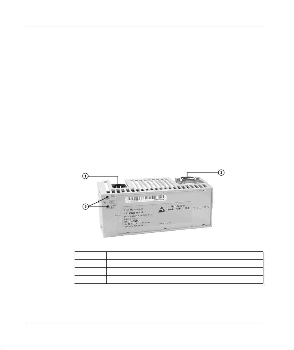
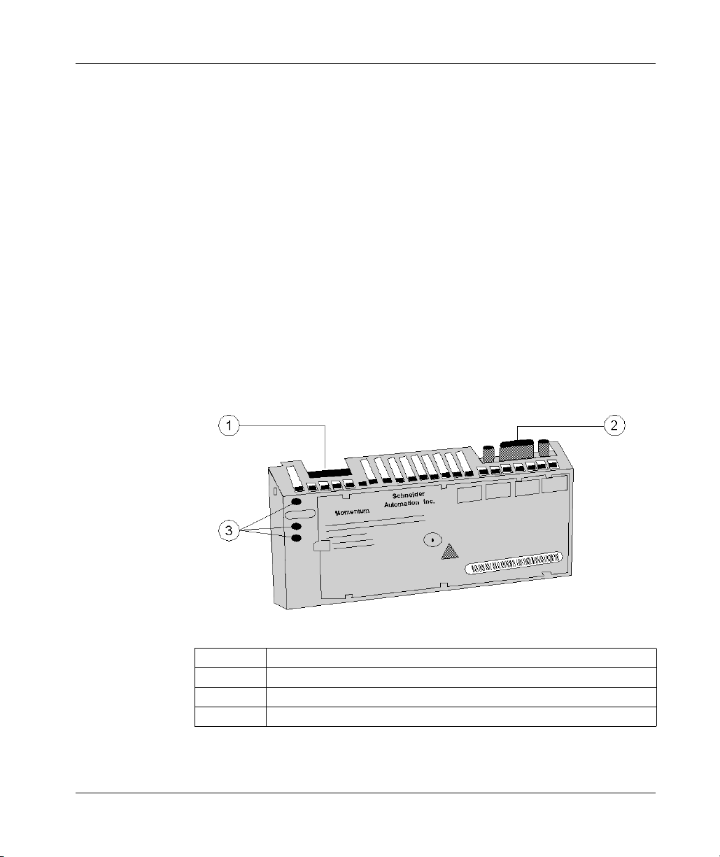
171 CCS 760 00 (M1 Processor Adapter)
Overview
This section describes the 171 CCS 760 00 processor adapter, including key
features, an illustration and specifications.
Key Features
The key features of this processor adapter are:
z Modbus port 1
z I/O bus port
z 256K bytes of internal memory
z 20 MHz clock speed
NOTE: The Modbus port connector looks like an Ethernet port connector. Do not
attempt to use a Modbus adapter as an Ethernet unit. Do not attempt to place an
Ethernet connector in a Modbus connector.
Illustration
The connector and LED indicators are shown in the following illustration:
32
Legend:
Label Description
1 Modbus Port 1 connector
2 I/0Bus port connector
3 LED indicators
31002674 4/2010

LED Indicators
Specifications
Overview of Momentum M1 Processor Adapters
This processor adapter has two LED indicators, RUN and COM ACT. Their functions
are described in the table below:
LED Status Function
Start up Both Single flash. Indicates good health.
RUN Green On continuously when the CPU has received power and is
solving logic.
Flashes an error pattern if the CPU is in kernel mode. (See Run
LED Flash Patterns and Error Codes, page 373)
Off CPU is not powered up or is not solving logic.
COM ACT Green May be on continuously or blinking. Indicates activity on
Modbus port 1.
Off No activity on Modbus port 1.
The following table contains specifications for the 171 CCS 760 00 Momentum M1
processor adapter:
Memory
Internal Memory 256K bytes
User Memory 12K words
Flash RAM 256K bytes
Clock Speed 20 MHz
Input and Output References
Registers 4096
Discretes 2048 (any combination of 0x and 1x references)
I/O Servicing
Local I/O Services all the points on any host Momentum I/O base
Watchdog Timeout 419 ms
Logic Solve Time 0.25 ms/k ladder logic instructions
Mechanical
Weight 42.5 g (1.5 oz)
Dimensions (HxDxW) 25.9x61.02x125mm
Material
(Enclosures/Bezels)
Operating Conditions
Temperature 0 ... 60 degrees C
(1.01 x 2.37 x 4.86 in)
Lexan
31002674 4/2010 33

Overview of Momentum M1 Processor Adapters
Humidity 5 ... 95% (noncondensing)
Chemical Interactions Enclosures and bezels are made of Lexan, a polycarbonate that
Altitude, Full Operation 2000m (6500ft)
Vibration 10 ... 57Hz @ 0.075mm displacement amplitude
Shock +/-15g peak, 11ms, half sine wave
RFI Susceptibility/
Immunity
Storage Conditions
Temperature -40 ... +85 degrees C
Humidity 5 ... 95% (noncondensing)
Safety Parameters
Degree of Protection Unintentional access (UL 508 Type 1, NEMA250 Type 1, IP20
Di-electric Strength RS232 and I/OBus are non-isolated from logic common
Ground Continuity 30 A test on the exposed metal connector
Agency Approvals UL 508, CSA, CUL, CE; FM class1, div2
can be damaged by strong alkaline solutions
57...150Hz @ 1g
Ref. IEC 68-2-6 FC
Ref. IEC 68-2-27 EA
Meets CE mark requirements for open equipment.
Open equipment should be installed in an industry-standard
enclosure, with access restricted to qualified service personnel.
conforming to IEC529)
34
31002674 4/2010
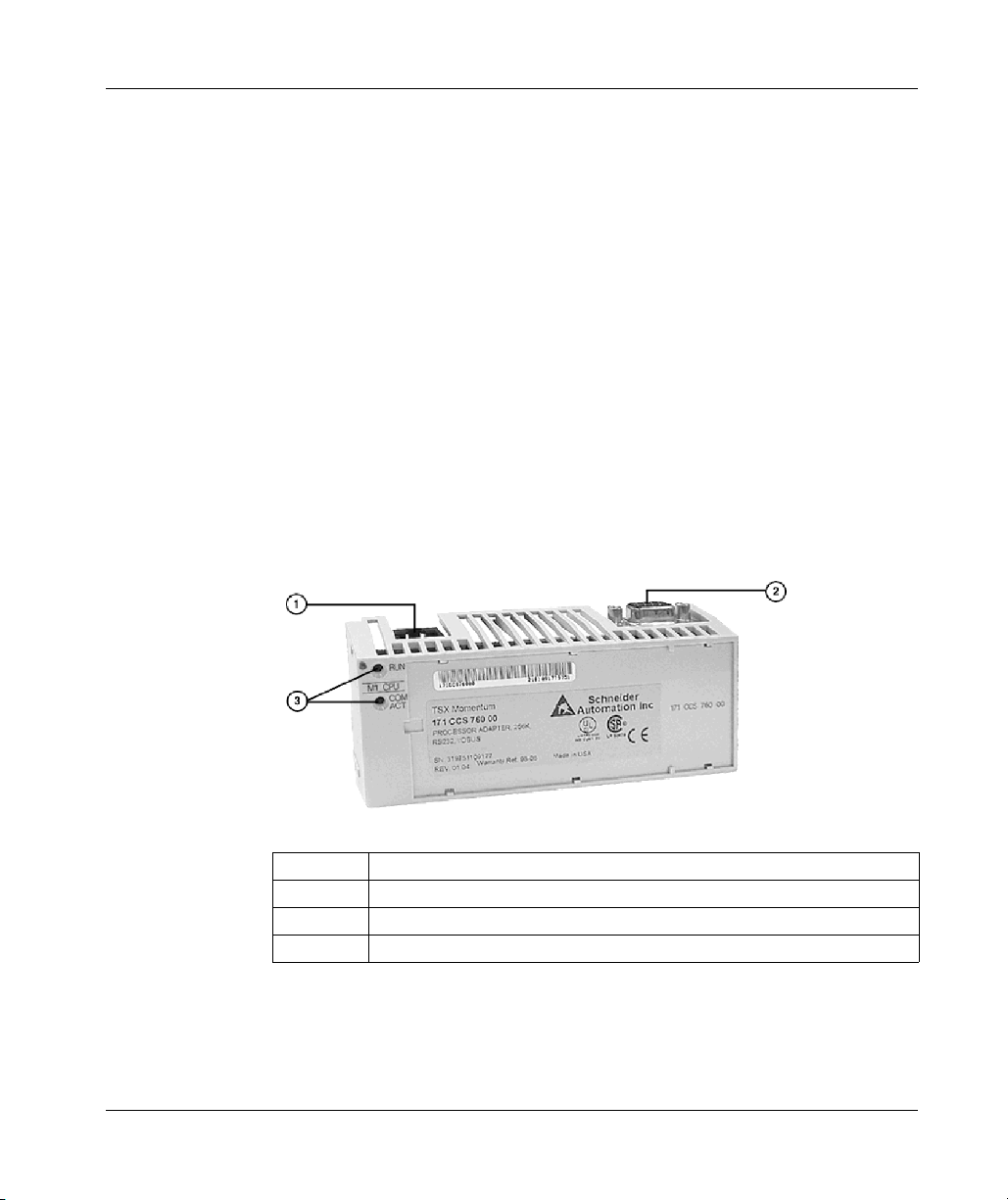
171 CCC 760 10 (M1 Processor Adapter)
Overview
This section describes the 171 CCC 760 10 processor adapter, including key
features, an illustration and specifications.
Key Features
The key features of this processor adapter are:
z Modbus port 1
z I/O bus port
z 512K bytes of internal memory
z 32 MHz clock speed
NOTE: The Modbus port connector looks like an Ethernet port connector. Do not
attempt to use a Modbus adapter as an Ethernet unit. Do not attempt to place an
Ethernet connector in a Modbus connector.
Illustration
The connector and LED indicators are shown in the following illustration:
Overview of Momentum M1 Processor Adapters
Legend:
Label Description
1 Modbus Port 1 connector
2 I/0Bus port connector
3 LED indicators
31002674 4/2010 35

Overview of Momentum M1 Processor Adapters
LED Indicators
This processor adapter has two LED indicators, RUN and COM ACT. Their functions
are described in the table below:
LED Status Function
Start up Both Single flash. Indicates good health.
RUN Green On continuously when the CPU has received power and is
Off CPU is not powered up or is not solving logic.
COM ACT Green May be on continuously or blinking. Indicates activity on
Off No activity on Modbus port 1.
Specifications
The following table contains specifications for the 171 CCC 760 10 Momentum M1
processor adapter:
Memory
Internal Memory 512K bytes
User Memory 18K words
Flash RAM 512K bytes
Clock Speed 32 MHz
Input and Output References
Registers 26032
Discretes 8192 0x references 8192 1x references
I/O Servicing
Local I/O Services all the points on any host Momentum I/O base
Watchdog Timeout 262 ms
Logic Solve Time 0.16 ms/k ladder logic instructions
Mechanical
Weight 42.5 g (1.5 oz)
Dimensions (HxDxW) 25.9x61.02x125mm
Material
(Enclosures/Bezels)
Operating Conditions
Temperature 0 ... 60 degrees C
solving logic.
Flashes an error pattern if the CPU is in kernel mode. (See Run
LED Flash Patterns and Error Codes, page 373)
Modbus port 1.
(1.01 x 2.37 x 4.86 in)
Lexan
36
31002674 4/2010

Overview of Momentum M1 Processor Adapters
Humidity 5 ... 95% (noncondensing)
Chemical Interactions Enclosures and bezels are made of Lexan, a polycarbonate that
can be damaged by strong alkaline solutions
Altitude, Full Operation 2000m (6500ft)
Vibration 10 ... 57Hz @ 0.075mm displacement amplitude
57...150Hz @ 1g
Ref. IEC 68-2-6 FC
Shock +/-15g peak, 11ms, half sine wave
Ref. IEC 68-2-27 EA
RFI Susceptibility/
Immunity
Meets CE mark requirements for open equipment.
Open equipment should be installed in an industry-standard
enclosure, with access restricted to qualified service personnel.
Storage Conditions
Temperature -40 ... +85 degrees C
Humidity 5 ... 95% (noncondensing)
Safety Parameters
Degree of Protection Unintentional access (UL 508 Type 1, NEMA250 Type 1, IP20
conforming to IEC529)
Di-electric Strength RS232 and I/OBus are non-isolated from logic common
Ground Continuity 30 A test on the exposed metal connector
Agency Approvals UL 508, CSA, CUL, CE; FM class1, div2
31002674 4/2010 37

Overview of Momentum M1 Processor Adapters
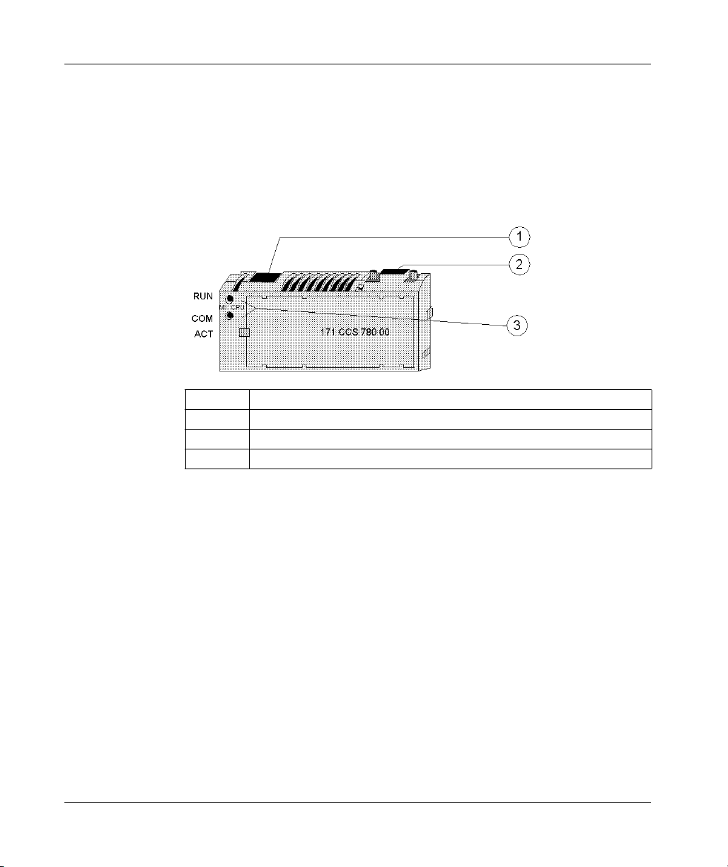
171 CCS 780 00 (M1 Processor Adapter)
Overview
This section describes the 171 CCS 780 00 processor adapter, including key
features, an illustration and specifications.
Key Features
The key features of this processor adapter are:
z Modbus port 1
z Modbus port 2
z 64K bytes of internal memory
z 20 MHz clock speed
NOTE: The Modbus port connector looks like an Ethernet port connector. Do not
attempt to use a Modbus adapter as an Ethernet unit. Do not attempt to place an
Ethernet connector in a Modbus connector.
Illustration
The connector and LED indicators are shown in the following illustration:
38
Legend:
Label Description
1 Modbus Port 1 connector
2 Modbus Port 2 connector
3 LED indicators
31002674 4/2010

LED Indicators
Specifications
Overview of Momentum M1 Processor Adapters
This processor adapter has two LED indicators, RUN and COM ACT. Their functions
are described in the table below:
LED Status Function
Start up Both Single flash. Indicates good health.
RUN Green On continuously when the CPU has received power and is
solving logic.
Flashes an error pattern if the CPU is in kernel mode. (See Run
LED Flash Patterns and Error Codes, page 373)
Off CPU is not powered up or is not solving logic.
COM ACT Green May be on continuously or blinking. Indicates activity on
Modbus port 1.
Off No activity on Modbus port 1.
The following table contains specifications for the 171 CCS 780 00 Momentum M1
processor adapter:
Memory
Internal Memory 64K bytes
User Memory 2.4K words
Flash RAM 256K bytes
Clock Speed 20 MHz
Input and Output References
Registers 2048
Discretes 2048 (any combination of 0x and 1x references)
I/O Servicing
Local I/O Services all the points on any host Momentum I/O base
Watchdog Timeout 419 ms
Logic Solve Time 0.25 ms/k ladder logic instructions
Mechanical
Weight 42.5 g (1.5 oz)
Dimensions (HxDxW) 25.9x61.02x125mm
Material
(Enclosures/Bezels)
Operating Conditions
Temperature 0 ... 60 degrees C
(1.01 x 2.37 x 4.86 in)
Lexan
31002674 4/2010 39

Overview of Momentum M1 Processor Adapters
Humidity 5 ... 95% (noncondensing)
Chemical Interactions Enclosures and bezels are made of Lexan, a polycarbonate that
Altitude, Full Operation 2000m (6500ft)
Vibration 10 ... 57Hz @ 0.075mm displacement amplitude
Shock +/-15g peak, 11ms, half sine wave
RFI Susceptibility/
Immunity
Storage Conditions
Temperature -40 ... +85 degrees C
Humidity 5 ... 95% (noncondensing)
Safety Parameters
Degree of Protection Unintentional access (UL 508 Type 1, NEMA250 Type 1, IP20
Di-electric Strength RS232 and I/OBus are non-isolated from logic common
Ground Continuity 30 A test on the exposed metal connector
Agency Approvals UL 508, CSA, CUL, CE; FM class1, div2
can be damaged by strong alkaline solutions
57...150Hz @ 1g
Ref. IEC 68-2-6 FC
Ref. IEC 68-2-27 EA
Meets CE mark requirements for open equipment.
Open equipment should be installed in an industry-standard
enclosure, with access restricted to qualified service personnel.
conforming to IEC529)
40
31002674 4/2010
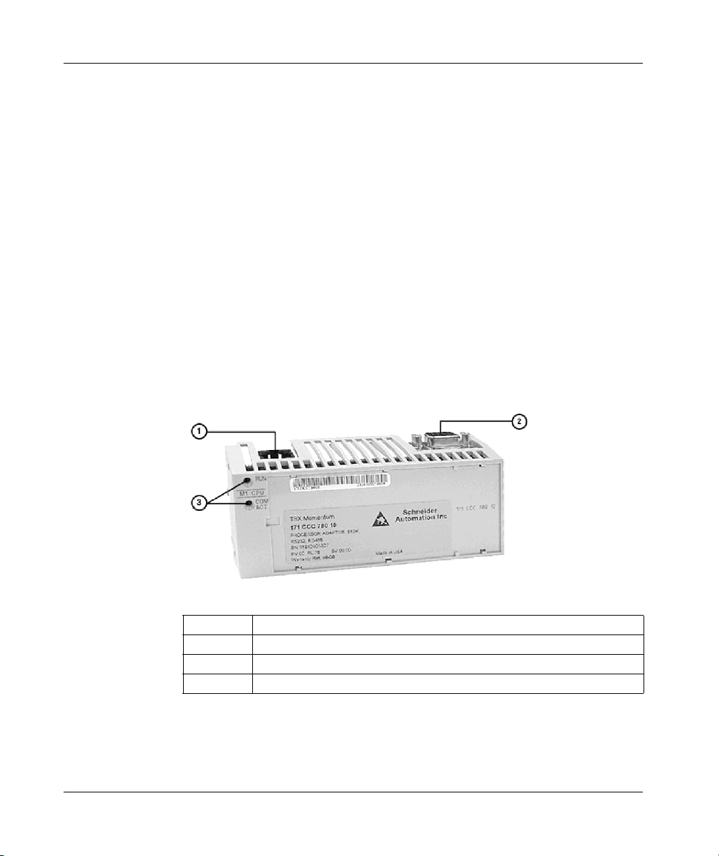
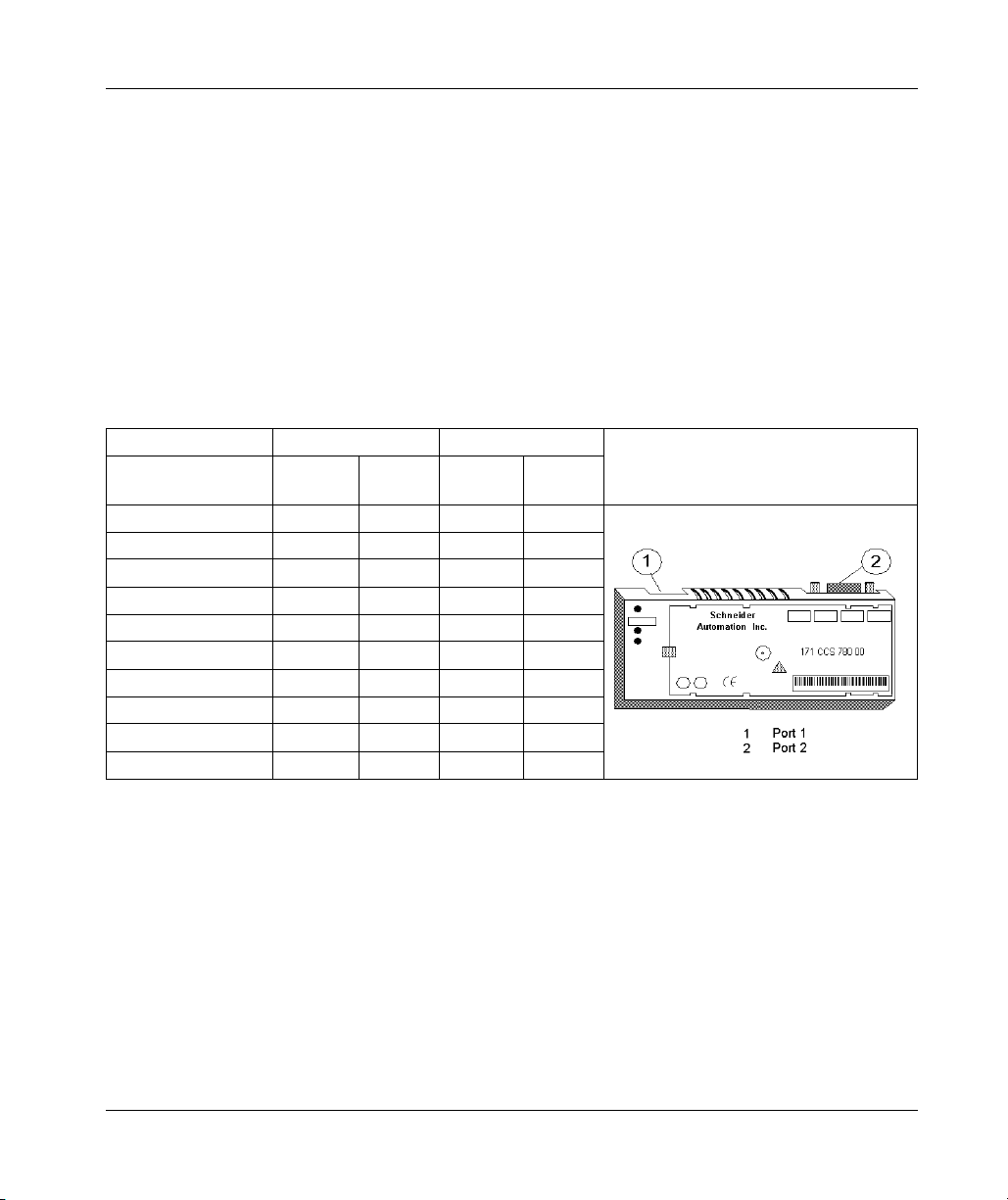
171 CCC 780 10 (M1 Processor Adapter)
Overview
This section describes the 171 CCC 780 10 processor adapter, including key
features, an illustration and specifications.
Key Features
The key features of this processor adapter are:
z Modbus port 1
z Modbus port 2
z 512K bytes of internal memory
z 32 MHz clock speed
NOTE: The Modbus port connector looks like an Ethernet port connector. Do not
attempt to use a Modbus adapter as an Ethernet unit. Do not attempt to place an
Ethernet connector in a Modbus connector.
Illustration
The connector and LED indicators are shown in the following illustration:
Overview of Momentum M1 Processor Adapters
Legend:
Label Description
1 Modbus Port 1 connector
2 Modbus Port 2 connector
3 LED indicators
31002674 4/2010 41

Overview of Momentum M1 Processor Adapters
LED Indicators
This processor adapter has two LED indicators, RUN and COM ACT. Their
functions are described in the table below:
LED Status Function
Start up Both Single flash. Indicates good health.
RUN Green On continuously when the CPU has received power and is
Off CPU is not powered up or is not solving logic.
COM ACT Green May be on continuously or blinking. Indicates activity on
Off No activity on Modbus port 1.
Specifications
The following table contains specifications for the 171 CCC 780 10 Momentum M1
processor adapter:
Memory
Internal Memory 512K bytes
User Memory 18K words
Flash RAM 512K bytes
Clock Speed 32 MHz
Input and Output References
Registers 26032
Discretes 8192 0x references
I/O Servicing
Local I/O Services all the points on any host Momentum I/O base
Watchdog Timeout 262 ms
Logic Solve Time 0.16 ms/k ladder logic instructions
Mechanical
Weight 42.5 g (1.5 oz)
Dimensions (HxDxW) 25.9x61.02x125mm
Material
(Enclosures/Bezels)
Operating Conditions
solving logic.
Flashes an error pattern if the CPU is in kernel mode . (See Run
LED Flash Patterns and Error Codes, page 373)
Modbus port 1.
8192 1x references
(1.01 x 2.37 x 4.86 in)
Lexan
42
31002674 4/2010

Overview of Momentum M1 Processor Adapters
Temperature 0 ... 60 degrees C
Humidity 5 ... 95% (noncondensing)
Chemical Interactions Enclosures and bezels are made of Lexan, a polycarbonate that
can be damaged by strong alkaline solutions
Altitude, Full Operation 2000m (6500ft)
Vibration 10 ... 57Hz @ 0.075mm displacement amplitude
57...150Hz @ 1g
Ref. IEC 68-2-6 FC
Shock +/-15g peak, 11ms, half sine wave
Ref. IEC 68-2-27 EA
RFI Susceptibility/
Immunity
Meets CE mark requirements for open equipment.
Open equipment should be installed in an industry-standard
enclosure, with access restricted to qualified service personnel.
Storage Conditions
Temperature -40 ... +85 degrees C
Humidity 5 ... 95% (noncondensing)
Safety Parameters
Degree of Protection Unintentional access (UL 508 Type 1, NEMA250 Type 1, IP20
conforming to IEC529)
Di-electric Strength RS232 and I/OBus are non-isolated from logic common
Ground Continuity 30 A test on the exposed metal connector
Agency Approvals UL 508, CSA, CUL, CE; FM class1, div2
31002674 4/2010 43

Overview of Momentum M1 Processor Adapters
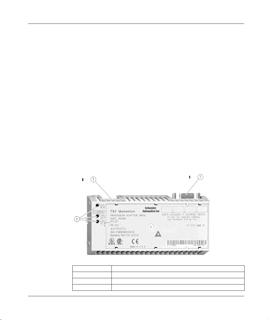
171 CCC 960 20 (M1 Processor Adapter)
Overview
This section describes the 171 CCC 960 20 processor adapter, including key
features, an illustration, and specifications.
Key Features
The key features of this processor adapter are
z Ethernet port
z I/O bus port
z 544K bytes of internal memory
z 50 MHz clock speed
NOTE: The Ethernet port connector looks like a Modbus port connector. Do not
attempt to use an Ethernet adapter as a Modbus unit. Do not attempt to place a
Modbus connector in an Ethernet connector.
Illustration
The connectors and LED indicators are shown in the following illustration:
44
Legend:
Label Description
1 Ethernet port connector
2 I/OBus port connector
3 LED indicators
31002674 4/2010

LED Indicators
Overview of Momentum M1 Processor Adapters
This processor adapter has three LED indicators, RUN LAN ACT(IVE), and LAN
ST(ATUS). Their functions are described in the table below:
Specifications
LED Indicator
Pattern
Start up Both Single flash. Indicates good health.
RUN Green On continuously when the CPU has received power and is
Off CPU is not powered up or is not solving logic.
LAN ACT Green May be on continuously or blinking. Indicates activity on
Off No activity on Ethernet port.
LAN ST Green On continuously during normal operation.
Off No valid MAC address.
Status
solving logic.
Flashes an error pattern if the CPU is in kernel mode. (See Run
LED Flash patterns and error codes.)
Ethernet port.
Fast blink indicates normal Ethernet initialization at power-up.
3 flashes indicates no 10BASE-T link pulse detected. Check
cable and hub.
4 flashes indicates duplicate IP address detected.
5 flashes indicates no IP address available.
The following table contains specifications for the 171 CCC 960 20 Momentum M1
processor adapter.
Memory
Internal Memory 544K bytes
User Memory 18K words
Flash RAM 512K bytes
Clock Speed 50 MHz
Input and Output References
Registers 26048
Discretes 8192 0x references
I/O Servicing
Local I/O Services all the points on any host Momentum I/O base
Watchdog Timeout 335 ms
31002674 4/2010 45
8192 1x references

Overview of Momentum M1 Processor Adapters
Logic Solve Time See Scantime Formula for 984LL Exec, following
Mechanical
Weight 42.5 g (1.5 oz)
Dimensions (HxDxW) 25.9x61.02x125mm
Material
(Enclosures/Bezels)
Operating Conditions
Temperature 0 ... 60 degrees C
Humidity 5 ... 95% (noncondensing)
Chemical Interactions Enclosures and bezels are made of Lexan, a polycarbonate that
Altitude, Full Operation 2000m (6500ft)
Vibration 10 ... 57Hz @ 0.075mm displacement amplitude
Shock +/-15g peak, 11ms, half sine wave
RFI Susceptibility/
Immunity
Storage Conditions
Temperature -40 ... +85 degrees C
Humidity 5 ... 95% (noncondensing)
Safety Parameters
Degree of Protection Unintentional access (UL 508 Type 1, NEMA250 Type 1, IP20
Di-electric Strength Ethernet is isolated from logic common 500 VDC.
Ground Continuity 30 A test on the exposed metal connector
Agency Approvals UL 508, CSA, CUL, CE; FM class1, div2
(1.01 x 2.37 x 4.86 in)
Lexan
can be damaged by strong alkaline solutions
57...150Hz @ 1g
Ref. IEC 68-2-6 FC
Ref. IEC 68-2-27 EA
Meets CE mark requirements for open equipment.
Open equipment should be installed in an industry-standard
enclosure, with access restricted to qualified service personnel.
conforming to IEC529)
46
31002674 4/2010

Scantime Formula for 984LL Exec
The following formula applies to the M1E processor adapter with the 984LL exec.
Scan time = (0.25 msec/ethernet device + 0.002 msec/word) + 0.13 msec/K of logic
+ 0.40 msec + MBPlustime
NOTE:
z Modbus Plus communications will slow the M1E. If there is no MB+ ring card,
then MBPlustime = 0.
z If there is a MB+ ring card, then each scan will be extended 0.3 Msec even if there
is no message.
z Modbus Messages will add from 1 to 2 msec per scan, depending on the length
of the message.
NOTE:
z The formula above presumes that all MSTR blocks and all configured
connections are set to go as fast as possible. In this case the M1E will attempt to
exchange data with each device once per scan.
z If several devices are configured to communicate on a timed basis that is
substantially larger than the scan time calculated, then the communications to
those devices will be spread out over several scans. See Example, below.
Example
You have 50 ENT modules connected to a single M1E. The M1E has a configured
time of 50 Msec each, a total of 4k user logic, and no MB+ card. The scan time for
all modules configured as fast as possible would be 12.5 Msec + 0.52 Msec + 0.40
Msec = 13.42 Msec. However, since the M1E will only communicate to 1/4 of the
modules (12.5 Msec/50 Msec = 1/4) on any given scan, the corrected average scan
time would be 1/4 x (12.5) + 0.52 + 0.40 @ 4.1 Msec.
Overview of Momentum M1 Processor Adapters
31002674 4/2010 47
Overview of Momentum M1 Processor Adapters
171 CCC 960 30 M1 Processor Adapter
Overview
This section describes the 171 CCC 960 30 processor adapter, including key
features, an illustration, and specifications.
NOTE: The 171CCC 960 30 units are shipped with the latest IEC exec installed.
NOTE: The 984LL exec used in the 171 CCC 960 30 will not operate in a171 CCC
960 20.
Key Features
The key features of this processor adapter are
z Ethernet port
z I/O bus port
z 544K bytes of internal memory
z 50 MHz clock speed
NOTE: The Ethernet port connector looks like a Modbus port connector. Do not
attempt to use an Ethernet adapter as a Modbus unit. Do not attempt to place a
Modbus connector in an Ethernet connector.
Illustration
The connectors and LED indicators are shown in the following illustration.
48
Legend:
Label Description
1 Ethernet port connector
2 I/OBus port connector
3 LED indicators
31002674 4/2010

LED Indicators
Overview of Momentum M1 Processor Adapters
This processor adapter has three LED indicators, RUN, LAN ACT(IVE), and LAN
ST(ATUS). Their functions are described in the table below.
Specifications
LED Indicator
Pattern
Start up Both Single flash. Indicates good health.
Run Green On continuously when the CPU has received power and is solving
Off CPU is not powered up or is not solving logic.
LAN ACT Green May be on continuously or blinking. Indicates activity on Ethernet
Off No activity on Ethernet port.
LAN ST Green On continuously during normal operation.
Off No valid MAC address.
Status
logic.
Flashes an error pattern if the CPU is in kernel mode. (See Run LED
Flash Patterns and Error Codes.
port.
Fast blink indicates normal Ethernet initialization at power-up.
3 Flashes indicates no 10BASE-T link pulse detected. Check cable
and hub.
4 flashes indicates duplicate IP address detected.
5 flashes indicates no IP address available.
The following table contains specifications for the 171 CCC 960 30 Momentum M1
processor adapter.
Memory
Internal Memory 544K bytes
User Memory 18K words 984LL Exec
200k words IEC Exec
Flash RAM 1 Megabyte
Clock Speed 50 MHz
984LL Input and Output References
Registers 26048
Discretes 8192 0x References
IEC Input and Output References
Registers 11200
31002674 4/2010 49
8192 1x References

Overview of Momentum M1 Processor Adapters
Discretes 4096 0x References
I/O Servicing
Local I/O Services all the points on any host Momentum I/O base
Watchdog Timeout 335 ms
Logic Solve Time See Scantime Formula for 984LL Exec, following
Mechanical
Weight 42.5 g (1.5 oz.)
Dimensions (HxDxW 25.9x61.02x125mm
Material
(Enclosures/Bezels)
Operating Conditions
Temperature 0 ... 60 degrees C
Humidity 5 ... 95% (noncondensing)
Chemical Interactions Enclosures and bezels are made of Lexan, a polycarbonate that
Altitude, Full Operation 2000m (6500ft.)
Vibration 10 ... 57Hz @ 0.075mm displacement amplitude
Shock +/-15g peak, 11ms, half sine wave
RFI
Susceptibility/Immunity
Storage Conditions
Temperature -40 ... +85 degrees C
Humidity 5 ... 95% (noncondensing)
Safety Parameters
Degree of Protection Unintentional access (UL 508 Type 1, NEMA250 Type 1, IP20
Di-electric Strength Ethernet is isolated from logic common 500 VDC
Ground Continuity 30 A test on the exposed metal connector
Agency approvals UL 508, CSA, CUL, CE; FM class1, div2 pending
4096 1x References
(1.01 x 2.37 x 4.86 in.)
Lexan
can be damaged by strong alkaline solutions
57 ... 150Hz @ 1g
Ref. IEC 68-2-6 FC
Ref. IEC 68-2-27 EA
Meets CE mark requirements for open equipment. Open
equipment should be installed in an industry-standard enclosure,
with access restricted to qualified service personnel.
conforming to IEC529)
50
31002674 4/2010

Scantime Formula for 984LL Exec
The following formula applies to the M1E processor adapter with the 984LL exec.
Scan time = (0.25 msec/ethernet device + 0.002 msec/word) + 0.13 msec/K of logic
+ 0.40 msec + MBPlustime.
NOTE:
z Modbus Plus communications will slow the M1E. If there is no MB+ ring card,
then MBPlustime = 0.
z If there is a MB+ ring card, then each scan will be extended 0.3 Msec even if there
is no message.
z Modbus Messages will add from 1 to 2 msec per scan, depending on the length
of the message.
NOTE:
z The formula above presumes that all MSTR blocks and all configured
connections are set to go as fast as possible. In this case the M1E will attempt to
exchange data with each device once per scan.
z If several devices are configured to communicate on a timed basis that is
substantially larger than the scan time calculated, then the communications to
those devices will be spread out over several scans. See Example, below.
Example
You have 50 ENT modules connected to a single M1E. The M1E has a configured
time of 50 Msec each, a total of 4k user logic and no MB+ card. The scan time for
all modules configured as fast as possible would be 12.5 Msec + 0.52 Msec + 0.40
Msec = 13.42 Msec. However, since the M1E will only communicate to 1/4 of the
modules (12.5 Msec/50 Msec = 1/4) on any given scan, the corrected average scan
time would be 1/4 x (12.5) + 0.52 + 0.40 @ 4.1 Msec.
Overview of Momentum M1 Processor Adapters
31002674 4/2010 51
Overview of Momentum M1 Processor Adapters
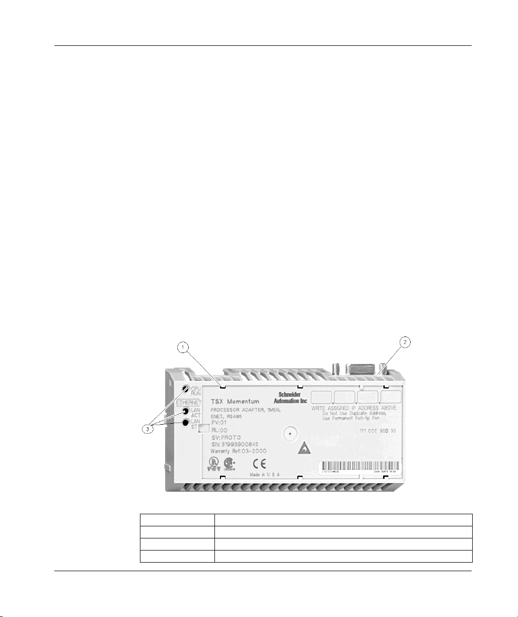
171 CCC 980 20 (M1 Processor Adapter)
Overview
This section describes the 171 CCC 980 20 processor adapter, including key
features, an illustration, and specifications.
Key Features
The key features of this processor adapter are
z Ethernet port
z Modbus Port 2/RS485 only
z 544K bytes of internal memory
z 50 MHz clock speed
NOTE: The Ethernet port connector looks like a Modbus port connector. Do not
attempt to use an Ethernet adapter as a Modbus unit. Do not attempt to place a
Modbus connector in an Ethernet connector.
Illustration
The connector and LED indicators are shown in the following illustration:
52
Legend:
Label Description
1 Ethernet port connector
2 Modbus Port 2 connector
3 LED indicators
31002674 4/2010

LED Indicators
Overview of Momentum M1 Processor Adapters
This processor adapter has three LED indicators, RUN LAN ACT(IVE), and LAN
ST(ATUS). Their functions are described in the table below.
Specifications
LED Indicator
Pattern
Start up Both Single flash. Indicates good health.
RUN Green On continuously when the CPU has received power and is
Off CPU is not powered up or is not solving logic.
LAN ACT Green May be on continuously or blinking. Indicates activity on
Off No activity on Ethernet port.
LAN ST Green On continuously during normal operation.
Off No valid MAC address.
Status
solving logic.
Flashes an error pattern if the CPU is in kernel mode. (See Run
LED Flash Patterns and Error Codes.)
Ethernet port.
Fast blink indicates normal Ethernet initialization at power-up.
3 flashes indicates no 10BASE-T link pulse detected. Check
cable and hub.
4 flashes indicates duplicate IP address detected.
5 flashes indicates no IP address available.
The following table contains specifications for the 171 CCC 980 20 Momentum M1
processor adapter.
Memory
Internal Memory 544K bytes
User Memory 18K words
Flash RAM 512K bytes
Clock Speed 50 MHz
Input and Output References
Registers 26048
Discretes 8192 0x references; 8192 1x references
I/O Servicing
Local I/O Services all the points on any host Momentum I/O base
Watchdog Timeout 335 ms
Logic Solve Time See Scantime Formula for 984LL Exec, following
31002674 4/2010 53

Overview of Momentum M1 Processor Adapters
Mechanical
Weight 42.5 g (1.5 oz.)
Dimensions (HxDxW) 25.9x61.02x125mm
Material
(Enclosures/Bezels)
Operating Conditions
Temperature 0 ... 60 degrees C
Humidity 5 ... 95% (noncondensing)
Chemical Interactions Enclosures and bezels are made of Lexan, a polycarbonate that
Altitude, Full Operation 2000m (6500ft)
Vibration 10 ... 57Hz @ 0.075mm displacement amplitude
Shock +/-15g peak, 11ms, half sine wave
RFI Susceptibility/
Immunity
Storage Conditions
Temperature -40 ... +85 degrees C
Humidity 5 ... 95% (noncondensing)
Safety Parameters
Degree of Protection Unintentional access (UL 508 Type 1, NEMA250 Type 1, IP20
Di-electric Strength Ethernet is isolated from logic common 500 VDC
Ground Continuity 30 A test on the exposed metal connector
Agency Approvals UL 508, CSA, CUL, CE; FM class1, div2
(1.01 x 2.37 x 4.86 in)
Lexan
can be damaged by strong alkaline solutions
57...150Hz @ 1g
Ref. IEC 68-2-6 FC
Ref. IEC 68-2-27 EA
Meets CE mark requirements for open equipment.
Open equipment should be installed in an industry-standard
enclosure, with access restricted to qualified service personnel.
conforming to IEC529)
54
31002674 4/2010

Scantime Formula for 984LL Exec
The following formula applies to the M1E processor adapter with the 984LL exec.
Scan time = (0.25 msec/ethernet device + 0.002 msec/word) + 0.13 msec/K of logic
+ 0.40 msec + MBPlustime
NOTE:
z Modbus Plus communications will slow the M1E. If there is no MB+ ring card,
then MBPlustime = 0.
z If there is a MB+ ring card, then each scan will be extended 0.3 Msec even if there
is no message.
z Modbus Messages will add from 1 to 2 msec per scan, depending on the length
of the message.
NOTE:
z The formula above presumes that all MSTR blocks and all configured
connections are set to go as fast as possible. In this case the M1E will attempt to
exchange data with each device once per scan.
z If several devices are configured to communicate on a timed basis that is
substantially larger than the scan time calculated, then the communications to
those devices will be spread out over several scans. See Example, below.
Example
You have 50 ENT modules connected to a single M1E. The M1E has a configured
time of 50 Msec each, a total of 4k user logic, and no MB+ card. The scan time for
all modules configured as fast as possible would be 12.5 Msec + 0.52 Msec + 0.40
Msec = 13.42 Msec. However, since the M1E will only communicate to 1/4 of the
modules (12.5 Msec/50 Msec = 1/4) on any given scan, the corrected average scan
time would be 1/4 x (12.5) + 0.52 + 0.40 @ 4.1 Msec
Overview of Momentum M1 Processor Adapters
31002674 4/2010 55
Overview of Momentum M1 Processor Adapters
171 CCC 980 30 (M1 Processor Adapter)
Overview
This section describes the 171 CCC 980 30 processor adapter, including key
features, an illustration, and specifications.
NOTE: The 171 CCC 980 30 units are shipped with the latest IEC exec installed.
NOTE: The 984LL exec used in the 171 CCC 980 30 will not operate in a 171 CCC
980 20
Key Features
The key features of this processor Adapter are
z Ethernet port
z Modbus port 2 / RS485 only
z 544K bytes of internal memory
z 50 MHz clock speed
NOTE: The Ethernet port connector looks like a Modbus port connector. Do not
attempt to use an Ethernet adapter as a Modbus unit. Do not attempt to place a
Modbus connector in an Ethernet connector.
Illustration
The connectors and LED indicators are shown in the following illustration.
56
Legend:
Label Description
1 Ethernet port connector
2 Modbus Port 2 connector
3 LED indicators
31002674 4/2010

LED Indicators
Overview of Momentum M1 Processor Adapters
This processor adapter has three LED indicators, RUN, LAN ACT(IVE), and LAN
ST(ATUS). Their functions are described in the table below.
Specifications
LED Indicator
Pattern
Start up Both Single flash. Indicates good health.
RUN Green On continuously when the CPU and is solving logic.
Off CPU is not powered up or is not solving logic.
LAN ACT Green Maybe on continuously or blinking. Indicates activity on Ethernet
Off No activity on Ethernet port.
LAN ST Green On continuously during normal operation.
Off No valid MAC address.
Status
Flashes an error pattern if the CPU is in kernel mode. (See Run
LED Flash Patterns and Error Codes.)
port.
Fast blink indicates normal Ethernet initialization at power-up.
3 flashes indicates no 10Base-T link pulse detected. Check
cable and hub.
4 flashes indicates duplicate IP address detected.
5 flashes indicates no IP address available.
The following table contains specifications for the 171 CCC 980 30 Momentum M1
processor adapter.
Memory
Internal Memory 544K bytes
User Memory 18K words 984LL Exec
200k words IEC Exec
Flash RAM 1 Megabyte
Clock Speed 50 MHz
984LL Input and Output References
Registers 26048
Discretes 8192 0x references
8192 1x references
IEC Input and Output References
Registers 11200
31002674 4/2010 57

Overview of Momentum M1 Processor Adapters
Discretes 4096 0x references
I/O Servicing
Local I/O Services all the points on any host Momentum I/O base
Watchdog Timeout 335 ms
Logic Solve Time See Scantime Formula for 984LL Exec, following
Mechanical
Weight 42.5 g (1.5 oz.)
Dimensions (HxDxW) 25.9 x 61.02 x 125mm
Material
(Enclosures/Bezels)
Operating Conditions
Temperature 0 ... 60 degrees C
Humidity 5 ... 95% (noncondensing)
Chemical Interactions Enclosures and bezels are made of Lexan, a polycarbonate that
Altitude, Full Operation 2000m (6500ft.)
Vibration 10 ... 57Hz @ 0.075mm displacement amplitude
Shock +/-15g peak, 11ms, half sine wave
RFI
Susceptibility/Immunity
Storage Conditions
Temperature -40 ... +85 degrees C
Humidity 5 ... 95% (noncondensing)
Safety Parameters
Degree of Protection Unintentional access (UL 508 Type 1, NEMA250 Type 1, IP20
Di-electric Strength Ethernet is isolated from logic common 500 VDC
Ground Continuity 30 A test on the exposed metal connector
Agency Approvals UL 508, CSA, CUL, CE; FM class 1, div2
4096 1x references
(1.01 x 2.37 x 4.86 in.)
Lexan
can be damaged by strong alkaline solutions.
57 ... 150Hz @ 1g
Ref. IEC 68-2-6 FC
Ref. IEC 68-2-27 EA
Meets CE mark requirements for open equipment.
Open equipment should be installed in an industry-standard
enclosure, with access restricted to qualified service personnel.
conforming to IEC529)
58
31002674 4/2010

Scantime Formula for 984LL Exec
The following formula applies to the M1E processor adapter with the 984LL exec.
Scan time = (0.25 msec/ethernet device + 0.002 msec/word) + 0.13 msec/K of logic
+ 0.40 msec + MBPlustime
NOTE: The following are important.
z Modbus Plus communications will slow the M1E. If there is no MB+ ring card,
then MBPlustime = 0.
z If there is a MB+ ring card, then each scan will be extended 0.3 Msec even if there
is no message.
z Modbus Messages will add from 1 to 2 msec per scan, depending on the length
of the message.
NOTE: The following are important.
z The formula above presumes that all MSTR blocks and all configured
connections are set to go as fast as possible. In this case the M1E will attempt to
exchange data with each device once per scan.
z If several devices are configured to communicate on a timed basis that is
substantially larger than the scan time calculated, then the communications to
those devices will be spread out over several scans. See Example, below.
Example
You have 50 ENT modules connected to a single M1E. The M1E has a configured
time of 50 Msec each, a total of 4k user logic, and no MB+ card. The scan time for
all modules configured as fast as possible would be 12.5 Msec + 0.52 Msec + 0.40
Msec = 13.42 Msec. However, since the M1E will only communicate to 1/4 of the
modules (12.5 Msec/50 Msec = 1/4) on any given scan, the corrected average scan
time would be 1/4 x (12.5) + 0.52 + 0.40 @ 4.1 Msec.
Overview of Momentum M1 Processor Adapters
31002674 4/2010 59

Overview of Momentum M1 Processor Adapters
60
31002674 4/2010

Overview of Momentum Option Adapters
31002674 4/2010
Overview of Momentum
Option Adapters
Purpose
An option adapter may be inserted between the processor adapter and the I/O base
to provide:
z A battery backup for the CPU
z A time-of-day clock
z Extra communication ports
This chapter describes the three types of Momentum option adapters.
What's in this Chapter?
This chapter contains the following sections:
2.1 Introducing the Momentum Option Adapters 62
2.2 Serial Option Adapter (Momentum) 63
2.3 Modbus Plus Option Adapter 67
2.4 Redundant Modbus Plus Option Adapter (A Momentum
2
Section Topic Page
71
Component)
31002674 4/2010 61

Overview of Momentum Option Adapters
2.1 Introducing the Momentum Option Adapters
Basic Features of Option Adapters
Introduction
This section describes the basic features common to all option adapters.
z the battery
z a time-of-day (TOD) clock
z the communication port(s)
Battery
The battery backs up the CPU’s user program and state RAM.
TOD Clock
The TOD clock allows you to use the date and time as an element in your user
program.
Communication Ports
The three Momentum option adapters are distinguished by the communications
ports they offer, as shown in the table below.
62
Option Adapter Communication Port(s)
172 JNN 210 32 Software-selectable RS232/RS485 serial port
172 PNN 210 22 One Modbus Plus port
172 PNN 260 22 Two Modbus Plus ports for a redundant (back-up) cable run
31002674 4/2010

Overview of Momentum Option Adapters
2.2 Serial Option Adapter (Momentum)
Purpose
This section describes the 172 JNN 210 32 serial option adapter, including the front
panel components and specifications.
What's in this Section?
This section contains the following topics:
Topic Page
Front Panel Components of Momentum Serial Option Adapter 64
Specifications of the Momentum Serial Option Adapter 66
31002674 4/2010 63
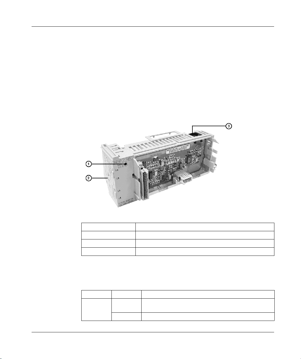
Overview of Momentum Option Adapters
Front Panel Components of Momentum Serial Option Adapter
Overview
The front panel includes:
z An LED indicator
z Battery compartment
z Modbus port 2 connector
Illustration
The illustration below shows the location of LED indicator, the battery compartment,
and the Modbus port 2 connector.
LED Indicator
64
Legend:
Label Description
1 LED indicator
2 Battery compartment door
3 Modbus Port 2 connector
This option adapter has one LED indicator, the Com Act indicator. Its functions are
described in the table below
LED Status Function
COM ACT Green May be on steadily or blinking. Indicates activity on the
RS232/RS485 serial port.
Off No activity on the RS232/RS485 serial port.
31002674 4/2010

Modbus Port 2
Modbus port 2 is a general-purpose asynchronous serial port with user-selectable
RS232/RS485 slave functionality. The choice between RS232 and RS485 is made
in the software.
NOTE: When this option adapter is assembled with a 171 CCS 780 00 processor
adapter or a 171 CCC 780 10 processor adapter (with built-in Modbus port 2), the
Modbus port 2 on the option adapter is electrically disabled. The TOD clock and the
battery backup on the option adapter remain functional.
Auto-Logout Feature On Modbus Port 2
If the RS232 port is chosen, auto-logout is supported. If a programming panel is
logged into the CPU via the serial port and its cable gets disconnected, the
processor adapter automatically logs out the port. This auto-logout feature is
designed to prevent a lock-up situation that could prevent other host stations from
logging in on other ports.
Auto-logout is not available for any RS485 port, including the RS485 option on the
serial option adapter. The user must log out of the processor using the programming
software.
Pinouts for Modbus Port 2
The 172 JNN 210 32 serial option adapter uses the following pinouts:
Overview of Momentum Option Adapters
Pin For RS232 For RS485
1DTR RXD -
2DSR RXD +
3TXD TXD +
4RXD
5 signal common signal common
6 RTS TXD -
7CTS
8 cable shield cable shield
31002674 4/2010 65

Overview of Momentum Option Adapters
Specifications of the Momentum Serial Option Adapter
172 JNN 210 32 Serial Option Adapter Specifications
Mechanical
Weight 85.05 g (3 oz.)
Dimensions (HxDxW) 58.3 (on battery side) x 60.6 x 143.1 mm
(2.27 x 2.36 x 5.57 in)
Material (enclosures/bezels) Lexan
Time-of-Day Clock
Accuracy +/- 13 s/day
Battery one 2/3 AA lithium required; included in a separate package
with the option adapter
Service Life < 30 days from the time a battery-low indication is received
to actual battery failure @ 40 degrees C maximum ambient
temperature with the system continuously powered down.
Shelf Life In excess of 5 yr. @ room temperature
Operating Conditions
Temperature 0 ... 60 degrees C
Humidity 5 ... 95% (noncondensing)
Chemical Interactions Enclosures and bezels are made of Lexan, a polycarbonate
that can be damaged by strong alkaline solutions
Altitude, full operation 2000 m (6500 ft)
Vibration 10 ... 57 Hz @ 0.075 mm displacement amplitude
57 ... 150 Hz @ 1 g
Ref. IEC 68-2-6 FC
Shock +/-15 g peak, 11 ms, half sine wave
Ref. IEC 68-2-27 EA
RFI susceptibility/immunity Meets CE mark requirements for open equipment.
Open equipment should be installed in an industry-standard
enclosure, with access restricted to qualified service
personnel.
Storage Conditions
Temperature -40...+85 degrees C
Humidity 5 ... 95% (noncondensing)
Safety Parameters
Degree of Protection Unintentional access (UL 508 Type 1, NEMA250 Type 1,
Di-electric Strength RS232/485 is non-isolated from logic common
Ground Continuity 30 A test on the exposed metal connector
Agency Approvals UL 508, CSA, CUL, CE; FM class1, div2
IP20 conforming to IEC529)
66
31002674 4/2010

Overview of Momentum Option Adapters
2.3 Modbus Plus Option Adapter
Purpose
This section describes the 172 PNN 210 22 Modbus Plus option adapter, including
the front panel components and specifications.
What's in this Section?
This section contains the following topics:
Topic Page
Front Panel Components of the Momentum Modbus Plus Option Adapter 68
Specifications of the Momentum Modbus Plus Option Adapter 70
31002674 4/2010 67
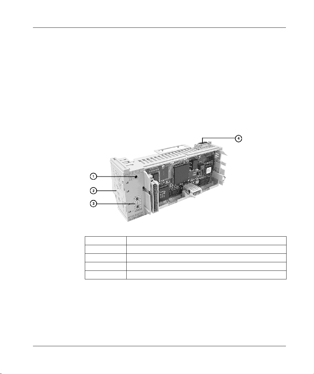
Overview of Momentum Option Adapters
Front Panel Components of the Momentum Modbus Plus Option Adapter
Overview
The front panel includes:
z An LED indicator
z Battery compartment
z Address switches
z 9-pin D-shell connector for Modbus Plus communications
Illustration
The illustration below shows the LED indicator, address switches, Modbus Plus
connector, and battery compartment.
68
Legend:
Label Description
1 LED indicator
2 Battery compartment door
3 Address switches for Modbus Plus
4 9-pin D-shell connector for Modbus Plus communications
31002674 4/2010
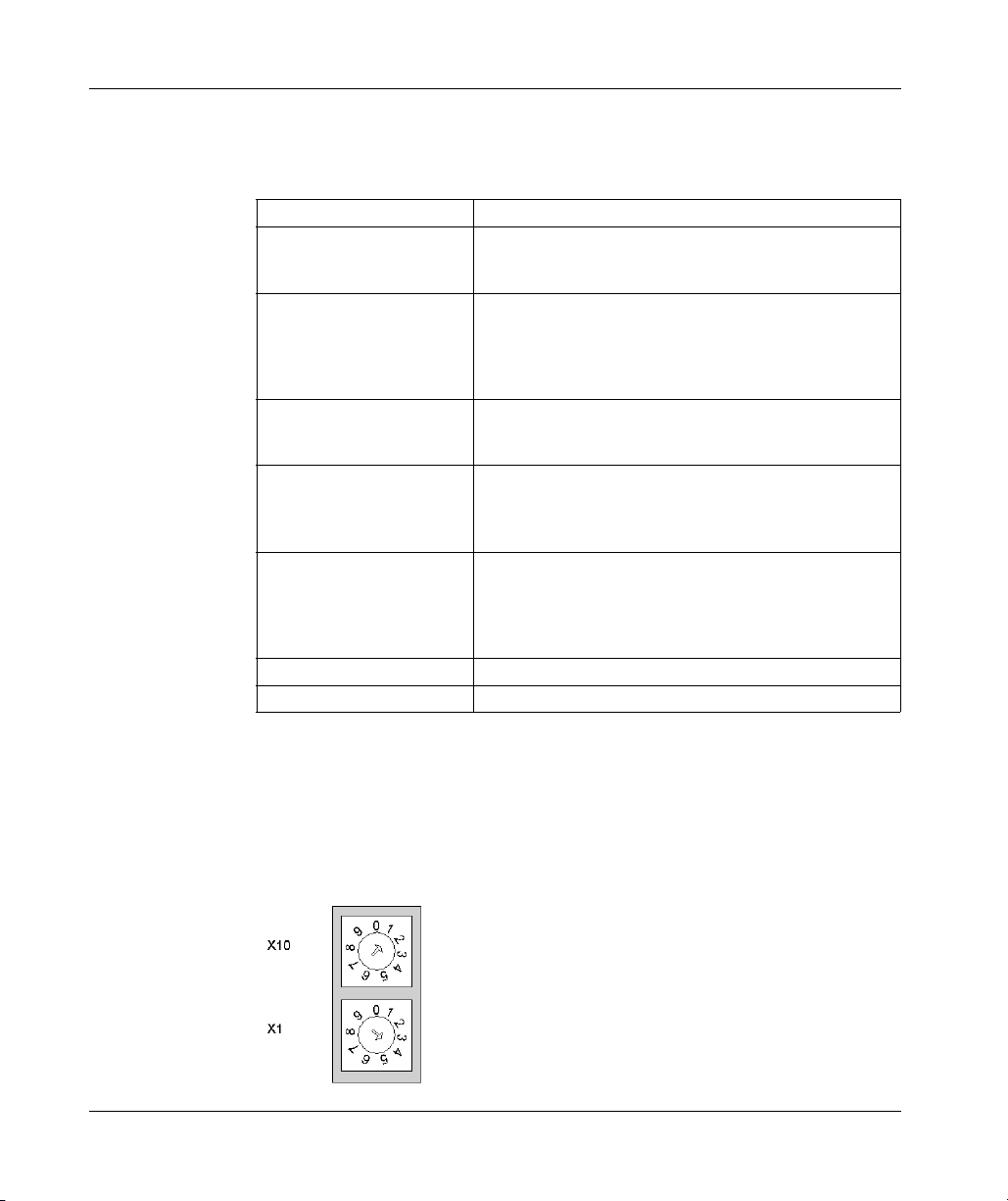
LED Indicator
Overview of Momentum Option Adapters
This option adapter has one LED indicator, the MB+ ACT indicator. This indicator
flashes the following patterns, based on the status of the Modbus Plus node:
Pattern Meaning
6 flashes/s This is the normal operating state for the node. It is receiving
and passing the network token. All nodes on a healthy
network flash this pattern.
1 flash/s The node is offline just after power-up or after exiting the 6
flashes/s mode. In this state, the node monitors the network
and builds a table of active nodes. After being in this state for
5s, the node attempts to go to its normal operating state,
indicated by 6 flashes/s.
2 flashes, then OFF for 2s The node detects the token being passed among the other
nodes, but never receives the token. Check the network for
an open circuit or defective termination.
3 flashes, then OFF for 1.7s The node is not detecting any tokens being passed among
the other nodes. It periodically claims the token but cannot
find another node to which to pass it. Check the network for
an open circuit or defective termination.
4 flashes, then OFF for 1.4s The node has detected a valid message from a node using a
network address identical to its own address. The node
remains in this state for as long as it continues to detect the
duplicate address. If the duplicate address is not detected for
5s, the node changes to its 1 flash/s mode.
ON Indicates an invalid node address.
OFF Possible fault with Modbus Plus Option Adapter.
Modbus Plus Address Switches
The two rotary switches on the option adapter are used to set a Modbus Plus node
address for the CPU module. The switches are shown in the following illustration.
Their usage is described in detail in Modbus Plus Addresses in Networks with
Momentum Components, page 142.
The switches in this illustration are set to address 14.
31002674 4/2010 69

Overview of Momentum Option Adapters
Specifications of the Momentum Modbus Plus Option Adapter
172 PNN 210 22 Serial Option Adapter Specifications
Mechanical
Weight 85.05 g (3 oz.)
Dimensions (HxDxW) 58.3 (on battery side) x 60.6 x 143.1 mm
(2.27 x 2.36 x 5.57 in)
Material (enclosures/bezels) Lexan
Time-of-Day Clock
Accuracy +/- 13 s/day
Battery one 2/3 AA lithium required; included in a separate
Service Life < 30 days from the time a battery-low indication is received
Shelf Life In excess of 5 yr. @ room temperature
Operating Conditions
Temperature 0 ... 60 degrees C
Humidity 5 ... 95% (noncondensing)
Chemical Interactions Enclosures and bezels are made of Lexan, a
Altitude, full operation 2000 m (6500 ft)
Vibration 10 ... 57 Hz @ 0.075 mm displacement amplitude
Shock +/-15 g peak, 11ms, half sine wave
RFI susceptibility/immunity Meets CE mark requirements for open equipment.
Storage Conditions
Temperature -40...+85 degrees C
Humidity 5 ... 95% (noncondensing)
Safety Parameters
Degree of Protection Unintentional access (UL 508 Type 1, NEMA250 Type 1,
Di-electric Strength RS232/485 is non-isolated from logic common
Ground Continuity 30 A test on the exposed metal connector
Agency Approvals UL 508, CSA, CUL, CE
package with the option adapter
to actual battery failure @ 40 degrees C maximum ambient
temperature with the system continuously powered down.
polycarbonate that can be damaged by strong alkaline
solutions
57...150 Hz @ 1 g
Ref. IEC 68-2-6 FC
Ref. IEC 68-2-27 EA
Open equipment should be installed in an industrystandard enclosure, with access restricted to qualified
service personnel.
IP20 conforming to IEC529)
70
31002674 4/2010

Overview of Momentum Option Adapters
2.4 Redundant Modbus Plus Option Adapter (A Momentum Component)
Purpose
This section describes the 172 PNN 260 22 Redundant Modbus Plus option adapter,
including the front panel components and specifications.
What's in this Section?
This section contains the following topics:
Topic Page
Front Panel Components of the Momentum Redundant Modbus Plus Option
Adapter
Specifications of the Momentum Redundant Modbus Plus Option Adapter 75
72
31002674 4/2010 71
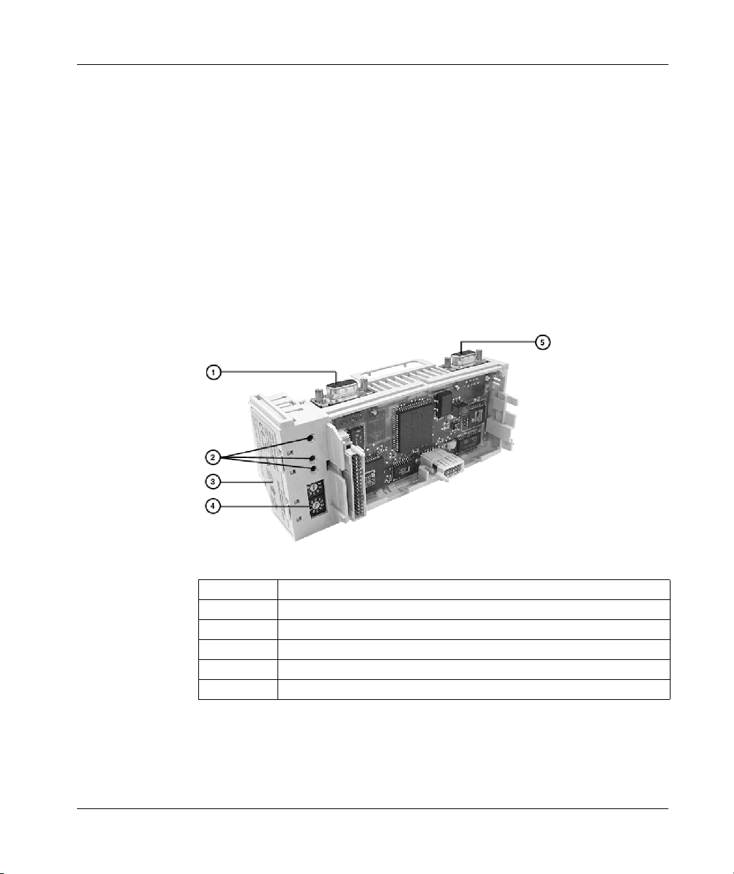
Overview of Momentum Option Adapters
Front Panel Components of the Momentum Redundant Modbus Plus Option Adapter
Overview
The front panel includes:
z Two 9-pin D-shell connectors for Modbus Plus communications
z Three LED indicators
z Battery compartment
z Address switches
Illustration
The illustration below shows the LED indicators, address switches, battery
compartment and Modbus Plus connectors.
72
Legend:
Label Description
1 9-pin D-shell connector for Modbus Plus port B
2 Array of three LED indicators
3 Battery compartment door
4 Address switches for Modbus Plus
5 9-pin D-shell connector for Modbus Plus port A
31002674 4/2010

LED Indicators
This option adapter has three LED indicators. Their functions are described in the
table below.
LED Status Function
MB+ ACT Green Indicates activity on one or both of the Modbus Plus ports (see
ERR A Red Indicates a communications failure on Modbus Plus port A*
ERR B Red Indicates a communications failure on Modbus Plus port B*
* If you are not using redundant cabling on the Modbus Plus link (i.e., if only one of the ports
is being used) the Error LED for the unused port will be on constantly when Modbus Plus
communication occurs on the network.
MB+ ACT Flash Patterns
This table provides the patterns that the MB+ ACT indicator will flash to indicate the
status of the Modbus Plus node.
Pattern Meaning
6 flashes/s This is the normal operating state for the node. It is receiving and passing
1 flash/s The node is offline just after power-up or after exiting the 6 flashes/s mode.
2 flashes, then
OFF for 2s
3 flashes, then
OFF for 1.7s
4 flashes, then
OFF for 1.4s
ON Indicates an invalid node address.
OFF Possible fault with Modbus Plus option adapter.
Overview of Momentum Option Adapters
the flash pattern table below)
Off No activity on either Modbus Plus port
Off No problems detected on Modbus Plus port A
Off No problems detected on Modbus Plus port B
the network token. All nodes on a healthy network flash this pattern.
In this state, the node monitors the network and builds a table of active
nodes. After being in this state for 5s, the node attempts to go to its normal
operating state, indicated by 6 flashes/s.
The node detects the token being passed among the other nodes, but
never receives the token. Check the network for an open circuit or
defective termination.
The node is not detecting any tokens being passed among the other
nodes. It periodically claims the token but cannot find another node to
which to pass it. Check the network for an open circuit or defective
termination.
The node has detected a valid message from a node using a network
address identical to its own address. The node remains in this state for as
long as it continues to detect the duplicate address. If the duplicate
address is not detected for 5s, the node changes to its 1flash/s mode.
31002674 4/2010 73

Overview of Momentum Option Adapters
Modbus Plus Address Switches
The two rotary switches on the option adapter are used to set a Modbus Plus node
address for the CPU module. The switches are shown in the following illustration.
Their usage is described in detail in Modbus Plus Addresses in Networks with
Momentum Components, page 142.
The switches in this illustration are set to address 14.
Modbus Plus Ports A and B
This option adapter has two Modbus Plus ports. Redundant cabling on the Modbus
Plus network offers increased protection against cable faults or excessive noise
bursts on either one of the two cable paths. When one of the channels experiences
communication problems, error-free messaging can continue to be processed on
the alternate path.
74
31002674 4/2010

Overview of Momentum Option Adapters
Specifications of the Momentum Redundant Modbus Plus Option Adapter
172 PNN 260 22 Redundant Modbus Plus Option Adapter Specifications
Mechanical
Weight 85.05 g (3 oz)
Dimensions (HxDxW) 58.3 (on battery side) x 60.6 x 143.1mm
(2.27 x 2.36 x 5.57 in)
Material (enclosures/bezels) Lexan
Time-of-Day Clock
Accuracy +/-13 s/day
Battery one 2/3 AA lithium required; included in a separate
package with the option adapter
Service Life < 30 days from the time a battery-low indication is
Shelf Life In excess of 5 yr. @ room temperature
Operating Conditions
Temperature 0 ... 60 degrees C
Humidity 5 ... 95% (noncondensing)
Chemical Interactions Enclosures and bezels are made of Lexan, a
Altitude, full operation 2000 m (6500 ft)
Vibration 10 ... 57 Hz @ 0.075 mm displacement amplitude
Shock +/-15 g peak, 11 ms, half sine wave
RFI susceptibility/immunity Meets CE mark requirements for open equipment.
Storage Conditions
Temperature -40...+85 degrees C
Humidity 5 ... 95% (noncondensing)
Safety Parameters
Degree of Protection Unintentional access (UL 508 Type 1, NEMA250 Type 1,
Di-electric Strength RS232/485 is non-isolated from logic common
Ground Continuity 30 A test on the exposed metal connector
Agency Approvals UL 508, CSA, CUL, CE
received to actual battery failure @ 40 degrees C
maximum ambient temperature with the system
continuously powered down.
polycarbonate that can be damaged by strong alkaline
solutions
57...150 Hz @ 1 g
Ref. IEC 68-2-6 FC
Ref. IEC 68-2-27 EA
Open equipment should be installed in an industrystandard enclosure, with access restricted to qualified
service personnel.
IP20 conforming to IEC529)
31002674 4/2010 75

Overview of Momentum Option Adapters
76
31002674 4/2010

Purpose
Assembling Momentum Components
31002674 4/2010
Assembling
Momentum Components
3
This chapter describes how to assemble and disassemble a Momentum M1 CPU,
using the following components:
z processor adapter
z I/O base
z option adapter
z label
It also describes how to install the battery in the option adapter.
What's in this Chapter?
This chapter contains the following sections:
Section Topic Page
3.1 Assembling an M1 CPU with an I/O Base 78
3.2 Assembling an M1 CPU with a Momentum Option Adapter 84
3.3 Installing Batteries in a Momentum Option Adapter 92
3.4 Labeling the M1 CPU 95
31002674 4/2010 77

Assembling Momentum Components
3.1 Assembling an M1 CPU with an I/O Base
Purpose
This section describes how to assemble a processor adapter with an I/O base and
how to disassemble them.
What's in this Section?
This section contains the following topics:
Topic Page
Assembling a Processor Adapter onto an I/O Base 79
Disassembling a Momentum Processor from an I/O Base 82
78
31002674 4/2010

Assembling a Processor Adapter onto an I/O Base
General Description
CAUTION
ADAPTER MAY BE DAMAGED BY STATIC ELECTRICITY
z Use proper electrical static discharge (ESD) procedures when handling the
adapter.
z Do not touch the internal elements.
The adapter's electrical elements are sensitive to static electricity.
Failure to follow these instructions can result in injury or equipment damage.
DANGER
RISK OF ELECTRICAL SHOCK
z Ensure that the I/O base is not under power when it does not have an adapter
mounted on it.
z To make sure that power is not present, do not insert the wiring connectors to
the I/O base until after the adapter has been mounted.
Electrical circuitry on the I/O base may be exposed when a Momentum adapter is
not mounted.
Failure to follow these instructions will result in death or serious injury.
Assembling Momentum Components
An Ethernet communication adapter can be snapped directly onto a Momentum I/O
base, making connections at three points:
z The plastic snap extensions on the two sides of the Momentum 170ENT11001
unit fit into the two slots on the sides of the I/O base.
z The 12-pin connectors on the two units mate together.
z The grounding screw is secured.
The components can be snapped together by hand; no assembly tools are required.
For a detailed description of installation procedures and grounding considerations,
refer to the Momentum I/O Base User Guide (870 USE 002).
31002674 4/2010 79
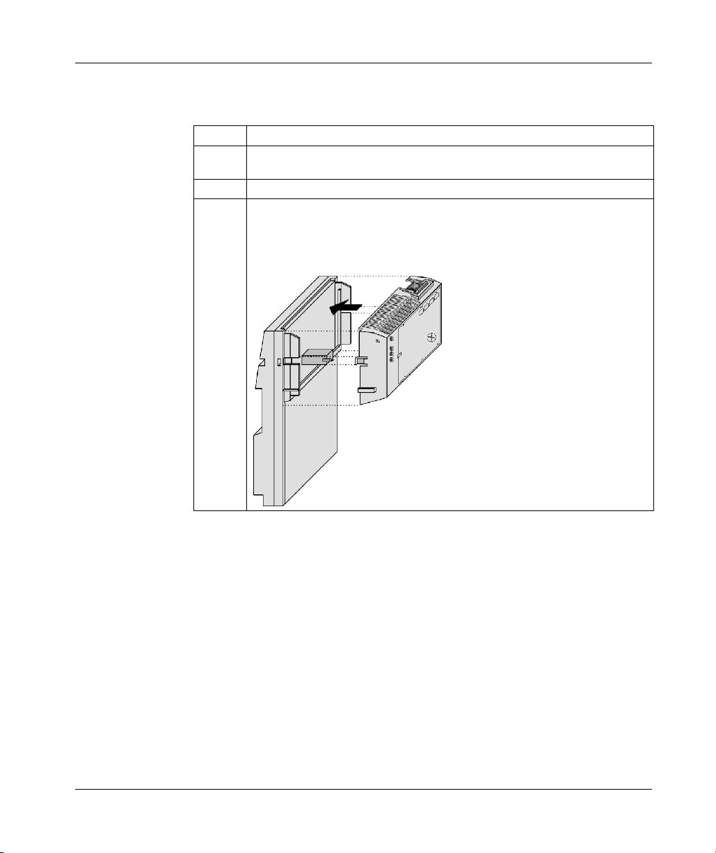
Assembling Momentum Components
Procedure: Assembling an Adapter and an I/O Base
Follow the steps below to assemble an adapter and an I/O base.
Step Action
1 Choose a clean environment to assemble the I/O base and adapter to protect the
circuitry from contamination.
2 Make sure that the I/O base is not under power when you assemble the module.
3 Align the two plastic snap extensions on the adapter with the slots on the sides of
the I/O base. The 12-pin connectors will automatically line up when the units are
in this position. The two devices should be oriented so their communication ports
are facing out, on the back side of the assembly.
80
31002674 4/2010
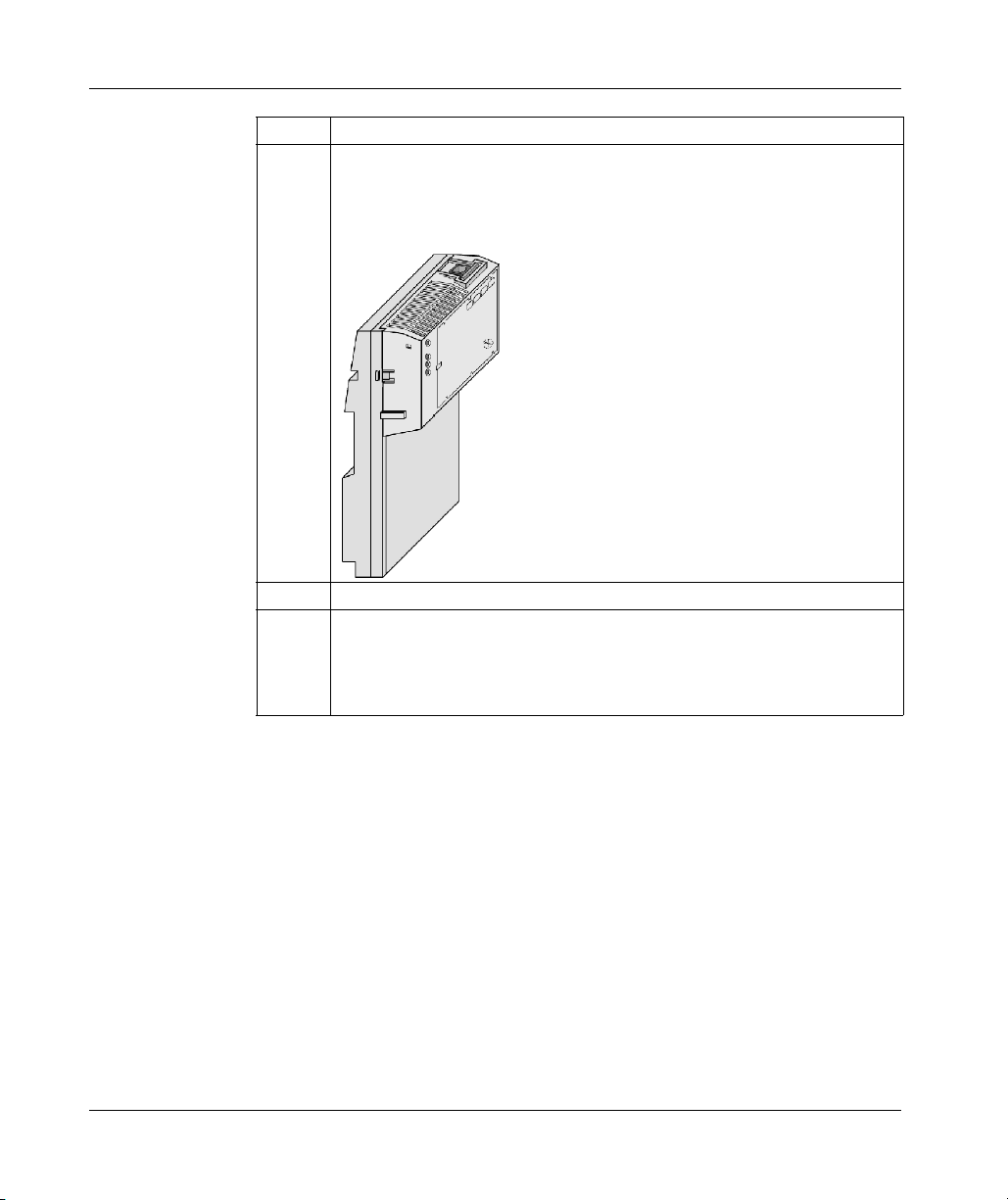
Assembling Momentum Components
Step Action
4 Push the adapter onto the base, gently pressing the locking tabs inward.
Result: The locking tabs on each side of the adapter slide inside the I/O base and
out through the locking slot. The 12-pin connectors on the two units are mated to
each other in the process.
5 Attach the grounding screw.
6 Once the adapter has been assembled and snapped onto a base and the
grounding screw secured, the entire assembly can be mounted on a DIN rail or
panel. The device meets CE mark requirements for open equipment. Open
equipment should be installed in an industry-standard enclosure, and direct
access must be restricted to qualified service personnel.
31002674 4/2010 81

Assembling Momentum Components
Disassembling a Momentum Processor from an I/O Base
Tool
Use a flat-head screw driver.
Removing an Adapter from an I/O Base
DANGER
RISK OF ELECTRICAL SHOCK
z Ensure that the I/O base is not under power when it does not have an adapter
mounted on it.
z To make sure that power is not present, do not insert the wiring connectors to
the I/O base until after the adapter has been mounted.
Electrical circuitry on the I/O base may be exposed when a Momentum adapter is
not mounted.
Failure to follow these instructions will result in death or serious injury.
Step Action
1 Choose a clean environment to disassemble the unit, in order to protect the circuitry
from contamination.
2 Make sure that the I/O base is not under power by removing the terminal connectors
from the I/O base.
3 Remove the grounding screw.
82
31002674 4/2010
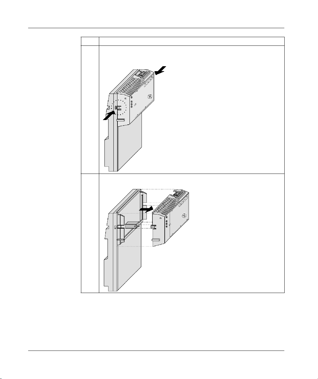
Assembling Momentum Components
Step Action
4 Use a screwdriver to push the locking tabs on both sides of the adapter inward, as
shown in the illustration below.
5 Lift adapter straight up and away from base, maintaining pressure on locking tabs.
31002674 4/2010 83

Assembling Momentum Components
3.2 Assembling an M1 CPU with a Momentum Option Adapter
Purpose
An option adapter may only be used in conjunction with a processor adapter. It may
not be used alone with an I/O base.
This section describes how to add an option adapter when assembling a Momentum
module and how to remove an option adapter from the assembled module.
What's in this Section?
This section contains the following topics:
Topic Page
Assembling an M1 Processor Adapter and a Momentum Option Adapter 85
Mounting the Assembled Adapters on the I/O Base 87
Disassembling a Momentum Module with an Option Adapter 89
84
31002674 4/2010

Assembling Momentum Components
Assembling an M1 Processor Adapter and a Momentum Option Adapter
Overview
If a Momentum option adapter is used, it is mounted between a Momentum M1
processor adapter and a Momentum I/O base in a three-tiered stack.
This section contains guidelines, safety precautions and a procedure for assembling
a processor adapter and an option adapter.
The next section describes how to mount the assembled adapters on an I/O base.
Guidelines
We recommend that you snap together the option adapter and the M1 processor
adapter before mounting them on the I/O base.
Connection Points Between Adapters
The option adapter and M1 processor connect at these four points:
z The plastic snap extensions on the two sides of the M1 fit into the two slots on the
sides of the option adapter
z The 12-pin connectors on the center of the back walls of the two units mate
together
z The 34-pin processor extension connectors that run along the left sidewalls of the
components mate together
No Tools Required
The components can be snapped together by hand; no assembly tools are required.
A flat-head screw driver is required to disassemble the unit.
31002674 4/2010 85
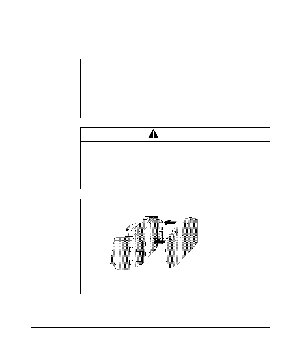
Assembling Momentum Components
Procedure: Assembling an Option Adapter and Processor
Follow the steps in the table below to assemble an option adapter and an M1
processor.
Step Action
1 Choose a clean environment to assemble the option adapter and processor to
protect the circuitry from contamination.
2 Align the two plastic snap extensions on the sides of the M1 processor adapter
with the slots on the sides of the option adapter.
The 12-pin connectors and processor extension connectors will automatically
line up when the units are in this position. The two devices should be oriented
so that their communication ports are facing out on the back side of the
assembly.
CAUTION
PIN ALIGNMENT
Proper assembly requires that the 34 pins on the processor extension connector
be aligned correctly with the mating socket on the M1 processor adapter.
z Align pins exactly.
z Do not connect one side and try to rotate the M1 onto the option adapter.
Failure to follow these instructions can result in injury or equipment damage.
86
3 Push the processor adapter onto the option adapter, gently pressing the locking
tabs inward.
Result: The locking tabs on each side of the processor adapter slide inside the
option adapter and out through the locking slot. The 12-pin and 34-pin
connectors on the two units are mated to each other in the process.
31002674 4/2010

Mounting the Assembled Adapters on the I/O Base
Overview
This section gives guidelines, safety precautions and a procedure for mounting the
assembled processor and option adapter on an I/O base.
Guidelines
CAUTION
EXPOSED ELECTRICAL CIRCUITRY
Electrical circuitry on the I/O base may be exposed when an adapter is not
mounted.
z Ensure that power is not present.
z Mount the adapter onto the I/O base before inserting the wiring connectors.
If an I/O base has no Momentum adapter mounted:
z Ensure that the I/O base receives no power.
When more than one connector is attached to the I/O base:
z Remove all connectors to prevent the unit from receiving power from an
unexpected source.
Failure to follow these instructions can result in injury or equipment damage.
Assembling Momentum Components
The assembled adapters connect with the I/O base at these seven points:
z Two plastic snaps on the front of the option adapter fit into two slots on the front
of the I/O base.
z The plastic snap extensions on the two sides of the option adapter fit into the two
slots on the sides of the I/O base.
z The 12-pin connectors on the center of the back walls of the two units mate
together.
z The plastic stirrup on the back of the option adapter clips onto the bottom of the
I/O base.
Mounting the Assembled Adapters on an I/O Base
Follow the steps in the table below to mount the assembly on an I/O base.
Step Action
1 Be sure that the I/O base is not under power when you assemble the module.
31002674 4/2010 87

Assembling Momentum Components
Step Action
2 Align the four plastic snap extensions (on the front and sides of the option adapter)
with the slots on the I/O base.
The 12-pin connectors will automatically line up when the units are in this position.
The devices should be oriented such that their communication ports are facing out
on the back side of the assembly.
3 Push the assembled adapters onto the base, gently pressing the locking tabs inward.
Snap #1 shown in the illustration below will not align properly with the mating slot in
the I/O base unless the option adapter is placed straight onto the base. Do not attach
just one latch and rotate the option adapter onto the I/O base.
88
Result: The locking tabs on each side of the option adapter slide inside the I/O base
and out through the locking slot. The 12-pin connectors on the two units are mated
to each other in the process.
31002674 4/2010

Assembling Momentum Components
Disassembling a Momentum Module with an Option Adapter
Overview
The three-tiered assembly is designed to fit together tightly so it can withstand shock
and vibration in an operating environment. This section contains two procedures:
z Removing the assembled adapters from the I/O base
z Removing the option adapter from the processor
Tools Required
Flat-head screwdriver.
Procedure: Removing the Adapter Assembly from the I/O Base
Follow the steps in the table below to remove the assembled option adapter and M1
processor adapter from the I/O base.
Step Action
1 Make sure that the power is off by removing the terminal connectors from the I/O
base.
2 Remove the assembled unit from its wall or DIN rail mounting surface.
CAUTION
EXPOSED CIRCUITRY IN BATTERY COMPARTMENT
When you open a battery compartment, electrical circuitry can be exposed and can
be damaged by a flat-head screwdriver inserted into the compartment.
z Use care when you insert a screwdriver in the battery compartment.
z Avoid scratching any exposed elements.
Failure to follow these instructions can result in injury or equipment damage.
31002674 4/2010 89

Assembling Momentum Components
3 Open the battery door and use a flat-head screwdriver to release snaps 1 and 2
4 Once snaps 1 and 2 have been disengaged, use the screwdriver to release
5 Gently lift the stirrup on the back of the option adapter with your fingers until it
as shown in the illustration below.
snaps 3 and 4 on the front of the assembly.
disengages from the bottom of the I/O base. Then lift the option adapter and M1
assembly from the I/O base.
90
31002674 4/2010
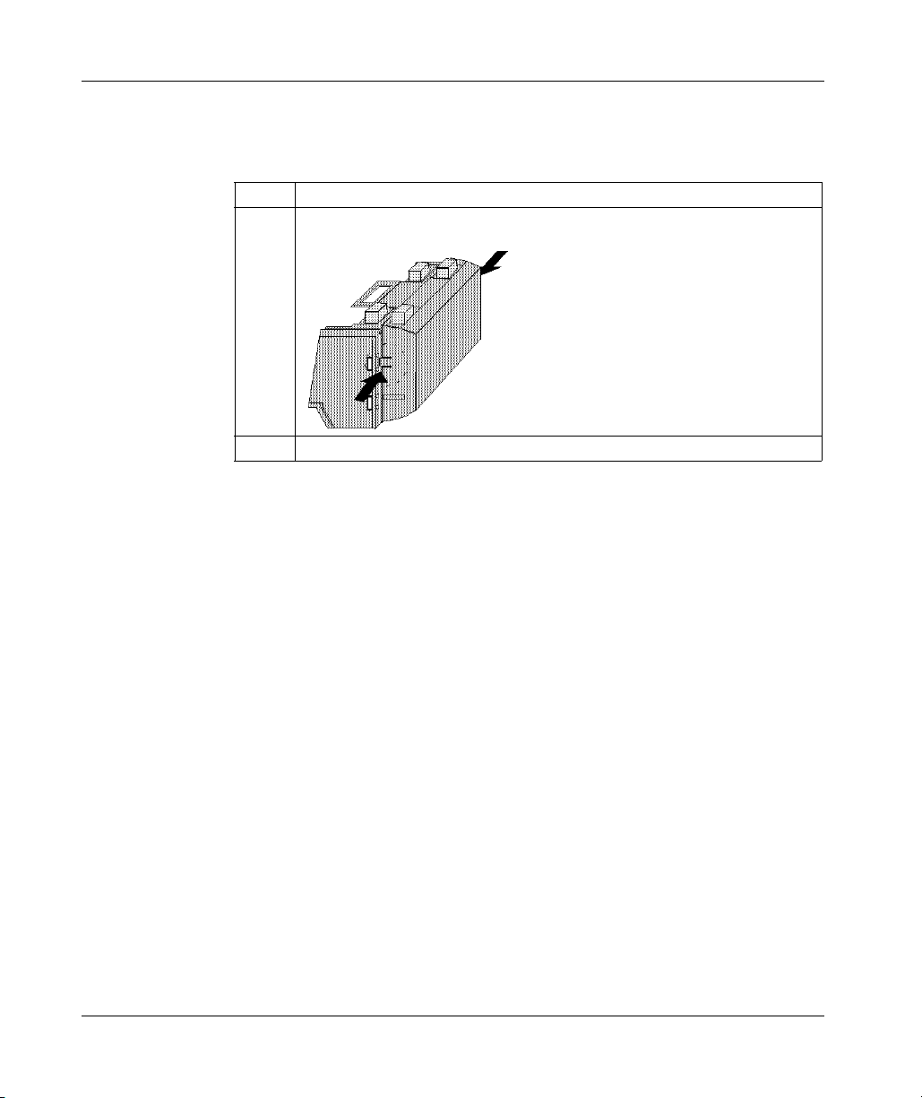
Procedure: Disassembling an Option Adapter and M1 Processor
Follow the steps in the table below to remove the option adapter from the M1
processor.
Step Action
1 Use a screwdriver to push the clips on both sides of the adapter inward.
2 Lift off the adapter.
Assembling Momentum Components
31002674 4/2010 91

Assembling Momentum Components
3.3 Installing Batteries in a Momentum Option Adapter
Installation Guidelines
Why Install the Battery?
If you are using a Momentum option adapter in your CPU assembly, you have a
battery-backup capability. The battery maintains user logic, state RAM values and
the TOD clock in the event that the CPU loses power.
What Kind of Battery?
CAUTION
ELECTRONIC CIRCUITRY EXPOSED
When the battery door is open, electronic circuitry is exposed.
z Follow proper electrical static discharge (ESD) measures while handling the
equipment during battery maintenance.
Failure to follow these instructions can result in injury or equipment damage.
92
One 2/3 AA lithium battery needs to be installed in the compartment on the side of
the option adapter.
Each module is shipped with a battery. You must install this battery.
Please see the appendices for an explanation of battery life.
31002674 4/2010

Installing the Battery
Assembling Momentum Components
When installing the battery, observe correct polarity, as indicated on the
compartment door.
Leave Power On When Changing the Battery
Once your CPU has been commissioned and is running, maintain power to the
module whenever you change the battery.
Unless you save to flash, you will need to reload the user logic program from the
original files if you change the battery while the power is OFF.
31002674 4/2010 93
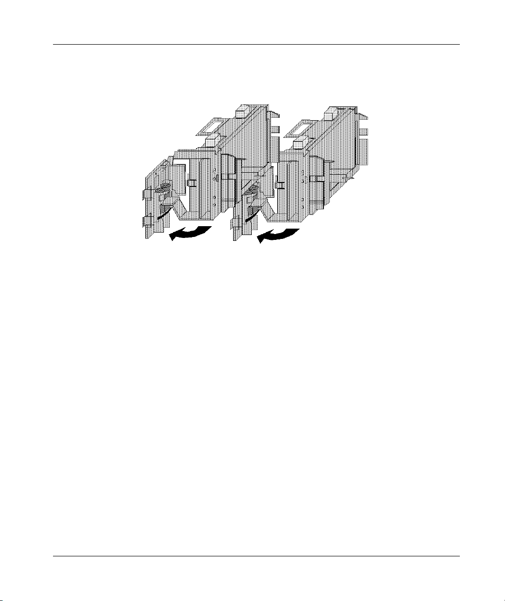
Assembling Momentum Components
Removing and Replacing the Battery
Battery maintenance should be performed only by qualified personnel according to
the following illustration.
Monitor the Battery
Because a Momentum CPU assembly is designed to be installed in a cabinet where
it cannot be seen at all times, no LED was created to monitor health.
We recommend that you reserve a battery coil in your programming panel software
configuration and use it to monitor the health of your battery and report the need for
replacement prior to battery failure. (Refer to Reserving and Monitoring a Battery
Coil with Modsoft for Momentum Option Adapters, page 186 for Modsoft or
Reserving and Monitoring a Battery Coil, page 275 for Concept.)
94
31002674 4/2010

Assembling Momentum Components
3.4 Labeling the M1 CPU
Guidelines for Labeling the Momentum Processor Adapter
Fill-In Label
A fill-in label is shipped with each I/O base. This label should be placed on the
Momentum processor adapter that you mount on that base.
A completed label provides information about the assembled module and its I/O field
devices that can be used by service and maintenance personnel.
The model number of the I/O base is marked on the fill-in label directly above the
color code. The cutout area above the I/O model number allows the model number
of the adapter to show through.
NOTE: An option adapter may also be used in the assembled module. You will find
its model number printed in the upper left corner of adapter housing.
Example
A fill-in label is illustrated in the illustration below.
1 fields for plant name, station name and network address
2 cutout: the model number of the adapter shows through
3 model number of the I/O base
4 color code of the I/O base
5 short description of the I/O base
6 field for the symbol name of inputs
7 field for the symbol name of outputs
31002674 4/2010 95

Assembling Momentum Components
96
31002674 4/2010

Purpose
What's in this Part?
Communication Ports
31002674 4/2010
Communication Ports on Momentum Components
II
This part describes the communication ports available with Momentum processor
adapters and option adapters.
This part contains the following chapters:
Chapter Chapter Name Page
4 Using the Modbus Ports for Momentum Components 99
5 Using the Modbus Plus Ports with Momentum Components 127
6 Using the Ethernet Port on Selected M1 Processor Adapters 147
7 Using the I/O Bus Port for Networks Momentum Components 161
31002674 4/2010 97

Communication Ports
98
31002674 4/2010

Using the Modbus Ports
31002674 4/2010
Using the Modbus Ports for Momentum Components
Purpose
This chapter describes Modbus port 1 and Modbus port 2, including communication
parameters, cabling guidelines for Modbus RS485 networks, cable accessories and
pinouts.
What's in this Chapter?
This chapter contains the following sections:
4.1 Modbus Port 1 (on Selected M1 Processor Adapters) 100
4.2 Modbus Port 2 (On Selected Momentum Components) 106
4
Section Topic Page
31002674 4/2010 99

Using the Modbus Ports
4.1 Modbus Port 1 (on Selected M1 Processor Adapters)
Purpose
Modbus port 1 is standard on all Momentum M1 processor adapters, except the
Ethernet processor adapters. This section describes the port, the recommended
cable accessories and the connection pinouts.
What's in this Section?
This section contains the following topics:
Modbus Port 1 (On Selected M1 Processor Adapters) 101
Cable Accessories for Modbus Port 1 on M1 Processor Adapters 103
Pinouts for Modbus Port 1 on M1 Processor Adapters 104
Topic Page
100
31002674 4/2010
 Loading...