

Page 1

WITH EYE
USER MANUAL
Page 2
WITH EYE
TABLE OF CONTENTS
IMPOR TANT S AFET Y GUID ELIN ES 1
OPERATION GUI DE / S TART U P 2
COMPR ESSE D AIR TANK WARNIN GS 3
INSTALLIN G CO MPRE SSED A IR TANK 4
PROPE R USE OF B ARRE L BLOCK ING DE VICE 4
BATT ERY INSTALLATION 4-5
BATT ERY CHAR GING 5
ELECT RONICS & S ETTI NGS 5-7
TRIGG ER ADJUST MENT 7
VELOCITY ADJ USTM ENT 7-8
C/A ON/OFF ADAPTER 8
REGUL ATOR ADJUST MENT 9
DISAS SEMBLE / R EASS EMBLE AND CLEANI NG O F RE AR INT ERNA LS 9-10
PAINTBALL JAM / A NTI CH OP E YES / CHAN GING BAL L STOPPER 10 -11
CUP S EAL RE MOVAL 12-1 3
REGUL ATOR MAI NTENAN CE / SCH EMATI C 13
MISC TROUBL ESHO OTING / AIR L EAKS 13-14
WARRAN TY STATEMENT 14
RSX PART S LIST 15
RSX SCHEM ATIC 1 6
Page 3

IM PORTANT SAFETY GUIDELINES
WARNING
• This paintball marker is NOT a toy. It can cause serious injury or death.
• Kingman recommends that the customer be at least 18 years of age to purchase this product.
• Read this manual and air tank warnings before using this product.
• Any modications or tampering of original factory parts will void all warranties and liabilities from Kingman.
• Kingman recommends using a barrel blocking device when the marker is not in operation.
• To ensure proper adjustment of velocity (fps), Kingman strongly recommends using a chronograph for paintball
use located at most paintball stores and paintball elds.
• Before / after use of the marker, make sure to fasten all screws. Screws may become loose due to vibration.
Loose screws can be dangerous and cause injury.
• Kingman STRONGLY recommends that any person using this product or within range of this product while it is
in use MUST wear EYE/FACE PROTECTION designed specically for the sport of paintball. This includes, but is not
limited to, performing a maintenance check and during target practice.
• Kingman reminds the user that it is YOUR RESPONSIBILITY to protect your eyes/face at all times, and will not
be held liable for injuries sustained when failing to wear the appropriate protection.
• Never shoot or point your marker at a person that is not in a designated paintball facility and without proper
paintball protection.
• Treat every paintball marker as if it were loaded.
• Never look down the barrel of a loaded or unloaded marker.
• Always keep the paintball marker in SAFE or OFF mode until ready to operate.
• Always remove the gas source before disassembly.
• Fire only 0.68 caliber paintballs with this product.
• Always make certain the bolt is in the un-cocked position when marker is not in use.
• Using a paintball marker outside of a non designated paintball eld can be illegal, and is subject to law
enforcement penalties if property damage is caused by the user.
• Transfer this instruction manual upon change of marker ownership.
OP ERATI ON GUIDE / STAR T UP
WARNING: Always keep the marker powered OFF or on SAFE until you are ready to re.
1. Always attach a barrel blocking device over the tip of the barrel for safety precautions when the marker is not in use.
2.
Install and charge the battery see pages (see Battery Charging / Installation).
3. Attach the Compressed Air Tank to the C/A On/Off adapter. HEL PFUL TIP : Make sure to have the Compressed Air
Tank lled before attaching to the marker. Tighten the Compressed Air Tank clockwise in the markers C/A On/Off
adapter until it is snug. If an air leak occurs between the tank and the C/A On/Off adapter, replace the urethane bottle
O-ring. NOTE: O-rings in the markers parts kit are not supplied to attach with a Compressed Air Tank. IMPORTANT:
You should never need to use any hand tool to attach a Compressed Air Tank to the C/A On/Off adapter.
4. Attach an electronic loader on the Twist Clamp (#FND021) twist clockwise to fasten and counter clockwise to release
the loader. Only use .68 caliber paintballs through the loader. NOTE: Kingman recommends that you use a force feed /
high speed electronic loader to reach optimum performance.
5. Cocking the marker. Pull the Top Cocking Knob (#STK001) rearward until the Delrin bolt latches. CAUTION: Should
you let go of the Top Cocking Knob before it latches, your marker may re.
6. Remove the barrel blocking device. CAUTION: With the power switch turned ON the marker is LIVE. Pulling the
trigger (#TRS005) will re a paintball. IMPORTANT: Only test your marker in a safe direction or in a designated
playing eld.
7. Performing a velocity (fps) check. Turning the Velocity Adjuster / Spring Guide (#VTA021) clockwise will increase
the velocity (fps) while turning counter-clockwise will decrease the velocity (fps). NOTE: This marker is equipped
with a Regulator dial that can adjust the pressure from 0-600psi. (see Regulator Adjustment) NOTE: Your marker is
intended to be used in a paintball facility with the proper paintball protection. IMPORTANT: Kingman recommends
using a chronograph to ensure that the maker’s velocity is under 300 (fps).
8. When nished playing, remove all paintballs from the paintball loader before detaching from the markers feed neck.
CAUTION: There may be a paintball in the marker’s breach; take a couple of shots in a safe direction to make sure the
barrel and receiver are empty.
9. Place the barrel blocking device over the barrel tip. This will help avoid any accidental discharge.
10. Kingman recommends having the marker in the “SAFE or OFF” position after use.
11. Unscrew the Compressed Air Tank from the marker’s C/A On/Off adapter. Turning the tank counter-clockwise will
detach it from the marker’s C/A On/Off adapter. CAUTION: Never expose any skin underneath the C/A On/Off
adapters bleed hole when removing the tank. This can run the risk of getting skin burn from the releasing of the GAS.
IMPORTANT: You should never need to use any hand tool to detach a Compressed Air Tank.
12.
Store the marker in a paintball bag or in a safe place. WARNING: Before / after use of the marker, make sure to fasten
all screws. Screws can become loose due to vibration. Loose screws can be dangerous and cause injury. HELPFUL
TIP: It’s a good practice to lubricate your marker before and after each use, especially when storing the marker for
an extended period of time. Add a few drops of paintball gun oil or marker grease on the Striker O-ring (#ORG001)
(see Disassemble / Reassemble). Before storing the marker, make sure the marker is in the un-cocked position. This
will help the main spring maintain its tension.
IM PORTANT
• Firing velocity may vary according to altitude and climate conditions.
• Before using your marker in play, you must always rst perform a “SAFE VELOCITY TEST”. This can only be
accomplished by using a testing device called a “Velocity Chronograph“ and can be performed at a paintball dealership
or local playing eld.
• NOTE: This product is intended to be used at a velocity no greater than 300 feet per second (fps). This product is
NOT intended to be used at any distance less than 25 feet.
• This paintball marker may have excess gas after the removal of the Compressed Air Tank. Please remove all paintballs
and discharge the remaining gas safely.
• Never store a Compressed Air Tank attached on the marker while not supervised.
1 2
Page 4
COMPRESSED AIR TAN K WARNINGS
IN STALL ING A COMPRESSED AIR TANK
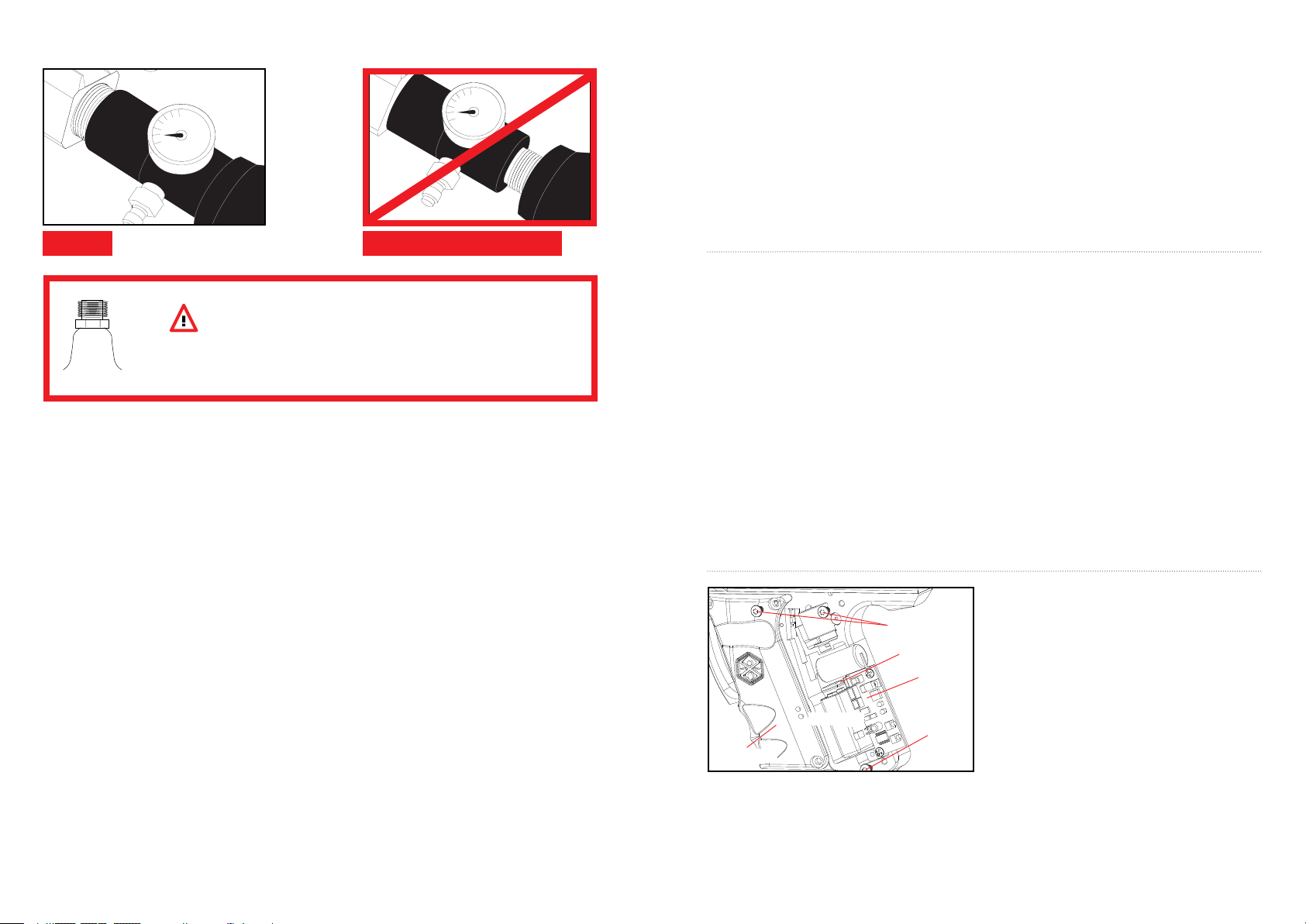
Firmly screw the Compressed Air Tank clockwise into the markers C/A On/Off adapter (#ASA020). HELPFUL TIP:
Before installing a Compressed Air Tank, make sure that the tank is full and that it has a urethane bottle on the top of
the valve to prevent air leaks. IMPORTANT: You should never need to use any hand tool to attach a Compressed Air
Tank to the C/A On/Off adapter.
RE MOVI NG THE COMPRESSED AIR TAN K
Firmly unscrew the Compressed Air Tank by turning the tank counter-clockwise until it comes out of the C/A On/Off
adapter. HELPFUL TIP: After ring the marker, you should ALWAYS remove the Compressed Air Tank before storing.
When the tank is being removed, excess air will release from the C/A On/Off adapter (#ASA0020). CAUTION: Never
expose any skin to the C/A On/Off adapters bleed hole when removing the tank. This is to avoid the risk of getting skin
burn from the escaping GAS. IMPORTANT: You should never need to use any hand tool to detach a Compressed Air
Tank from the C/A On/Off adapter. If you cannot remove a tank by hand please see a certied airsmith for assistance.
SAFE
WARNING:UNSAFE
PR OPER USE OF YOUR BARREL BLO CKING DEVICE
The CO2 or Compressed Air Tank can y off with enough force to cause serious
injury or death if the Valve unscrews from the cylinder head. LOOK at the Valve
when removing the cylinder from the marker. Be sure that the valve is turning
DA N G E R
with the cylinder rather than remaining stationary with the marker. STOP if the
Valve starts to unscrew from the cylinder. If in doubt, screw the cylinder back
onto the marker and contact a trained person for repair.
COMPRESSED AIR TAN K WARNINGS
Compressed Air Tank can y off with enough force to cause serious injury or death if the Valve unscrews from the
cylinder head. LOOK at the Valve when removing the cylinder from the marker. Be sure that the valve is turning with
the cylinder rather than remaining stationary with the marker. STOP if the Tank Valve starts to unscrew from the
cylinder. If in doubt, screw the cylinder back onto the marker and contact a trained person for repair.
COMPRESSED AIR TAN K WARNINGS
• All valves must only be installed or removed by a qualied airsmith.
• See Compressed Air tank labels for retest dates. Cylinder tanks must be retested periodically.
• Improper use, lling, storage or disposal of all air cylinders may result in death, personal injury and/or property
damage.
• Always keep cylinders out of reach from children or any inexperienced person(s).
• Only properly trained personnel in accordance with CGA Pamphlets P.1 and G-6.3 must ll all air cylinders.
Pamphlets are available from the Compressed Gas Association or www.CGANET.com.
• Never alter the cylinder in any way.
• DO NOT expose pressurized cylinders to temperatures in excess of 130˚F (54˚C).
• Cylinders heated to an excess of 250˚F (121˚C) must be condemned or requalied in accordance with test
dened in CFR-49.
• The valve should NEVER be detached from the canister. Please seek immediate assistance from a trained airsmith
should this occur.
• Any tank packed with the product is intended for paintball use only.
• Conrm that there is an attached urethane O-ring on the Compressed Air tank valve before attaching the tank to
the marker. The tank will leak air as soon as it is secured to the marker, if the O-ring is missing from the valve.
• A urethane O-ring is highly recommended before attaching any air supply to the marker.
• NEVER over pressurize a Compressed Air cylinder.
• Avoid any direct skin exposure to the escaping gas, when installing or removing any air supply.
• Never expose cylinders to corrosive materials or clean with any caustic cleaners.
A Barrel Blocking Device or “BBD” is an essential part of your paintball safety equipment. The Barrel Blocking Device
is designed to stop a paintball from exiting a paintball marker accidentally. Improper use of the Barrel Blocking Device
will render this device useless.
STEP 1 Place the bag/sock part of the Barrel Blocking Device over the end of your barrel and wrap the elastic cord
around the back end of your marker.
STEP 2 Adjust the length of the elastic cord to make sure your Barrel Blocking Device ts securely over your markers
barrel. NOTE: If the elastic cord is too long you can tie a couple of knots around the cord to shorten its length.
STEP 3 Remove the Barrel Blocking Device only when you are getting ready to begin play or have been instructed to
do so by a eld safety ofcial.
STEP 4 Always keep your Barrel Blocking Device on your marker after you have nished playing. Keep it in place
even after you have emptied all paintballs and removed your air tank from your paintball marker.
WARNING: Make sure the Barrel Blocking Device ts securely over your barrel with the elastic cord tight and
have sufcient tension. This will prevent the Barrel Blocking Device from coming off the end of the barrel during an
accidental paintball discharge.
Inspect your Barrel Block Device regularly for wear and any tear if it is worn, replace it immediately.
Always have your Barrel Blocking Device in place on your markers barrel to insure safety and prevent accidents that
may cause permanent injury or even death.
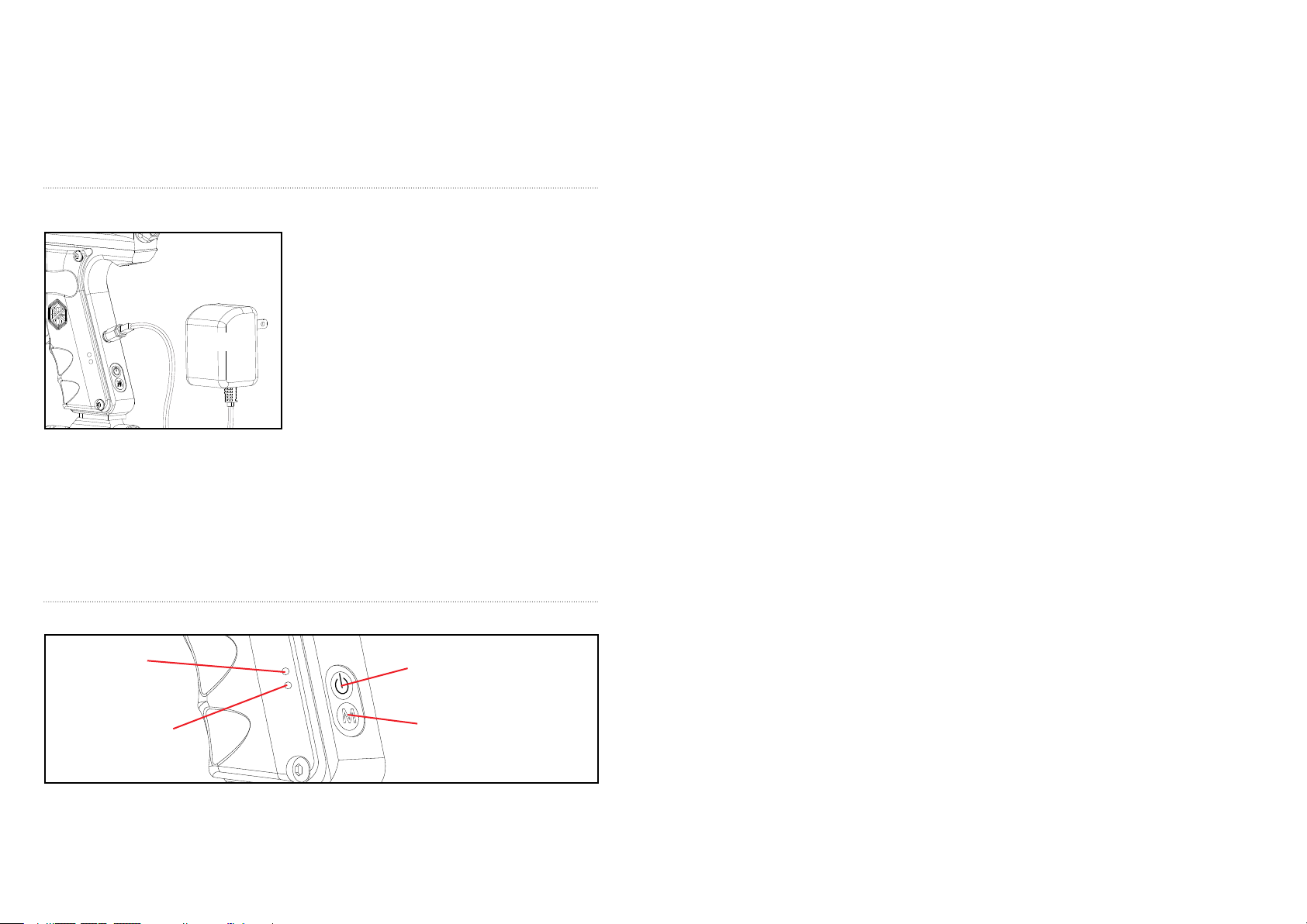
BATT ERY INSTALLATIO N
NOTE: Battery must be fully charged before initial use.
#JE1015
#SCR002
#WRH002
#31202
#SCR002
STEP 1 Remove the three M4x8 Screws (#SCR002) and
left side Grip Panel (#GRP001).
STEP 2 Attach the Spyder Battery (#JE1015) to the
Battery Harness (#WRH002).
STEP 3 Re-tighten the three M4x8 screws (#SCR002).
HELPFUL TIP: Please note how the parts are removed for
easy reassembly.
#GRP001
SPYDER 9.6 NiMH BATTERY LIFE
Always use the supplied Spyder 9.6volt NiMH Battery and Spyder LED A/C Charger to operate this marker. A
fully charged Spyder Battery will last about 3,000 to 5,000 shots. Under normal use and charging conditions the
expected life of the Spyder 9.6 NiMH. Battery to is approximately 700-1,000 charging cycles.
WARNING: This marker is not intended to use any normal 9 volt battery or charger that is NOT a Spyder Product.
Doing so will VOID all electronic warranties and liabilities from Kingman.
3 4
Page 5
WARNING
• Spyder Electronic Markers are not water resistant.
• Extreme moisture can cause serious damage to any Spyder Electronic Marker.
• Always clean any dirt or paint inside the markers electronics.
• Never attempt to modify the electronics circuitry, doing so will VOID all electronic warranties and liabilities
from Kingman.
BATT ERY CHARGING
SPYDER LED A/C CHARGER
IN STRUCTIONS
To charge a Spyder 9.6 NiMH Battery the circuit board must be
in the OFF Position. Spyder Batteries (#JE1015 not pictured)
are not fully charged when purchased. Using the supplied
Spyder LED A/C Charger (#JE1029) Kingman recommends a
#JE1029
STEP 3 The LED indicator on the A/C Charger will display RED when the battery is charging.
STEP 4 The LED indicator on the A/C Charger will display GREEN when the battery is fully charged.
STEP 5 Unplug the Spyder LED A/C Charger cord from the rear of the markers trigger frame.
STEP 6 Remove the Spyder LED A/C Charger from the 110v-120v power outlet.
NOTE: It is recommended that the battery be charged prior to use in order to ensure maximum performance, especially
if the battery has not been used in over a week.
IMPORTANT: You should never charge the battery over 24 hours or you can run the risk of damaging the battery or
electronics.
charging time of 5 hours for a complete charge.
STEP 1 Plug the Spyder LED A/C Charger into a 110v-120v
power outlet.
STEP 2 Connect the Spyder LED A/C Charger cord to the rear
of the markers trigger frame.
EL ECTRONICS & SETTINGS
UPPER
LED LIGHT
LOWER
LED LIGHT
POWER
BUTTON
MODE
BUTTON
CI RCUIT BOAR D SETTINGS AND LED COLOR FUNC TIONS
POWER AND EYE OPERATION:
Press the Power Button to turn marker on. The Tadao Circuit Board will boot instantly, showing a Solid Red LED in
the grip frame. The marker will be in Safe Mode when the marker is rst turned on; to disable the Safe Mode press
and release the Power Button once. When the Safe Mode is disengaged, the LED will switch to Solid Green if the
eyes detect a paintball in the breach, or if the marker is un-cocked. The LED will display a Blinking Green light if
there is no paintball in the breach and the marker is cocked. To disable the eyes, press and hold the Mode Button for
one second. The LED will switch to Blinking Red to indicate that the eye system is disabled. To turn the marker off,
press and hold the Power Button until the LED will turns off when the board powers down.
To determine if the eyes are working correctly, insert an inanimate into the breach and observe whether or not the
LED changes from Blinking Green to Solid Green, and back to Blinking Green once the object is removed.
LED DISPLAY: MEANING:
Solid Red Safe Mode
Blinking Red Eyes disabled (Rate of re capped at 10bps)
Solid Green Ball in Breach, ready to re
Blinking Green No ball in breach
Blinking Yellow Eye malfunction (Remove loader and check breach)
Solid Purple Firing Mode Menu
Solid Teal Blue Trigger Debounce Menu
PROGRAMMING:
Programming Mode can only be initiated while the Tournament Lock is disabled. Pressing the push button switch
to the right of the microcontroller on the Circuit Board will toggle the Tournament Lock. After every press of
the Tournament Lock button while the marker is off, the light will Flash Green or Red to indicate the status of
the Tournament Lock. Green means the Tournament Lock is disengaged, thus allowing the user to enter the
Programming Mode. Red indicates the Tournament Lock is engaged and programming can not be initiated.
TO ENTER FIRING MODE PROGRAMMING MENU:
While the marker is off, press and hold the Mode Button, then press the Power Button and the LED will cycle
through multiple colors until the LED displays Solid Purple for the Firing Mode Setting Menu.
TO CHANGE THE FIRING MODE:
Press and hold the Mode Button until the Solid Purple LED goes out. The LED will blink to show the current Firing
Mode setting. For example, if the current Firing Mode setting is on PSP Ramp, the LED will blink (3) times. Once the
LED stops blinking, you will have two (2) seconds to enter a new mode setting.
To enter a new Firing Mode setting, press the Mode Button to select the new Firing Mode setting. For example, for
Semi-auto Uncapped Mode, you must press the Mode Button once. After the Firing Mode has been selected, turn
the marker off by pressing the Power Button.
Solid Purple Firing Mode
1 Blink (Semi-auto uncapped)
2 Blinks (Semi-auto capped at 15bps)
3 Blinks (PSP Ramp capped at 15bps)
4 Blinks (Millennium Ramp capped at 15bps)
5 Blinks (3 shot burst capped at 15bps)
TO ENTER DEBOUNCE PROGRAMMING MENU:
While the marker is off, press and hold the Mode Button, then press the Power Button and the LED will cycle
through multiple colors until the LED displays Solid Purple for Firing Mode Setting Menu. Press the Mode button
once more and the LED will change to Solid Teal Blue for the Debounce Setting Menu.
TO CHANGE THE TRIGGER DEBOUNCE SETTING:
Press and hold the Mode Button until the Solid Teal Blue LED goes out. The LED will blink to show the current
Trigger Debounce setting. For example, if the current Debounce setting is on Level Three (3), the LED will blink
three (3) times. Once the LED stops blinking, you will have two (2) seconds to enter a new setting.
5 6
Page 6
To enter a new Trigger Debounce Setting, press the Mode Button to select the new Trigger Debounce Setting.
For example, to set the Trigger Debounce to the least sensitive setting, a Level Five (5), you must press the Mode
Button ve (5) times. After the Trigger Debounce setting has been selected, turn the marker off by pressing and
holding the Power Button.
Solid Teal Blue Trigger Debounce
1 Blink (1 ms, cpf 1, amb 1)
2 Blinks (5 ms, cpf 5, amb 2)
3 Blinks (10 ms, cpf 5, amb 3)
4 Blinks (15 ms, cpf 5, amb 4)
5 Blinks (20 ms, cpf 5, amb 5)
(ms – millisecond cpf – cycle percentage lter amb – anti-mechanical bounce)
CAUTION: A “low” Trigger Debounce setting, such as Level One (1) may cause the marker to read trigger switch
bounce as additional trigger pulls, falsely generating shots or near full-automatic re.
SEMI-AUTO MODE LOCK:
To lock the marker in Semi-Auto Mode, a small Circuit Jumper needs to be removed Circuit Board. Removal of this
“Jumper” will lock the Firing Mode in Semi-Auto. The Trigger Debounce setting will still be accessible but all of the
other Firing Modes will be disabled. To re-enable access to all Firing Modes, simply place the Circuit Jumper back
onto the Circuit Board. NOTE: The Trigger Debounce setting is still accessible after the Firing Mode has been locked
in Semi-Auto operation by removing the Circuit Jumper.
ADDITIONAL FEATURES:
Forced Shot – If the eyes are enabled and the breach is empty, but you want to re a clearing shot, a forced shot
can be initiated by pulling and holding the trigger for ½ second. This is useful when you have emptied all your
paintballs from the marker and would like to un-cock or discharge the remaining air inside the marker.
Battery Power Indicator – If battery power is sufcient when the marker powers on, the LED indicator will Flash
Green rapidly. If the battery power is low the LED will Flash Red rapidly, indicating that the battery will need to be
charged.
Sleep Mode – After fteen (15) minutes of inactivity, the Circuit Board will automatically power down, thus saving
battery power.
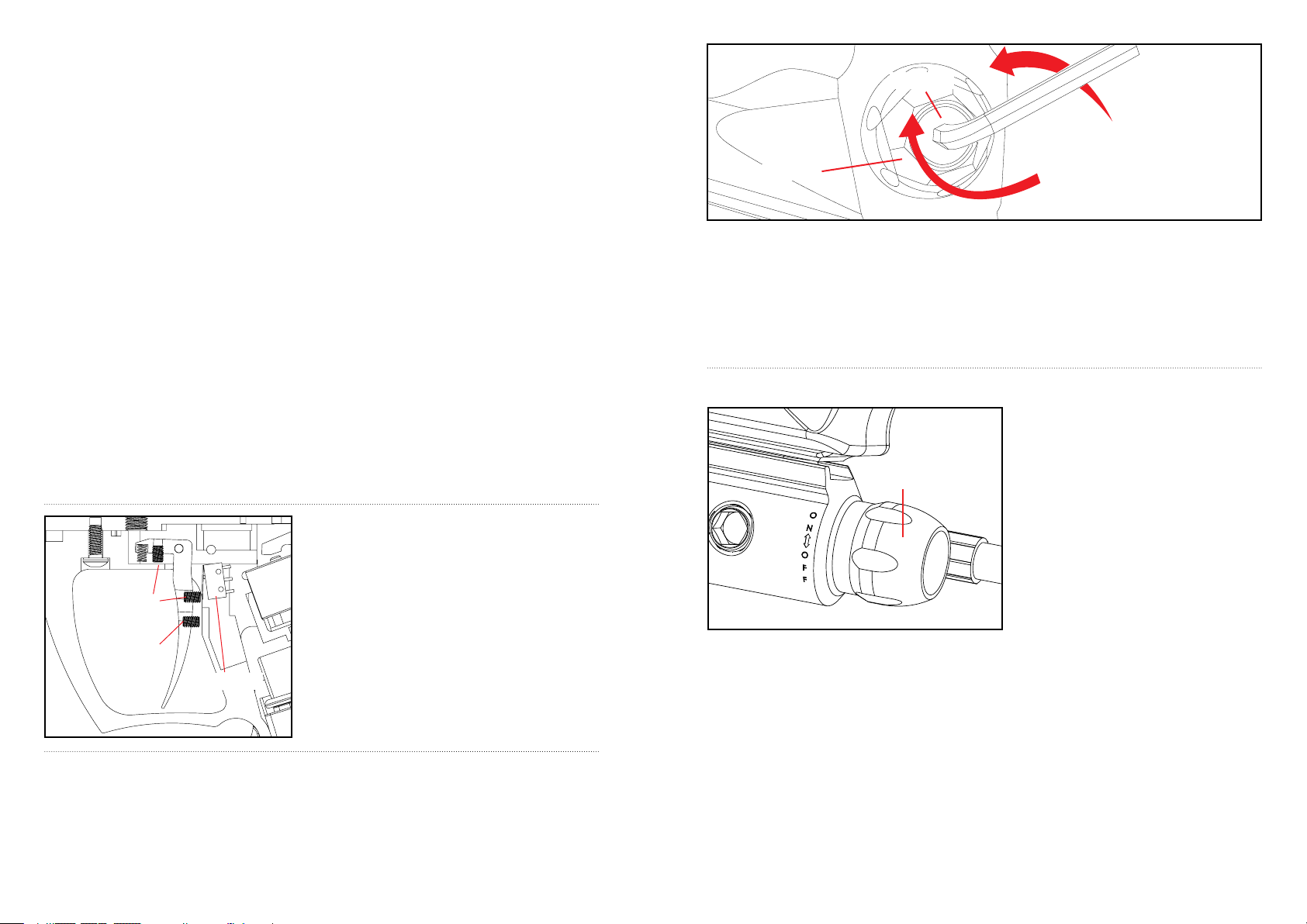
TR IGGER ADJUSTMENT
Adjusting the Top Screw (#SCR006) located underneath the
Trigger Frame clockwise will swing the trigger closer to the
touch switch. NOTE: Adjusting the screw counter-clockwise
#SCR006
#SCR005
#WRH004
will increase the trigger gap. HELPFUL HINT: Over adjusting
the screw to close won’t allow the trigger to activate the touch
switch which will not allow the marker to re.
Adjusting the Middle Screw (#SCR006) clockwise will shorten
the trigger stop the touch switch.
NOTE: This will increase trigger sensitivity. Unscrewing it
counter clockwise will decrease trigger sensitivity.
Adjusting the Lower Screw (#SCR005) clockwise will shorten
the distance on trigger pull.
VE LOCITY ADJ USTMENT INCRE ASE / DECREASE
To INCREASE your velocity FPS (Feet Per Second) using the Allen wrench turn the Velocity Adjuster / Spring
Guide (#VTA021) clockwise.
To DECREASE your velocity FPS (Feet Per Second) using the Allen wrench turn the Velocity Adjuster / Spring
Guide (#VTA021) counter-clockwise.
NOTE: Velocity Adjuster / Spring Guide (#VTA021) doesn’t remove from the rear of the Sticker Plug (#STP021).
RECOMMENDED: To guarantee proper adjustment Kingman recommends using a chronograph to ensure the
markers velocity is under 300fps.
#VTA021
Decrease Velocity
#STP021
Increase Velocity
WARNING
• The recommended Velocity speed should be no greater then 300 fps. Not doing so can cause serious injury if
the Velocity is dangerously high.
• Paintball markers are not intended to shoot any person less then 25 feet.
• Never point a loaded marker at any person who is not wearing the proper face protection.
• Never at any point should you look down the barrel, whether the marker is loaded or not.
• Using a paintball marker outside a non designated paintball eld can be illegal, and is subject to law enforcement
penalties if property damage is caused by the user.
C/A ON/O FF ADA PTER
HELPFUL TIP: Make sure to have the Compressed
Air Tank lled before use.
• Attach your Compressed Air Tank to the C/A
On/Off adapter.
#ASA017
IMPORTANT: Markers that are equipped with regulators may store residual air after the Compressed Air Tank has
been removed. To fully remove any residual air stored in the marker, turn the C/A On/Off adapter knob (#ASA017)
counter-clockwise to shut off the air supplied from the tank. Take several dry re shots with the marker pointed in a
safe direction until the Gauge (#GAG002 not pictured) reads “0psi” and the marker should decock.
IMPORTANT: You should never need to use any hand tool to attach a Compressed Air Tank to the C/A On/Off
adapter.
NOTE: O-rings in the markers parts kit are not supplied to attach with a Compressed Air Tank.
NOTE: The hose line adapter supplied on the C/A On/Off is American thread 1/8” (NPT).
• Tighten the tank clockwise in the markers C/A
On/Off adapter until it is snug. If an air leak occurs
between the tank and the C/A On/Off adapter,
replace the urethane o-ring.
• To pressurize the marker turn the adapter knob
towards the ON position to pierce the pin valve on
the tank.
• To release the pressure turn the dial knob towards
the OFF position. This will release the pressure in
the hose line.
87
Page 7
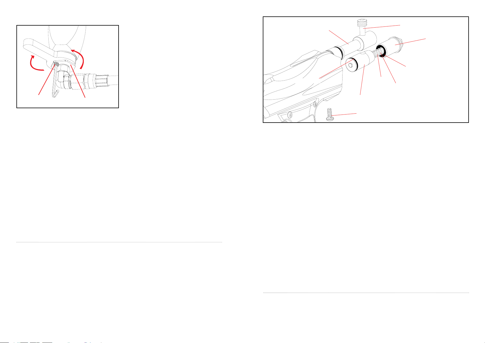
REGULATO R ADJUSTMENT
WARNING: Never at any time should you attempt
to unscrew the Vertical Regulator while the marker is
pressurized. Doing so can cause serious injury or death.
The RSX is equipped with a Vertical Inline Regulator
located in front of the markers trigger frame. Once a
Increase
Velocity
Decrease
Velocity
#SCR026
NOTE: After any adjustment has been made to the Reg Adjuster the Reg Adjuster Lock Screw (#SCR026) must be
re-tightened to prevent any accidental increasing or decreasing of air pressure. TECH TIP: If the regulator output
pressure is less than “200psi”, the marker may experience some re-cocking issues. To achieve the desired pressure
setting, slowly turn the Reg Adjuster Counter Clockwise in small increments and watch the Gauge (#GAG002 not
pictured) while making the adjustment.
When adjusting the Regulator to “Decrease” the output pressure, you will need to re the marker a few times to
get the new setting to “READ” on the gauge. IMPORTANT: (Make sure you have your marker pointed in a safe
direction and you are following all safety guidelines set with the use of this product.) NOTE: Any adjustments made
to the Regulator Adjuster Screw after the marker has been chronographed will alter the marker’s velocity (fps).
HELPFUL TIP: When adjusting the regulator output pressure, always watch the Gauge (not pictured) to insure
the right pressure setting. It’s a good practice to re the marker a few shots every time an adjustment is made to
the regulator, this will allow the regulator to “settle in” to its new output pressure setting. IMPORTANT: Markers
that are equipped with regulators may store residual air after the Compressed Air Tank has been removed. To fully
remove any residual air stored in the marker, turn the C/A On/Off adapter knob (#ASA017) counter-clockwise to
shut off the air supplied from the tank. Take several dry re shots with the marker pointed in a safe direction until
the Gauge (#GAG002 not pictured) reads “0psi” and the marker should decock. IMPORTANT: Do not attempt to
service the regulator unless you have received proper training from a qualied Kingman Group service technician.
Doing so will VOID all regulator warranties and liabilities from Kingman Group. If you experience any leaks or
problem with the regulator, contact Kingman Group Technical Support Service Department. IMPORTANT: Always
remove all paintballs and Compressed Air Tank from your marker and remember to keep the marker in its un-cocked
position before placing it in storage.
#REG006
Compressed Air tank has been installed and tank valve
is opened by turning the C/A On/Off adapter knob
clockwise, the marker is potentially capable and ready to
re.
To INCREASE the regulator pressure, turn the Reg
Adjuster (#REG006) Counter Clockwise with the
regulator wrench.
To DECREASE the regulator pressure, turn the Reg
Adjuster Clockwise with the regulator wrench.
DI SASSEMBLE / REASSEMBLE AND CLEANING OF REAR INTERNALS
Top Cock ing Pin ( #STK00 1)
Delri n Bold (#V BT00 1)
Striker Bolt (#STB 001)
Striker Plug (#STP 021)
Striker O-Ri ng ( #ORG00 1)
Striker Spri ng (#S PR00 1)
Striker Buff er ( #STF00 1)
Trigger Frame Screw ( #SCR00 1)
Velo city Adj uste r & Sp ring Guide (#V TA021)
Saber Trigger (#T RS00 5)
QU ICK CLEAN DISASSEMBLE
Lift upward on the Top Cocking Knob. This will allow the Delrin Bolt to slide from the rear of the Receiver.
HELPFUL TIP: Removing the Delrin Bolt from the Receiver will allow easy access to clean with a squeegee.
NOTE: Make sure the hole on the Striker Bolt is facing upright when looking thru the Receiver. This will allow the
Top Cocking Knob to correctly fasten with the Striker Bolt.
IMPORTANT: The air passage hole located in the middle of the Delrin Bolt should always be facing downward when
reinstalling. If the Delrin Bolt is not installed correctly, paintballs will not exit out of the barrel normally.
#VBT001
#STK001
#STP021
#STF001
#ORG001
#SPR001
#VTA021
#STB001
#SCR001
DI SASSEMBLE REAR INTERNALS
STEP 1 Lift upward on the Top Cocking Knob to allow the Delrin Bolt to slide out from the rear of the Receiver.
STEP 2 Loosen the rear Trigger Frame Screw located underneath the rear Receiver. This will allow all internal parts
such as the Striker Plug with the Velocity Adjuster & Spring Guide Striker Spring, Striker Buffer and Striker Bolt
to slide from the rear of the Receiver. NOTE: Remove the rear Trigger Frame Screw when the marker is in the uncocked position. This way, the tension of the Striker Spring will not allow the markers internals to spring out.
HELPFUL TIP: Placing your nger behind the Striker Plug before removing the rear Trigger Frame Screw will
prevent the markers internals from springing out.
STEP 3 Remove items in order; Striker Plug w/Velocity Adjuster, Striker Spring and Striker Buffer.
STEP 4 Slide the Striker Bolt out of the rear of the Receiver. HELPFUL TIP: When the internals are removed it
would be wise to clean any dirt or paint from the inside of the Receiver with a squeegee. Wipe clean the Delrin Bolt
with a rag or paper towel. Apply some paintball gun oil on Striker O-ring periodically.
RE ASSEMBLE REAR INTERNALS
STEP 1 Reinsert the Striker Bolt with Striker O-ring facing toward the front of the marker with the at spot of the
Striker Bolt facing down. NOTE: Having the Power Switch ON will ease reentry of the Striker Bolt. Apply thumb
pressure behind the Bolt and at the same time pull on the Trigger. Repeat this process until the Bolt is fully inserted.
NOTE: The hole on the Striker Bolt should be facing upright when looking thru the Receiver.
STEP 2 Insert the Striker Buffer ush with the Receiver and place the Striker Spring thru the Striker Buffer.
STEP 3 Place the Striker Plug w / Velocity Adjuster & Spring Guide to the rear of the Receiver and tighten the
Trigger Frame Screw.
STEP 4 Insert the Delrin Bolt thru the rear of the Receiver with the Top Cocking Knob. Press downward on the
Top Cocking Knob to gain entry with the Striker Bolt. NOTE: If the Striker Bolt hole is not aligned upright, the Top
Cocking Knob will not fasten correctly. HELPFUL TIP: Use a small tool to align the hole upright should the Striker
Bolt turn when positioned back in the receiver. WARNING: Before / after use of the marker, make sure to fasten all
screws. Screws may become loose due to vibration. Loose screws can be dangerous and cause injury.
To assure that the marker is assembled properly, follow the schematic drawing or position parts in order during
disassembly. Parts assembled backwards or improper parts installed will / can cause the marker to malfunction.
A JAMMED PAINTBALL IN THE BREACH
In the event of a paintball break and the Delrin bolt jams, follow these steps to help un-jam the marker. The markers
breach is located where the barrel starts to thread in the receiver and underneath the markers feed neck. Before
attempting to un-jam the Delrin bolt you should always have your Goggles or Safety Glasses on. Make sure the
marker is in the SAFE / OFF position before attempting to un-jam the Delrin bolt. Remove the Compressed Air Tank
109
Page 8
before attempting to un-jam the marker. Remove all paintballs and the loader from the feed neck. Have the barrel
removed from the receiver to allow the paintball(s) to exit. With enough force tension on the Cocking Knob, pull
back to release the Delrin bolt from the jammed position. Another method is to use a “Straight Shot Squeegee” or
the end of a wood dowel rod; push against the face of the Delrin bolt with enough force to release the jammed bolt.
Always clean the paint from the breach and barrel to enhance the performance of your marker. IMPORTANT: Never
look down the barrel of the marker when loaded or unloaded. Remove the attached Compressed Air Tank before
attempting to un-jam the Delrin Bolt. NOTE: Never use a metal rod or screwdriver as a tool to push on the Delrin
bolt, anything metal will scratch and damage the inside of the marker.
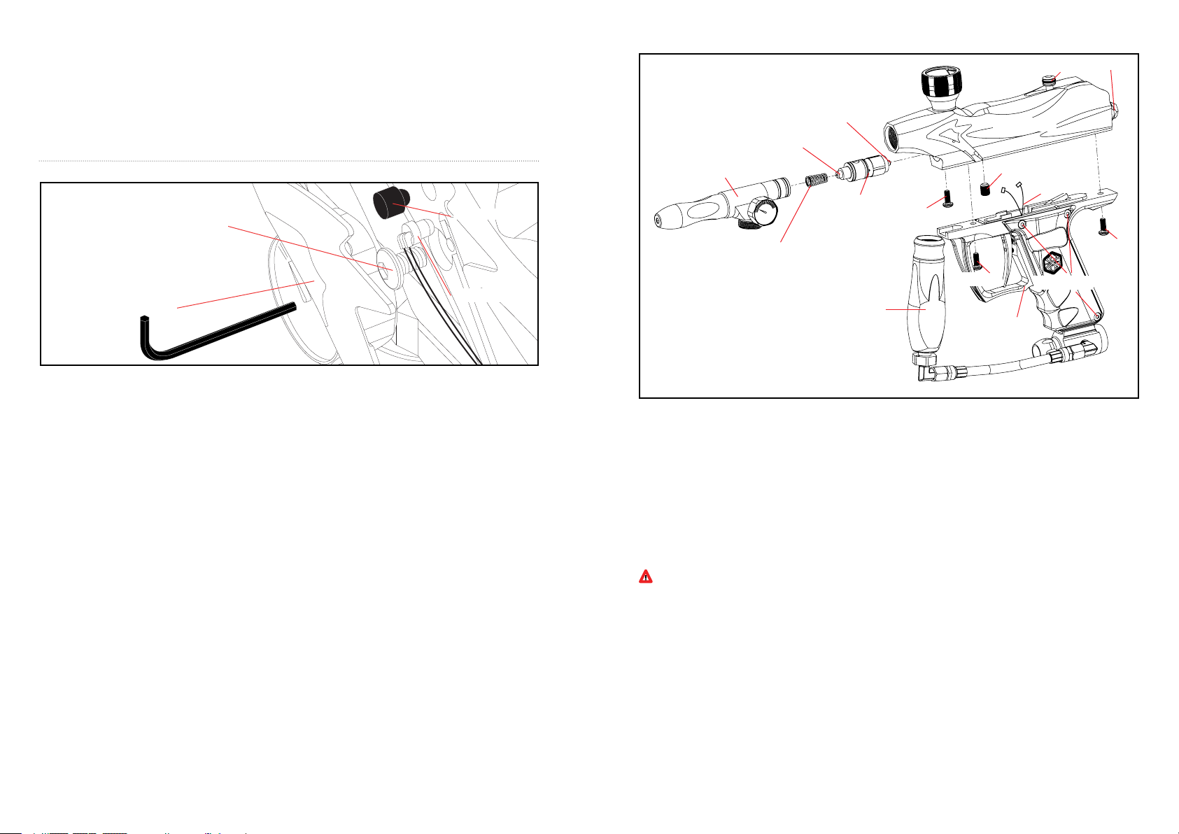
ANTI CHOP EYES
#SCR004
#BLS002
CU P SEAL REMOVAL
#ITP001
#VRT001
#SPR002
#ITP002
#ITP003
#STK001 #STP021
#REC021
#SCR007
#WRH006
#SCR008
#SCR001
#BLS021
#WRH006
The Anti Chop Eyes help prevent the chopping of paint by not allowing the marker to re until a paintball is properly
chambered in the breach. The Eyes transmit a beam across the inside of the breech. The circuit board is preset from
the factory and does not need to be adjusted or altered. (If the Eyes are ON and do not see each other when ring
your marker, you will have to clean the Eyes.)
CL EANING THE ANTI CHOP EYES
Using a squeegee or swab thru the breech should clean the Eyes enough for the Eyes to detect each other. Another
way is to use an aerosol can of air thru the breech to remove any paint or dirt. To thoroughly clean the Eyes using
the supplied Allen wrench remove both Eye Panel Screws (#SCR004) and Eye Panels (#BLS021). Once the Eye
Panel Screws & Eye Panels are removed, proceed with a soft pinch to remove the Eye Wire Harness (#WRH006)
from the receiver. Use a cloth or paper towel to remove any paint or dirt that is blocking the Eyes.
IMPORTANT: Cleaning the Eyes often will help reduce dirt, paint or oil residue that blocks the Eyes.
NOTE: Never attempt to rush the cleaning process or you can pinch the wires and cause the marker to malfunction
with the Eye Mode ON. Take precaution not to over tighten the Eye Panel Screws or this can lead to stripping
the head. NOTE: When the Eye Panels are removed the Ball Stopper(s) (#BLS002) may be attached to the Eye
Panels and can cause them to fall out. HELPFUL TIP: Please note how the parts are removed for easy reassembly.
IMPORTANT: Before removing both Eye Panels use a needle or dental pick thru the hole of the Eye Panel to
remove any dirt that can build up and block the Allen screw from loosing. It’s possible if the dirt is not removed you
can strip the Eye Panel Screw.
CH ANGING THE BALL STOP PERS
Experiencing paint rolling through the barrel can be related to small diameter paintball(s) or the loss of a Ball
Stopper(s) (#BLS002). When removing Eye Panel Screws (#SCR004) and Eye Panels (#BLS021) the Ball
Stopper(s) will be accessible for cleaning or replacement. HELPFUL TIP: Please note how the parts are removed
for easy reassembly. IMPORTANT: Before removing both Eye Panels use a needle or dental pick thru the hole of
the Eye Panel to remove any dirt that can build up and block the Allen screw from loosing. It’s possible if the dirt is
not removed you can stripe the Eye Panel Screw. NOTE: Take precaution not to over tighten the Eye Panel Screws
or this can strip the head.
#SCR001
#SCR002
#REG001
#TRF002
Part Name s an d Pa rt Num bers des cribe in t his se lect ion:
Cup S eal (#IT P001) Trig ger Frame Screw (# SCR001)
Valv e Sp ring (#SPR 002) M4 x8 H ead Scre w (# SCR0 02)
Inlin e Re gula tor (#REG0 01) Rec eive r (# REC021)
Trigger Frame (#TR F002 ) Val ve B ody (#ITP0 03)
Vert ical Screw (# SCR008) * 9.6 Recharg eabl e Ba ttery (#JE 1015 )
Eye Wire Ha rnes s (#WR H006) * Veloci ty A djus ter & Spri ng G uide ( #VTA021)
Valv e Bo dy S crew (#SCR 007) *De lrin B olt (#VB T001)
Striker Plug (#STP 021) *Stri ker Spri ng (#S PR00 1)
Top Cock ing Kn ob ( #STK00 1) *Stri ker Bol t Mi ni (#S TB00 1)
Valv e Pi n (# ITP0 02) *S triker Buff er ( #STF00 1)
Vert ical Ada pter w/Gaug e (# VRT001) *pa rts not sh own
ST EP BY STE P
WARNIN G: N ever at any time shou ld y ou att empt to un screw t he Vertica l Regul ator w hile the
marker i s pressur ized . Doin g so can cause ser ious i njur y or dea th.
HELPF UL TIP : Th e si gn of a wo rn Cup Se al i s the presenc e of Com pres sed Air leaki ng dow n th e barre l.
STEP 1 Twist t he Inline Reg ulator cou nter-cl ockwis e to rel ease off the Ver tical Adapter w/Gaug e. The
hose line w ill hold the Inli ne Regula tor wh en i t da ngles from th e C/A On /Off.
STEP 2 Remove all t hree M4x 8 Sc rews on th e le ft s ide of the Trigger Fram e. T he G rip Pane ls wil l al low
access t o the Circ uit Boar d.
STEP 3 Gent ly d etach the Eye Wire Harne ss from t he C ircu it B oard . Th is wil l al low ma neuveri ng around
certa in p arts. HELP FUL TIP: G entl y mo ve asid e the Rech argeabl e Ba ttery out of the Trigg er Frame t o
view the Eye Wire Har ness . Ge ntly rem ove the Eye Wire H arne ss thr u th e co il s et cha nnel exi ting thru
the t op of the Tr igge r Frame.
STEP 4 Remove bot h Trigge r Fra me Screws . Th is wil l th en all ow t he Tri gger Frame t o di scon nect from
the R ecei ver. P ull up ward on the Top Cocki ng K nob to all ow the Del rin Bolt t o re leas e from the Stri ker
Bolt Mini . Once th e St rike r Pl ug h as bee n re moved t he S triker Spring , Strik er B uffe r an d St rike r Bo lt
Mini need to be removed o ut the rear o f th e Re ceiv er.
1211
Page 9
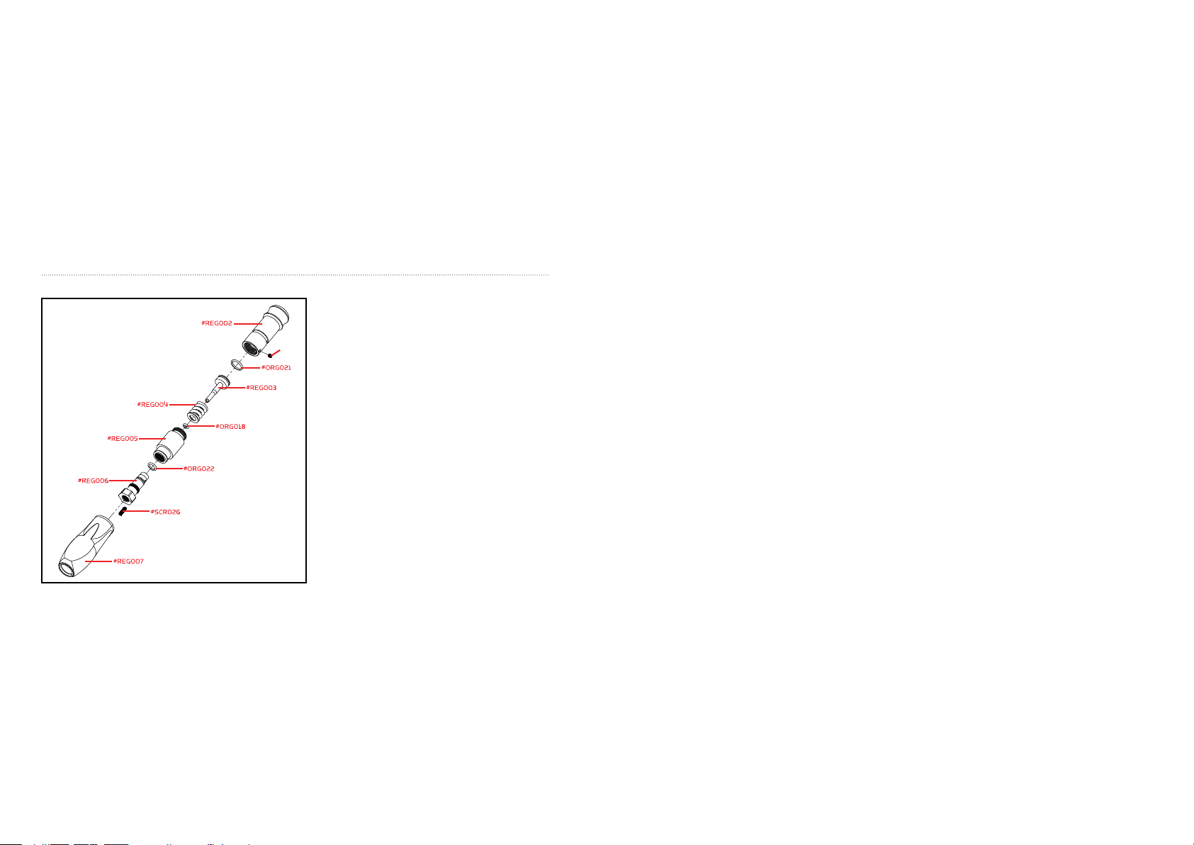
TECH TIP: Before loosening the rear Trigger Frame Screw place your nger in front of the Striker Plug, so the internal
parts don’t spring outward if the Delrin Bolt is in the cocked position.
TECH TIP: Notice how the Striker Bolt Mini is placed in the Receiver before removed to ease re-entry.
STEP 5 Loosen the Vertical Screw counter-clockwise to allow the Vertical Adapter w/Gage to release from the
Receiver.
STEP 6 Loosen the Valve Body Screw counter-clockwise to allow access to the Valve Body.
STEP 7 Use a plastic or wooden dowel rod to push the Valve Body from the rear of the Receiver thru the front of the
Receiver. TECH TIP: Use an 8” or longer rod thru the lower rear section of the Receiver. Notice how the Valve Body is
placed inside the Receiver before removing. This will help ease re-entry after installing the new Cup Seal.
STEP 8 Untwist both half’s of the Valve Body to gain access of the Valve Pin.
STEP 9 Untwist the Cup Seal from the Valve Pin. Replace the defective Cup Seal.
HELPFUL TIP: Please note how the parts are removed for easy reassembly. CAUTION: Use the proper Allen
wrenches to fasten all screws and never apply more force than necessary. IMPORTANT: Always
remove the Air Tank before any disassembly of your marker. Do not remove the Valve Body (#ITP003) unless specic
Valve Body repairs are needed. Do not remove the Valve Body with a screwdriver as it will damage the Valve Body
and cause air leaks.
REGULATO R MAINTENANCE / SCHEMATIC S
WARNING: Never at any time should you attempt to
unscrew the Vertical Regulator while the marker is
pressurized. Doing so can cause serious injury or death.
#SCR025
IMPORTANT: Markers that are equipped with
regulators may store residual air after the Compressed
Air Tank has been removed. To fully remove any
residual air stored in the marker, turn the C/A On/Off
adapter knob (#ASA017 not pictured) counterclockwise to shut off the air supplied from the tank.
Take several dry re shots with the marker pointed in a
safe direction until the Gauge (#GAG002 not pictured)
reads “0psi” and the marker should decock.
Apply a small amount of grease on part numbers; Reg
Piston O-ring (#ORG021) and Reg Adjuster O-ring
(#ORG022).
Having the Regulator in its optimal performance,
you should maintain a clean and dirt free regulator.
Depending on the usage of your marker, it’s a good idea
to practice cleaning inside regulators internals.
TECH TIP: Using, grease like (Dow Corning ® 33 medium consistency) or any paintball grease on the following parts
listed will maintain the functioning of your Regulator.
HELPFUL TIP: Please note how the parts are removed for easy reassembly.
TROUBLESHOOTING
ONE OR MORE OF THE FOLLOWING MAY CAUSE RECOCKING RELATED ISSUES:
• The pressure in the tank is too low and possibly needs to be relled.
• Need lubrication on the following Striker O-ring (#ORG001) might be damaged or missing. Replace with a new
Kingman approved Striker O-ring (see Disassemble / Reassemble). NOTE: The Striker O-ring can not be substituted
with a black or urethane bottle o-ring.
• Dirt or broken paint shell fragments inside the receiver can cause the marker to have recocking issues. Using a
squeegee through the upper portion of the receiver will remove most of the dirt or broken shell fragments. Should
this issue continue, (see Disassemble / Reassemble) remove the markers internals for complete cleaning. Using
low quality paintballs can cause the marker to experience recocking issues because of the shape of the paintballs.
HELPFUL TIP: Paintballs have a shelf life and can become too fragile for use.
HELPFUL TIP: Paintballs can take a different shape over time, so it would be wise to size the paintball with
your barrel.
ELECTRONIC GRIP TROUBLESHOOTING
If your marker is not shooting it may be due to one of the following problems:
• Battery may need to be recharged.
• The Battery Wire Harness is not properly attached to the circuit board.
• The Coil Set Harness is not properly attached to the circuit board.
• The Touch Switch Harness is not properly attached to the circuit board.
NOTE: If the Markers Electronics have any dirt or paint, Kingman recommends using an aerosol can of air. Apply
the can of air directly at the components that need cleaning.
AIR LEAKS
IMPORTANT: Always remove the air tank before any disassembling of the marker.
• Air leaking from the Lower Pressure Chamber means the O-ring (#ORG002) will need to be oiled or replaced.
• Air leaking from the Vertical Adapter means the O-ring (#ORG002) will need to be oiled or replaced.
• Air leaking down the barrel is usually a Cup Seal (#ITP001) that is worn or damaged (see Cup Seal Removal).
The Cup Seal should the exchanged.
• Never remove Valve Body (#ITP003) unless specic repairs are needed.
• A nick or scratch on the lip of the Valve Body can cause an internal air leak (see Cup seal Removal). The Valve
Body may need to be replaced.
• Air leaking thru the Receiver and out of the Trigger Frame would indicate the Valve Body O-rings (#ORG002)
will need to be replaced.
• If air is leaking thru the opposite end of the hose ttings, please check the following: The Female end of the
Hose must have a plastic washer (#HSF004) installed inside the hose collar and be tightened properly.
HELPFUL TIP: To assure marker is assembled properly, follow the schematic drawing or position parts in order
during disassembly. Parts assembled backwards or improper parts installed will / can cause the marker to
malfunction.
WARRANTY STATEMENT
Kingman warrants the original retail purchaser that this product is free from defects in material and workmanship
under normal use and service for a period of (1) year from the original date of purchase. Any Electronic Components
in an Electronic Spyder marker are warranted for (3) months from the original date of purchase. Kingman agrees
to repair or replace (at its discretion) any product within (a reasonable period of time). This warranty does not
cover o-rings, cup seals, 9.6v rechargeable battery, charger, scratches, nicks, normal wear and tear of parts, any
modications, normal fading of anodizing and damage caused by dropping or hitting of products. This warranty shall
not apply if it is shown by a Kingman Technician that the consumer caused the defect or malfunction because of
misuse. This warranty only covers original factory parts. Any modications or tampering of original factory parts
will VOID warranty and liabilities from Kingman. Any damage caused by water will not be covered under warranty.
Warranty repair can only be conducted by Kingman technician or Kingman authorized technician. For warranty to be
effective, consumer must return the enclosed warranty registration card lled out, along with a copy of the purchase
receipt, within (15) days of the original purchase date. This warranty is not transferable. Paintball markers are
non-refundable. This warranty will not cover pick up, shipping, delivery, and/or house calls. If product needs repair,
consumer will package it carefully and send together with your name, address, phone number and a brief description
of the malfunction to:
KINGMAN GROUP
Attn: Tech Department
14010 Live Oak Avenue
Baldwin Park, CA 91706 U.S.A.
www.kingman.com
VIIK
FOR TECHINICAL SUPPORT
Our Technical Support Department is open Monday through
Friday, from 8am to 5pm (PST), and can be reached at
(626) 430-2300.
www.spyder.tv
1413
Page 10
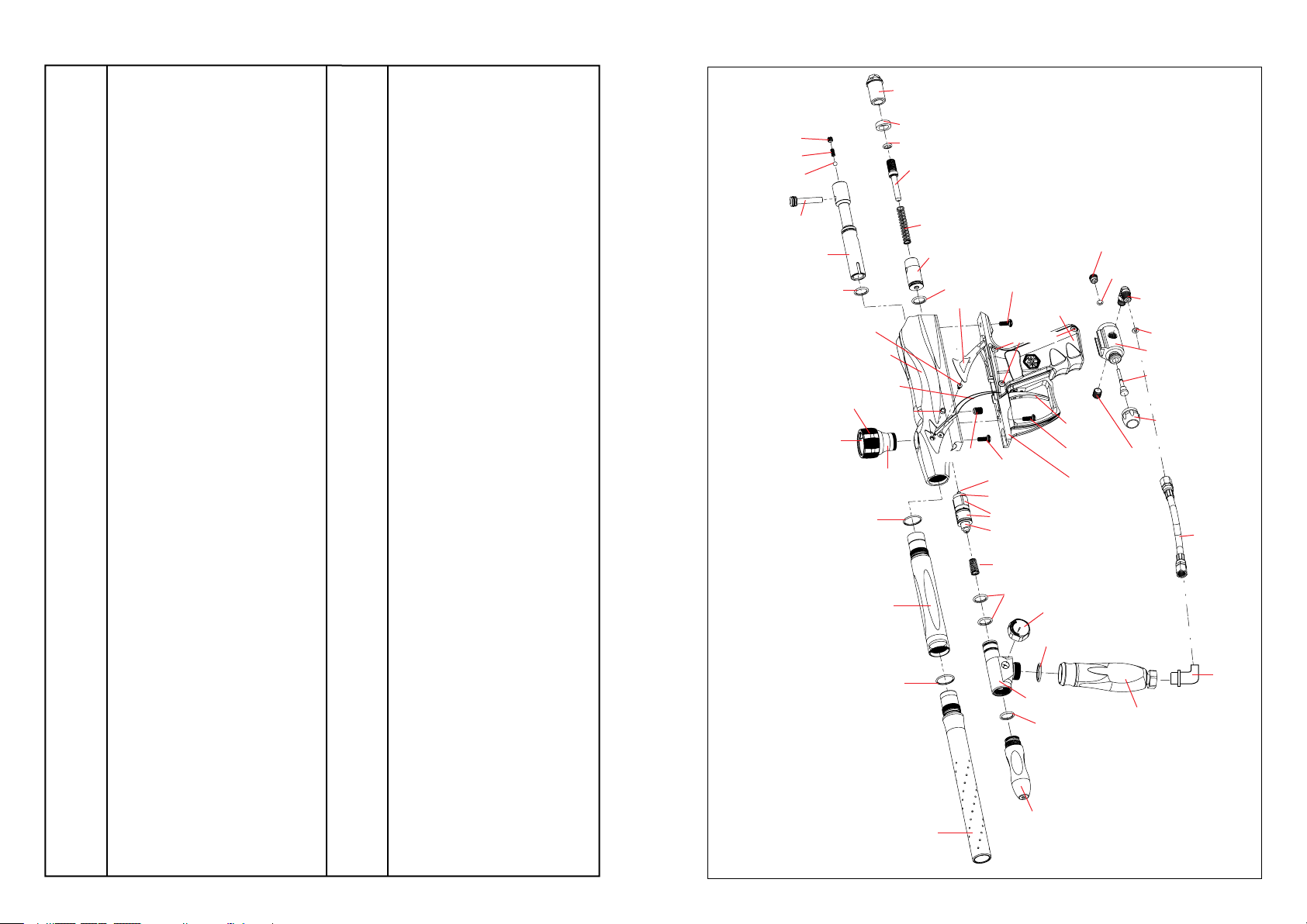
RSX PARTS LIST
AS A012 C/A On/Of f D epre ssin g Pi n
AS A013 C/A On/O ff R etai ning Scr ew ( f)
AS A017 C/A On/Of f Ad apte r Kn ob (matt e b lack )
AS A018 C/A O n/Of f 1/8 Hos e Pl ug
AS A020 C/A On /Off Ada pter (ma tte blac k)
BAR 010 12 ” 2P CS B arre l
BAR 021 1 2” B arre l Ti p (ma tte sil ver)
BL S021 E ye P anel Set (ma tte silv er)
BL S002 Bal l St oppe r
31 202* Tad ao C ircu it B oard
EL M001 * Co il S et
EL M002 * Coi l Pi n
EL M004 * Capa cit or
EL M005 * Touch Swi tch Mem brane
FN D001 Fee d Ne ck
FN D002 Twis t Cl amp C Cl ip I nser t
FN D021 Twi st Clam p C (mat t si lver )
GAG 002 60 0 p si G auge
GR P001 Wrap Aro und Grip (b lack )
GR P002 * LED Len s
HS E008 Di scon nect Hos e (f emal e x fema le)
HS F004 Pl asti c Was her
HS F009 90 d Ma le t o Ma le Adapt er (STD x M ET)
IT P001 C up S eal
IT P002 Val ve P in
IT P003 Va lve B ody
IT P004 Valv e Bo dy B uffe r
JE 1015 * 9. 6v Re cha rgeab le Batt ery
JE 1029 * A/C Cha rger w/ L ED
LP C021 Low Pre ssur e Ch ambe r (m atte sil ver)
OR G001 S trik er O -rin g
OR G002 O- rin g #0 15 8 0D
OR G003 B arrel O- ring
OR G005 Ver tica l O -rin g
OR G006 * I nner Valve Bod y O -rin g
OR G008 #0 10 O -rin g
OR G016 * Val ve Pi n O -rin g (L )
OR G017* Val ve Pi n O- rin g (S )
OR G018 Inn er R eg O -rin g #0 08-70
OR G021 Re g Pi ston O-r ing #014 -7 0
OR G022 Reg Adj uste r O- rin g
PAK0 01* S pare Par ts K it
RE C021 R SX Re ceiv er
RE G001 Re gula tor (com plet e)
RE G002 Re g Top B ody
RE G003 Re g Pi sto n
RE G004 R eg S pri ng
RE G005 Re g Mi d Bo dy
RE G006 Reg Adj uste r
RE G007 Reg Rub ber Grip
RP N001 * Se ar R oll Pin
RP N002 * Trigg er/Touc h Sw itch Rol l Pi n
RP N004 * Tri gger Rol l Pi n
SC R001 Trigg er Frame Scr ew (A )
SC R002 M4 x 8 Scre w w/w ashe r (A)
SC R003 * Ci rcui t Bo ard Scre w (+ )
SC R004 E ye P anel Scr ew (A )
SC R005 * Trig ger Scre w ( S)
SC R006 * Tri gge r Sc rew (L)
SC R007 Val ve B ody Scre w (A )
SC R008 Ve rtic al S crew (A)
SC R010 * Dov e Tail Loc k Sc rew (A)
SC R011 Coi l Se t Sc rew
SC R025 R eg S crew M4 x 4 (45A )
SC R026 Re g Adj ust er Lo ck Screw (2 9B)
SE R001 * Sea r
SP R001 St rike r Sp rin g
SP R002 Val ve S prin g
SP R009 * ES P Se ar S prin g
SP R010 * ESP Tr igg er S prin g
ST B001 Str iker Bol t (m ini)
ST F001 St rike r Bu ffer
ST K001 Top C ocki ng K nob
ST P021 S trike r P lug (mat te s ilve r)
TR F002 Trigg er F rame
TR S005 Sab er Tr igge r (m atte bl ack)
VB T001 Del rin Bolt w/ Lock ing Knob
VB T002 D elr in B olt Lock ing Scre w
VB T003 Del rin Bol t Loc king Bea rin g
VB T004 De lri n Bo lt L ocki ng S prin g
VR T001 Verti cal Adap ter w/ G aug e
VTA0 21 Velo city Adj uste r & Spri ng Guid e (m. sil ver)
WR H002 * Ba tte ry H arne ss
WR H004 * Touc h Sw itc h (3 P)
WR H006 * E ye W ire Harn ess (lon ger wire)
RSX SCHEMATICS
#VBT002
#VBT004
#VBT003
#STK001
#VBT001
#ORG002
#SCR004
#FND021
#FND002
#ORG003
#REC021
#WRH006
#BLS002
#FND001
#BAR010
#ORG003
#STP021
#STF001
#ORG008
#VTA021
#SPR001
#BAR021
#STB001
#ORG001
#BLS021
#SCR007
#SCR001
#GRP001
#SCR002
#SCR008
#ITP002
#ITP004
#ITP003
#ITP001
#SPR002
#ORG002
#VRT001
#LPC021
#TRS005
#SCR001
#TRF002
#GAG002
#ORG005
#ORG002
#ASA013
#ORG018
#HSF009
#HSF004
#ASA020
#ASA012
#ASA017
#ASA018
#HSE008
#HSF009
#REG001
* Item Not Pictured
1615
Page 11

 Loading...