

Page 1
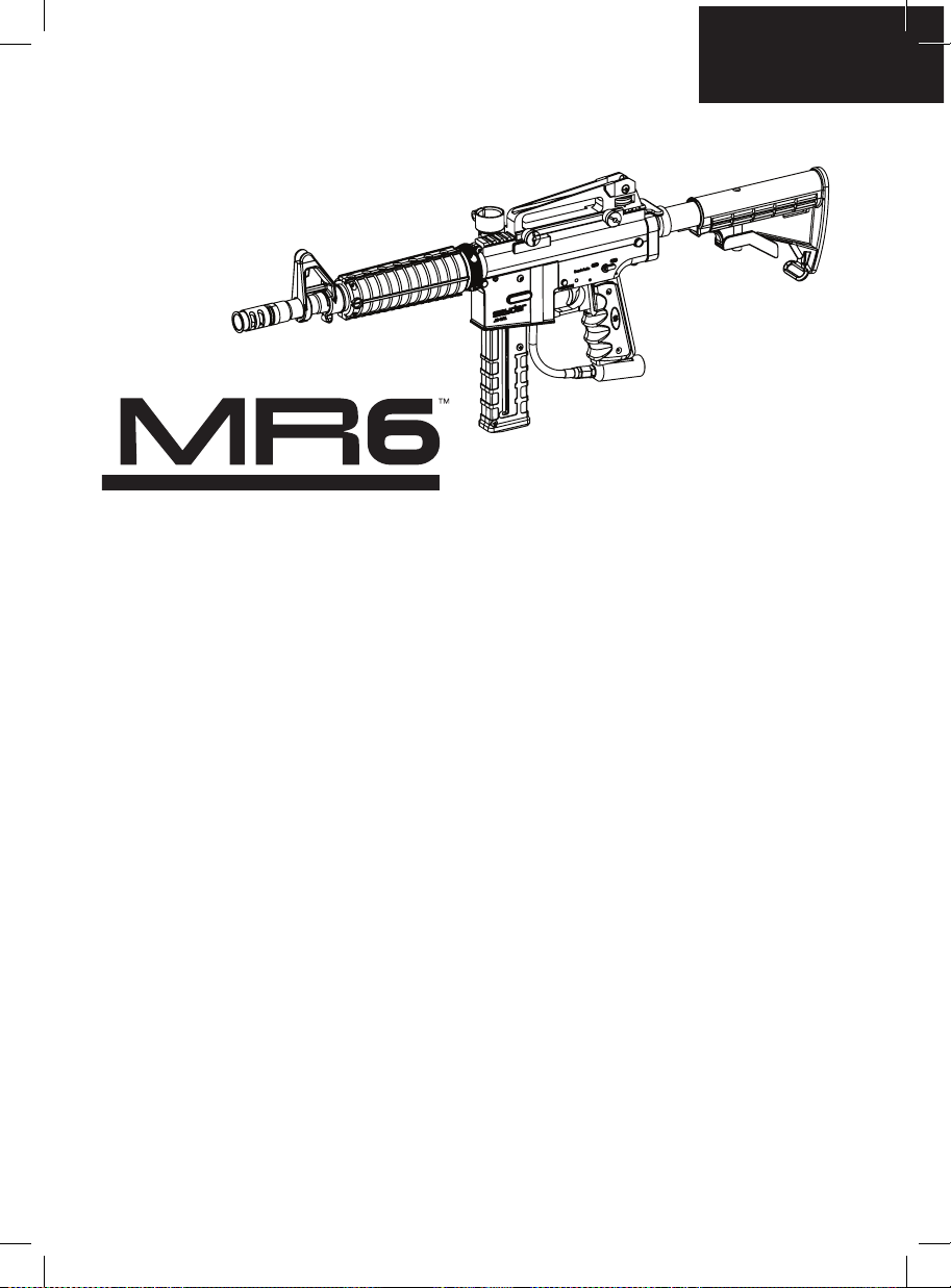
.68 CAL SEMI-AUTO MARKER
Page 2

Page 3
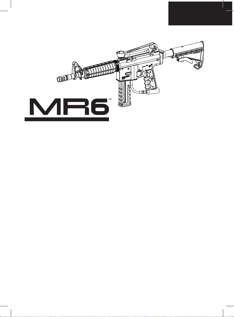
.68 CAL S EMI-AU TO MARKER
TABLE OF CONTENTS
IMPORTANT SAFETY GUIDELINES
OPERATION GUIDE / START UP
MR6™ BARREL INSTALL / REMOVAL / SETUP
PROPER USE OF BARREL BLOCKING DEVICE
INSTALLING / REMOVING CO2 / COMPRESSED AIR TANK
INSTALLING CARRYING HANDLE W/SIGHT
INSTALLING / REMOVING A PAINTBALL LOADER AND MAGAZINE
INSTALLING / REMOVING A SHOULDER STOCK
VELOCITY ADJUSTMENT INCREASE / DECREASE
A JAMMED PAINTBALL IN THE BREACH
HOW TO CLEAN YOUR MARKER
DISASSEMBLE / REASSEMBLE REAR INTERNALS
BARREL SHROUD REMOVAL
Eko™ CUP SEAL REMOVAL GUIDE
AIR LEAK / TROUBLESHOOTING
TROUBLESHOOTING
MR6™ SCHEMATIC
MR6™ PARTS LIST
WARRANTY STATEMENT
English
1
2
3
3
4
4
4-5
6
6
6
7
7-8
8
9
10
10
11
12
13
Page 4
RULES OF SAFE PAINTBALL MARKER HANDLING
1.
Do not use unless everyone within range is wearing eye, face and ear protection designed
specifically to stop paintballs and complies with specification ASTM F1776.
2.
Never point the paintball marker at anyone that is not wearing a paintball mask that complies
with specification ASTM F1776.
3.
Do not modify your marker’s pressurized air system or cylinder in any way.
4.
Keep the marker on safe until ready to shoot.
5.
Never use anything other than .68 caliber paintballs. Do not attempt to shoot used paintballs.
6.
Treat every marker as if it were loaded.
7.
Never look down the barrel of a paintball marker.
8.
Keep your finger off the trigger until ready to shoot.
9.
Never point the marker at anything you don’t wish to shoot
10.
Keep the barrel blocking device in/on the marker’s muzzle when not shooting.
11.
Keep the paintball marker on safe when not in use.
12.
Always remove paintballs and propellant source before disassembly.
13.
After removing propellant source, point marker in safe direction and discharge until marker
is degassed.
14.
Store the marker unloaded and degassed in a secure place.
15.
Follow warning listed on the gas source for handling and storage
16.
Do not shoot at fragile objects such as windows
17.
Always measure your marker’s velocity before playing paintball and never shoot at
velocities in excess of 91.44 m/s (300 ft/s)
18.
Never engage in vandalism.
19.
Some paintballs may cause staining of some porous surfaces such as brick, stucco, and
wood.
WARNING: This is not a toy. Misuse may cause serious injury or death. Eye protection designed
specifically for paintball must be worth by the user and persons within range. Must be 18 years or older to
purchase. Persons under 18 must have Adult supervision. READ OWNER'S MANUAL BEFORE USING.
1
Page 5

English
OPERATION GUIDE /START UP
1. Always attach a barrel blocking device over the tip of the barrel for safety precautions when not shooting/
playing
2. Spyder recommends having the Marker in the SAFE MODE position before use. To operate, push the
safety button from the “PUSH SAFE” side of the Trigger Frame. This will position the Marker in a lock
SAFE MODE. To disengage the safety button in a safely manner, point the Marker in a safe direction, and
push the safety button towards the opposite side of the Trigger Frame. CAUTION: Do not disengage
safety button until step 6.
3. Attach a CO2/Compressed Air Tank to the Markers C/A adapter. Using a CO2/Compressed Air Tank
rmly tighten clockwise to the Markers C/A adapter until it is snug. HELPFUL TIP: Make sure to have the
CO2/ Compressed Air Tank lled before attaching. NOTE: O-rings in the Markers parts kit are NOT
supplied to attach with a CO2/Compressed Air Tank. IMPORTANT: You should never need to use any
hand tool to attach a CO2/ COMPRESSED AIR TANK to the Markers C/A adapter.
4. Attach the Magazine to the Trigger Housing or attach Paintball Loader to the Marker’s clamping feed neck
and tighten the screw. NOTE: The loader can only be lled with .68 Caliber Paintballs. The Magazine can
accept either .68 Caliber Paintballs or First Strike Paintball Rounds
5. Cocking the Marker. Pull back the Rear Cocking Handle until the FS Venturi Bolt latches.
CAUTION: Should you let go of the Rear Cocking Handle before it latches, your Marker may re.
6. Remove the barrel blocking device over the barrel. Now you can release the safety button. CAUTION:
With the safety button released in the FIRE position the Marker is ready to shoot/play. By pulling the
Trigger will re a paintball. IMPORTANT: Only test your Marker in a safe direction or in a designated
playing eld.
7. Performing a velocity (fps) check. Turning the Velocity Adjuster/Spring Guide clockwise will increase the
velocity (fps) while turning counter-clockwise will decrease the velocity (fps). NOTE: Your Marker is
intended to be used in a paintball facility with the proper paintball protection. IMPORTANT: Spyder
recommends using a chronograph to ensure Marker’s velocity is under 300 (fps).
8. When nished playing, remove all paintballs from the Magazine and Loader. Then detach the loader from
the Markers feed neck by loosening the set screw on feed neck clamp. CAUTION: There may be one
paintball in the Marker’s breach; take a shot or two in a safe direction to make sure the barrel and
Receiver are empty.
9. Place the barrel blocking device over the barrel tip. This will help avoid any accidental discharge.
10. Spyder recommends having the Marker in the SAFE MODE and un-cocked position after use.
11. Unscrew the CO2/Compressed Air Tank from the Markers C/A adapter. By turning the tank counter
clockwise will detach from the Markers C/A adapter. CAUTION: Never expose any skin underneath the
C/A adapters bleed hole when removing the tank. This can run the risk of getting skin burn from the
releasing of the GAS. IMPORTANT: You should never need to use any hand tool to detach a CO2/
Compressed Air Tank from the Markers C/A adapter.
12. Store the Marker in a paintball bag or in a safe place. WARNING: Before/after use of the Marker, make
sure to fasten all screws. Loose screws may prevent the Marker from functioning properly. HELPFUL TIP:
It’s a good practice to lubricate your Marker before and after each use, especially when storing the
Marker for an extended period of time. Add a few drops of paintball gun oil on the Striker O-ring (SEE
DISASSEMBLE/REASSEMBLE AND CLEANING OR REAR INTERNALS). Before storing the Marker,
make sure the Marker is in the SAFE MODE, un-cocked position without air source attached, any paintball
inside the Marker has been removed and with barrel blocking device on.
IMPORTANT
• Firing velocity will vary according to altitude, climate condition, and type of paintball used. First Strike
Rounds will have a higher velocity than a regular .68 Caliber paintball.
• It may be dangerous approximately within 300 feet (100 meter) of shooting range.
• Before using your marker in play, you must always rst perform a “SAFE VELOCITY TEST”. This can only
be accomplished by using a testing device called a “Velocity Chronograph“ and can be performed at a
paintball dealership or local playing eld. NOTE: This product is intended to be used at a velocity no
greater than 300 feet per second (fps). Paintball markers are not intended to shoot within 30 feet.
• This paintball marker may have excess gas after the removal of the CO2 / Compressed Air Tank. Please
remove all paintballs and discharge the remaining gas safely.
• Never store a CO2 / Compressed Air Tank attached on the marker.
2
Page 6
MR6 BARREL INSTALL / REMOVE / SETUP
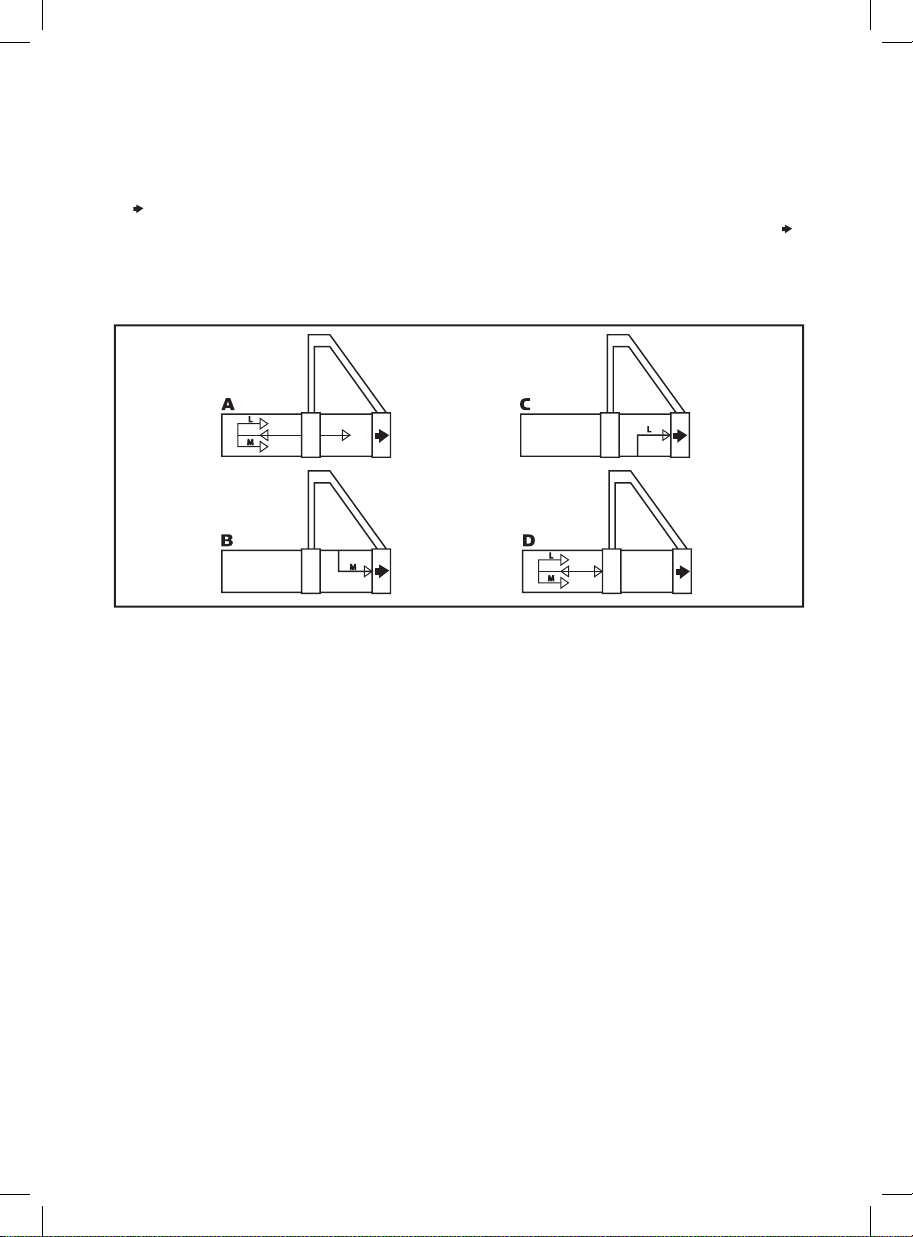
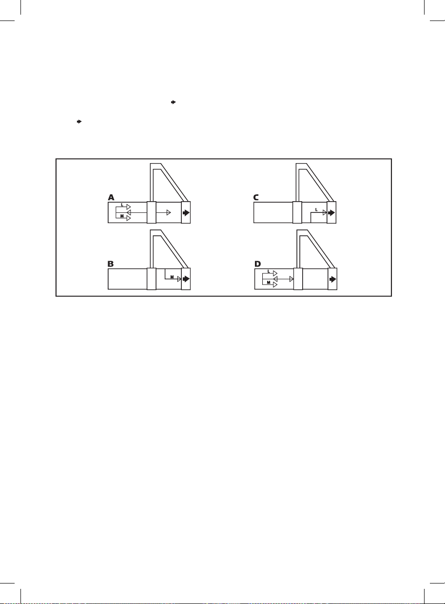
To install the barrel you must lineup the center arrow marked on the barrel to the arrow marked on the shroud
sight (see gure A) once lined up, insert the barrel.
To set up for “Magazine” feeding, turn the barrel counterclockwise making sure the arrow marking on the barrel
(M ) is lined up with the arrow marked on the shroud sight (see gure B).
To set up for the “Loader” feeding, turn the barrel clockwise making sure the arrow marking on the barrel (L )
is lined up with the arrow marked on the shroud sight (see gure C).
Removing the barrel you must lineup the center arrow marked on the barrel to the arrow marked on the shroud
sight (see gure D) once lineup then pull the barrel out.
PROPER USE OF YOUR BARREL BLOCKING DEVICE
A Barrel Blocking Device or “BBD” is an essential part of your paintball safety equipment. The Barrel Blocking
Device is designed to stop a paintball from exiting a paintball marker accidentally. Improper use of the Barrel
Blocking Device will render this device useless.
BARREL SOCK/BAG TYPE DEVICE
Place the bag/sock part of the Barrel Blocking Device over the end of your barrel and wrap the elastic cord
around the back end of your marker.
Adjust the length of the elastic cord to make sure your Barrel Blocking Device ts securely over your markers
barrel. NOTE: If the elastic cord is too long you can tie a couple of knots around the cord to shorten its length.
BARREL PLUG TYPE DEVICE
Insert the barrel plug securely into the end of your markers barrel before proceeding to load paintballs and
screwing in your tank to your marker.
The barrel plug should t rmly into the barrel with a signicant amount of resistance. NOTE: The barrel plug
should not be easy to remove and always inspect the O-rings to make sure they are not worn or cut.
IMPORTANT: Remove the Barrel Blocking Device only when you are getting ready to begin play or have been
instructed to do so by a eld safety ofcial.
Always keep your Barrel Blocking Device on your marker after you have nished playing. Keep it in place
even after you have emptied all paintballs and removed your air tank from your paintball marker.
WARNING: Inspect your Barrel Block Device regularly for wear and any tear if it is worn, replace it immediately.
3
Page 7
English
INSTALLING A CO2 / COMPRESSED AIR TANK
Firmly screw the CO2 / Compressed Air Tank clockwise into the markers C/A Adapter. HELPFUL TIP: Before
installing a CO2 / Compressed Air Tank, make sure that the tank is full and that it has a urethane bottle O-ring
on the top of the valve to prevent air leaks. IMPORTANT: You should never need to use any hand tool to attach
a CO2 / Compressed Air Tank to the C/A Adapter.
REMOVING A CO2 / COMPRESSED AIR TANK
Firmly unscrew the CO2 / Compressed Air Tank by turning the tank counter-clockwise until it comes out of the
C/A Adapter. HELPFUL TIP: After ring the marker, you should ALWAYS remove the CO2 / Compressed Air
Tank before storing. When the tank is being removed, excess air will release from the C/A Adapter. CAUTION:
Never expose any skin to the C/A Adapters bleed hole when removing the tank. This is to avoid the risk of
getting skin burn from the escaping GAS.
IMPORTANT: You should never need to use any hand tool to detach a CO2 / Compressed Air Tank from the C/A
Adapter. If you cannot remove a tank by hand please see a certied airsmith for assistance.
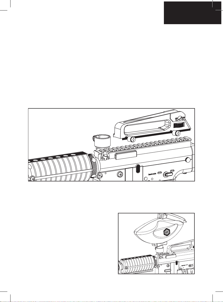
INSTALLING CARRYING HANDLE W/SIGHT
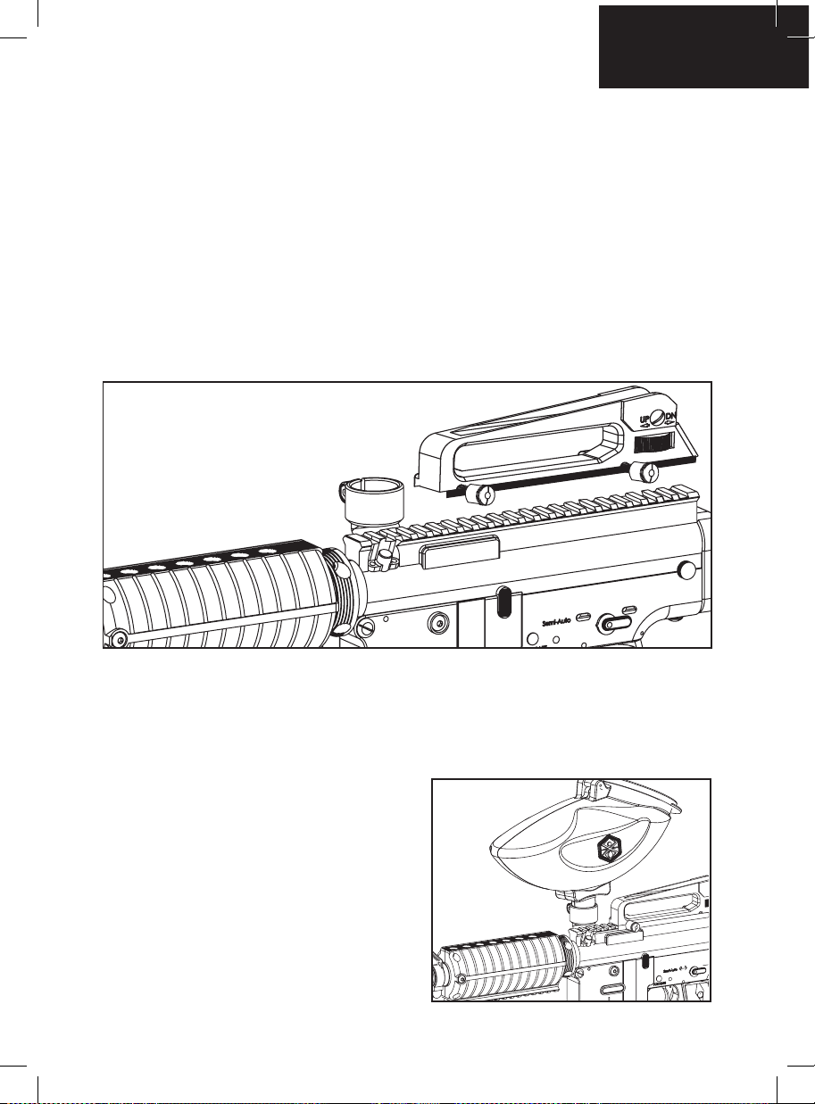
Loosen both Locking Screws from the Carrying Handle Sight.
Place the Carrying Handle Sight to t above the Picatinny Body Rail. Make sure to align the Locking Plate with
the Carry Handle Sight. Then Fasten both Locking Screws. NOTE: The Carrying Handle Sight adjusting wheel
should be on the Right side and at the rear of the Receiver.
INSTALLING / REMOVING A PAINTBALL LOADER
IMPORTANT: The Barrel must be installed before loading
the Magazine or Paintball Loader. Attach an electronic or
gravity paintball loader to the Markers Feed Neck and
tighten the set screw. Only use .68 caliber paintballs
through the loader.
Loosen the Feed Neck set screw and remove the
electronic or gravity paintball loader. When removing the
loader make sure to remove all paintballs. CAUTION:
There may be paintballs in the Markers breach; take a
couple of shots in a safe direction to make sure the Barrel
and Receiver are empty.
4
Page 8
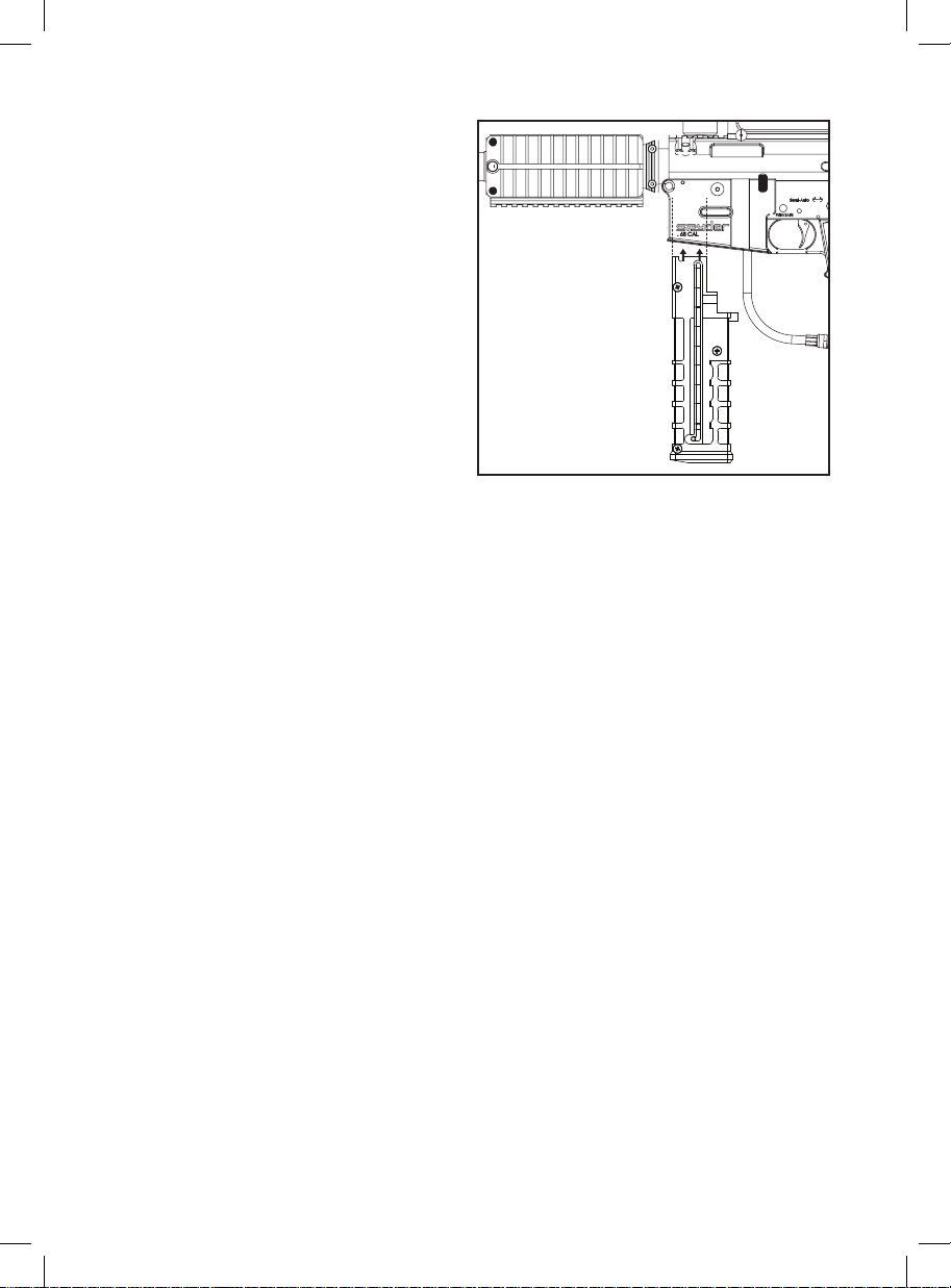
LOADING PAINTBALLS IN THE MAGAZINE
IMPORTANT: The Barrel must be installed before
loading the Magazine or Paintball Loader.
IMPORTANT: Always have the marker on safe mode
until you are ready to operate.
IMPORTANT: Storing paintballs in a temperature
of 59° F (15°C) or below will affect the quality and
performance of the paintballs.
IMPORTANT: The magazine should be clean and
free of any shell fragment or dirt before loading
paintballs.
WARNING: DO NOT freeze the paintballs.
STEP 1 Slide the ball pusher towards the bottom of
the magazine and turn to the left to place the guide
pin in the locked position.
STEP 2 Load only 9 Paintballs (.68 Cal.) or 9 First
Strike Paintballs. NOTE: First Strike Paintballs can only be loaded in a specic direction in the First Strike
Capable (FSC ) 9 round Straight Magazine. HELPFUL TIP: The Fin of the First Strike Paintball is facing towards
the Receiver and the Rounded Body of the First Strike Paintball is facing towards the Barrel. NEVER mix First
Strike™ Paintballs and (. 68cal) Paintballs inside a Straight Magazine.
STEP 3 Follow the guided line to insert the Magazine straight into the Trigger Housing until it snaps into position.
STEP 4 Turn the ball pusher pin right to the un-locked position. IMPORTANT: If the ball pusher pin is not
released, the spring will not push the paintballs into the markers breach.
RELEASING THE MAGAZINE
Push the magazine release button located on the right side of the markers handle. This will allow the magazine
to slide out the handle. NOTE: Never take apart the magazine release button unless the magazine does not
release from the trigger frame.
IMPORTANT: NEVER slam the magazine into the receiver, excessive force inserting the magazine will push a
paintball pass the ball detents and roll out the barrel.
NOTE: Do not store magazine (s) loaded with paintballs for an extended period of time as the pressure from the
magazine spring will cause the paintballs to de-form and not shoot properly.
HELPFUL TIP: Older paintballs left for a period of time are not recommended for use or you will experience
premature paintball breakage and poor accuracy.
FIRST STRIKE™ PAINTBALL WARNING
Paintball is an extreme sport. Misuse of the equipment can cause serious injury or death. Due to the Physical
attributes of First Strike paintballs, the following must be adhered to. When using First Strike Paintballs in
Spyder paintball markers, all players must wear the following: full-face paintball goggles that protect the face,
eyes, and ears, cap or hood f or the back of the head, neck protector, long sleeve top, pants and full nger
gloves. Markers must be chronographed using First Strike paintballs to insure that the velocity remains under
300 fps or the velocity required by the playing eld. Do not shoot any player at a distance less than 30 ft. (10
yards), or the minimum distance required by the playing eld. Please read the complete marker manual and
follow all of the important safety guidelines given by Spyder. The use of the First Strike paintballs may not be
allowed at all elds. Check the eld’s paintball rules before use.
5
Page 9
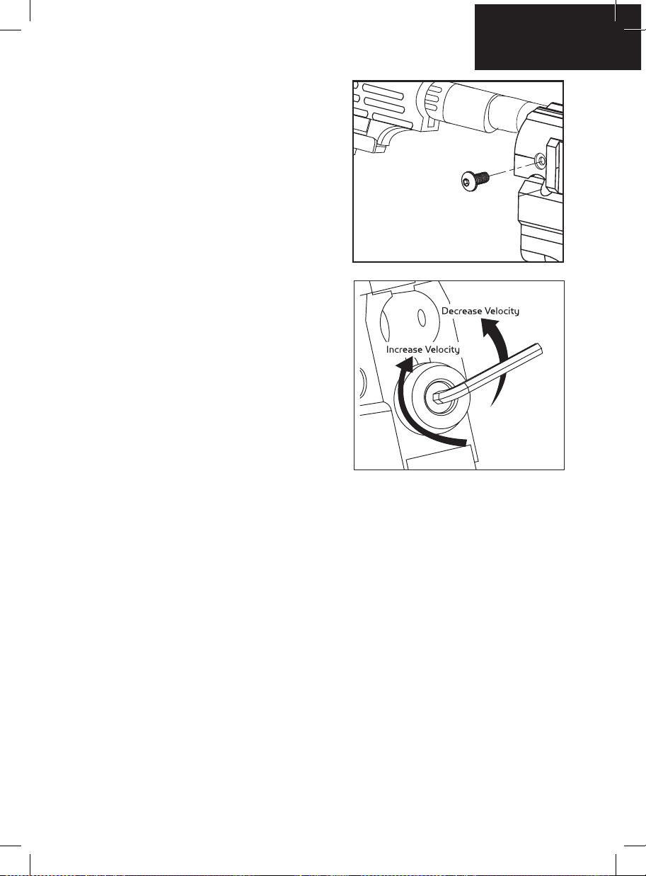
INSTALLING / REMOVING A SHOULDER STOCK
Place the Shoulder Stock in the top breach of the Receiver
behind the Venturi Bolt. Once the Shoulder Stock is in place
secure the Stock with the set screw provided, then tighten
with the Allen wrench.
To adjust the length of the Shoulder Stock press and hold
the Lever for adjustment. Once the Lever is released this will
lock into position.
Loosen the set screw on the right side of the Receiver with
the Allen wrench. Then remove the Shoulder Stock out the
top breach of the Receiver. HELPFUL TIP: The Shoulder
Stock must be removed if intended to clean the marker.
(SEE DISASSEMBLE/REASSEMBLE AND CLEANING OR
REAR INTERNALS).
VELOCITY ADJUSTMENT INCREASE / DECREASE
To INCREASE your velocity FPS (Feet Per Second) using
the Allen wrench turn the Velocity Adjuster / Spring Guide
clockwise.
To DECREASE your velocity FPS (Feet Per Second) using
the Allen wrench turn the Velocity Adjuster / Spring Guide
counter-clockwise.
NOTE: The velocity of this paintball Marker ranges from
approximately 220 - 300 feet per second (fps). Velocities
will uctuate or vary due to paintball size, climate condition,
altitude, type of air source and variance in spring tension
from manufacturing.
English
WARNING
• The recommended Velocity speed should be no greater
than 300 fps. Not doing so can cause serious injury if the Velocity is dangerously high.
• Paintball markers are not intended to shoot any person less than 30 feet.
• Never point a loaded marker at any person who is not wearing the proper face protection.
• Never at any point should you look down the barrel, whether the marker is loaded or not.
• Using a paintball marker outside a non designated paintball eld can be illegal, and is subject to law
enforcement penalties if property damage is caused by the user.
A JAMMED PAINTBALL
In the event of a paintball break and the Venturi Bolt jams, follow these steps to help un-jam the Marker. The
Markers breach is located where the barrel starts to thread in the Receiver and underneath the Markers feed
neck. Before attempting to un-jam the Venturi Bolt you should always have your Goggles or Safety Glasses on.
Make sure the Marker is in the SAFE MODE position before attempting to un-jam the Venturi Bolt. Remove the
CO2/Compressed Air Tank before attempting to un-jam the Marker. Remove all paintballs from the Magazine
and Loader. Have the barrel removed from the Receiver to allow the paintball(s) to exit. With enough force on
the Cocking Knob, pull back to release the Venturi Bolt from the jammed position. Another method is to use
a “Straight Shot Squeegee” or the end of a wood dowel rod; push against the face of the Venturi Bolt with
enough force to release the jammed Bolt. Always clean the paint from the breach and barrel to enhance the
performance of your Marker.
DANGER: Never look down the barrel of the Marker when loaded or unloaded. Remove the attached CO2/
Compressed Air Tank before attempting to un-jam the Venturi Bolt. NOTE: Never use a metal rod or screwdriver
as a tool to push on the Venturi Bolt, anything metal will scratch and damage the inside of the Marker.
6
Page 10
HOW TO CLEAN THE MARKER
DANGER: Do not look down the Marker barrel. Always wear goggles specically designed for paintball use
while working on your paintball Marker.
IMPORTANT: Always have the Marker on SAFE MODE before disassembly. Remove all paintballs and air
source from the Marker before performing any maintenance.
HELPFUL TIP: Follow these steps to help clean/remove Marker parts should in the event of a paintball break.
SQUEEGEE CLEANING OF THE BARREL AND BREACH
Using a Stick Squeegee (not included)
If the Venturi Bolt is in the un-cocked position you need to re-cock the Marker. Slide a stick squeegee down
the barrel until it reaches the Markers breach. Then remove the stick squeegee out of the barrel. This should
wipe clean any paint residue that could have broken inside the Marker. HELPFUL TIP: Make sure the Markers
breach is clean and clear of any paintball shell fragments or dirt. Repeat this step if the paint residue did not
wipe clean after the rst attempt.
Using a Pull Squeegee (not included)
Twist off the barrel and slide a Pull Squeegee squeegee from the threaded end so the swab is the last portion
of the squeegee out of the barrel tip. Grab hold the tail of the cable squeegee and pull. This should wipe clean
any paint residue that could have broken in the barrel. HELPFUL TIP: Make sure the Markers breach is clean
and clear of any paintball shell fragments or dirt. Repeat this step if the paint residue did not wipe clean after
the rst attempt.
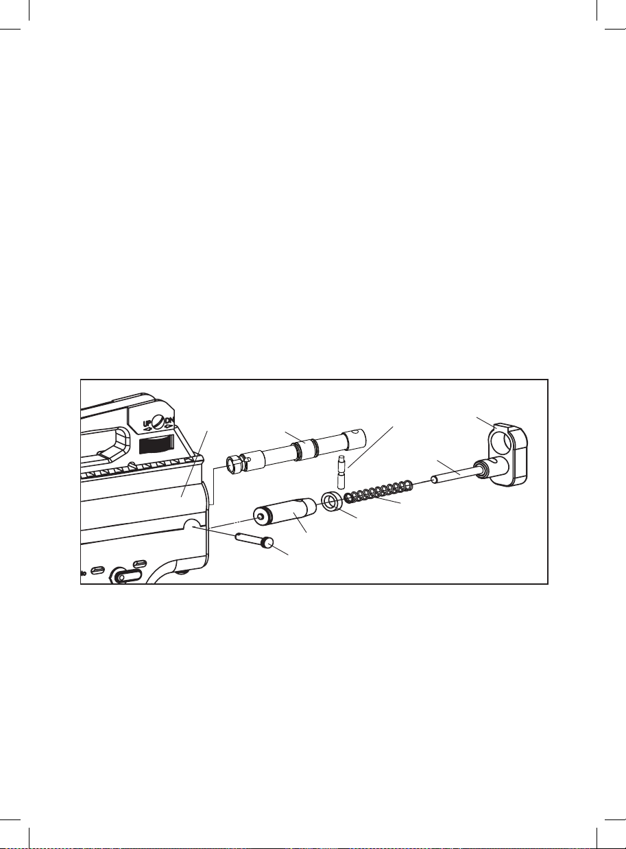
DISASSEMBLE / REASSEMBLE REAR INTERNALS
Receiver (1)
Venturi Bolt (4)
Bolt Pin (3)
Striker Plug (62)
Velocity Adjuster (59)
Striker Spring (58)
Striker Buer (57)
Striker Bolt (56)
Quick Disconnect Pin (61)
DISASSEMBLE REAR INTERNALS
HELPFUL TIP: The Stock should not be attached to the Receiver when removing Rear Internals.
STEP 1. Pull out the Disconnect Pin from the Receiver. HELPFUL TIP: Remove the Striker Plug while the
marker in the un-cocked position this will prevent the internals from springing out because the Striker Spring
is compressed.
STEP 2. Remove the Striker Plug with the Striker Spring and Striker Buffer out the back of the Receiver.
STEP 3. Tilt the back of the marker into your hands ready catch the Venturi Bolt and Striker Bolt from the back
of the Receiver. HELPFUL TIP: When the internals are removed it would be wise to clean any dirt or paint from
the inside of the Receiver with a squeegee and wipe the Venturi Bolt clean with a rag or paper towel. Apply
some paintball gun oil on Striker O-ring periodically. IMPORTANT: It is not necessary to disassemble the rear
internals for basic maintenance unless the Striker O-ring needs to be replaced.
7
Page 11
English
REASSEMBLE REAR INTERNALS
STEP 1. Join both Venturi Bolt and Striker Bolt thru the rear of the Receiver with the O-ring on the Striker
Bolt facing towards the front of the Marker. NOTE: When inserting both parts, apply nger pressure behind the
Venturi Bolt and at the same time pull on the Trigger to allow entry of the both parts.
STEP 2. Insert the Striker Buffer ush at the lower end of the Receiver and place the Striker Spring thru the
Striker Buffer.
STEP 3. Place the Striker Plug w / Velocity Adjuster & Spring Guide to the rear of the Receiver.
STEP 4. Insert the Disconnect Pin to secure the Striker Plug in place. WARNING: Before/after use of the Marker,
make sure to fasten all screws. Screws may become loose due to vibration. Loose screws can be dangerous
and cause injury.
To assure marker is assembled properly, follow the schematic drawing or position parts in order during
disassembly. Parts assembled backwards or improper parts installed will / can cause the marker to malfunction.
WARNING: Never attempt to remove the markers internals while the CO2 / Compressed Air Tank is attached.
Make sure to remove all paintballs and loader before disassembling the marker.
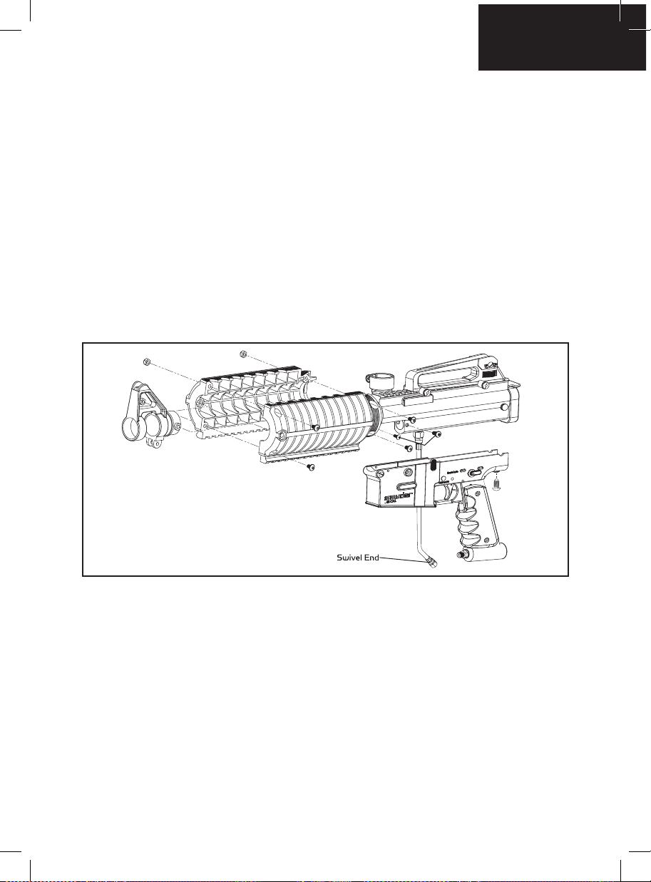
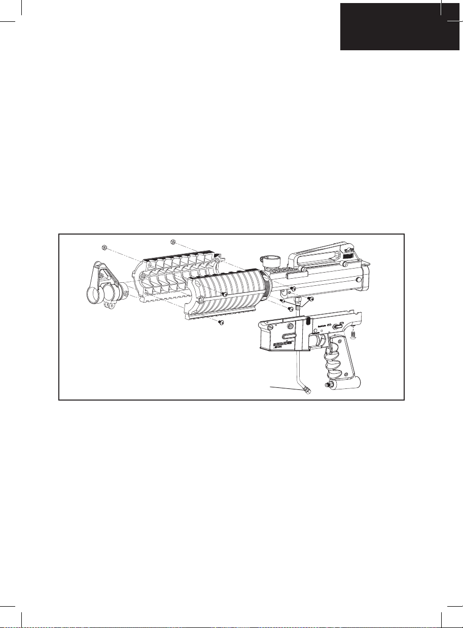
BARREL SHROUD REMOVAL
STEP 1. Using a 1/2inch or 13mm open end or and adjusted wrench loosen the Swivel End of the hose.
STEP 2. Remove the Three Screws that hold the Trigger Housing to the Receiver. One the Screw is located at
the rear of the Receiver. The other Two additional Screws are on the Left and Right side of the Trigger Housing.
STEP 3. Once the Trigger Housing is removed from the Receiver loosen all of the Six Screws from the Shroud.
This will allow the Shroud to split in half.
HELPFUL TIP: Please note how the parts are removed for easy reassembly.
8
Page 12
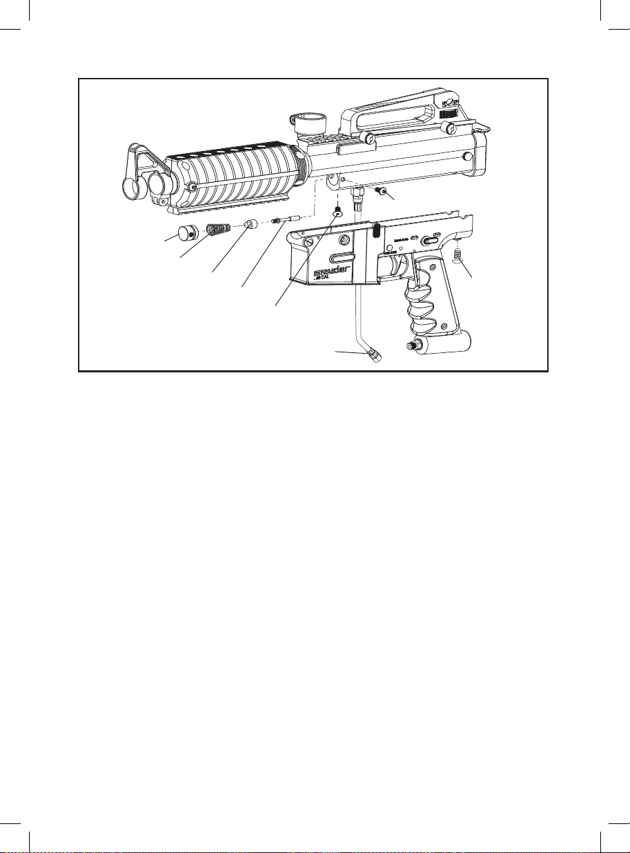
Screw (30)
Reservoir Plug (46)
Valve Spring (50)
Eko™ Cup Seal (51)
Eko™ Pin Valve (52)
Screw (63)
Swivel End (36)
Screw (65)
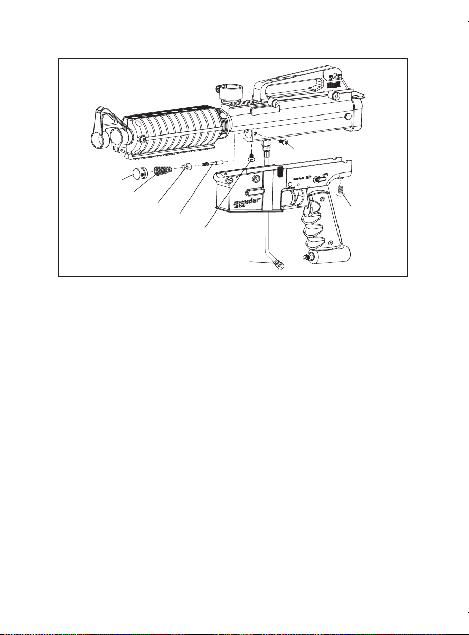
EKO™ CUP SEAL REMOVAL
The following steps will provide easy access to the Eko™ Cup Seal. The sign of a worn out Eko™ Cup Seal is
the presence of CO2 / Compressed Air leaking down the barrel.
HELPFUL TIP: Do not rush or skip any of the steps for proper disassembly of the marker. Remove the barrel
before starting.
STEP 1. Using a 1/2 inch/13 mm open end or an adjustable wrench to loosen the swivel end of the Hose.
NOTE: A Plastic Washer is inside the female swivel end of the Hose. Make sure you do not lose this part.
STEP 2. Remove the three screws that hold the Trigger Frame to the Reciever. One screw is located at the rear
of the Trigger Frame. Two additional screws are on the left and right side of the Trigger Frame.
STEP 3. Remove the Vertical Screw that is holding the Reservoir Plug. Once the Reservoir Plug has been
removed the Valve Spring, Eko™ Valve Pin, Eko™ Cup Seal Guide and Eko™ Cup Seal will be attached.
STEP 4. Detach the Valve Spring from the Reservoir Plug, and then unscrew the Eko™ Cup Seal from the
Eko™ Valve Pin. Replace the Eko™ Cup Seal with a new one supplied in the Spare Parts Kit.
Once these steps have been completed, replace the damaged Eko™ Cup Seal and reassembly all parts back
in the Receiver. HELPFUL TIP: Please note how the parts are removed for easy reassembly.
CAUTION: Use the proper Allen wrenches to fasten all screws and never apply more force than necessary.
IMPORTANT: Always remove the Air Tank before any disassembly of your marker. Do not remove the Eko™
Valve Body unless specic Eko™ Valve Body repairs are needed. Do not remove the Eko™ Valve Body with a
screwdriver as it will damage the Eko™ Valve Body Lip.
9
Page 13

English
AIR LEAK FROM THE HOSE LINE
1. If air is leaking from the opposite ends of the hose ttings will need to retighten to snug.
2. The female end of the hose must have a Plastic Washer installed inside the Hose collar and be tightened
properly. IMPORTANT: The Hose line supplied has metric female ends. This will not install into American 1/8”
(NPT) threaded ttings. If installed incorrectly, it is possible to damage the attachment ttings and hose line.
3. The o-ring on the top of the foregrip has a torn o-ring or needs to be replaced. HELPFUL TIP: You can use a
urethane bottle o-ring for replacement if not able to replace with a stock o-ring.
DEALING WITH AN AIR LEAK
Down The Barrel or Out of The Trigger Frame
1. Eko™ Cup Seal is bad and needs to be replaced. (SEE Eko™ Cup Seal REMOVAL GUIDE)
2. The Valve Body lip is nicked or scratched and needs to be replaced. NOTE: Never remove the Valve Body
unless specic repairs are needed.
3. Air leaking through the Receiver and out of the Trigger Frame. The back o-ring on the Valve Body is damaged
and needs to be replaced.
TROUBLESHOOTING
Dealing with a Paintball Breakage
1. If the weather temperature is below 59°F (15°C) or above 86°F (30°C) paintballs can become brittle and not
hold up to the Markers velocity and outside temperature. Paintballs have a shelf life and can become too fragile
for use. Paintballs can take a different shape in time so would be wise to size the paintball with your barrel. Dirt
or broken paint shell fragments in the barrel can cause the Marker to have re-cocking issues. Using a squeegee
thru the upper portion of the Receiver will remove most of the dirt or broken shell fragments.
2. If the loader has double fed a paintball in the barrel/breach and the Marker was red. This can break paint
out of the barrel.
3. If you over shoot the paintball loader and in middle travel have wedged a paintball in the breach this could
cause a paintball breakage.
4. Velocity adjustment is too high and needs to be lowered to proper velocity (fps) speed.
RECOCKING RELATED ISSUES
1. Need lubrication on the Striker O-ring. (SEE DISASSEMBLE/REASSEMBLE AND CLEANING OF REAR
INTERNALS).
2. Striker O-ring is damaged or missing. Replace with a new Spyder approved Striker O-ring. NOTE: The Striker
O-ring can not be substituted with another type of o-ring.
3. The pressure in the tank is too low and possibly needs to be relled.
4. Dirt or broken paint shell fragments in the Receiver can cause the Marker to have recocking issues. Using a
squeegee thru the upper portion of the Receiver will remove most of the dirt or broken shell fragments. Should
this issue continue, remove the Markers internals
10
Page 14
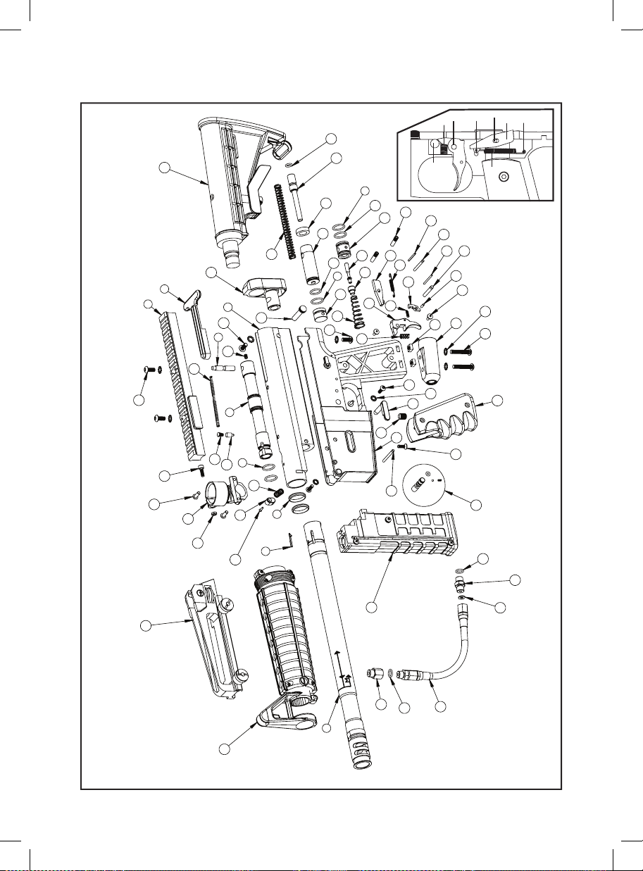
MR6™ SCHEMATICS
20
9
8
22
16
21
46
44 45
38
60
59
5
57
56
58
62
1
61
22
3
13
10
4
11
5
12
28
6
14
27
65
54
53
52
55
51
5
49
37
50
38
63
19
37
48
47
46
42
43
40
23
67
45
39
30
26
41
25
71
31
68
42
47
43
44
64
69 70
24
19
11
66
18
7
29
17
32
2
15
34
33
33
36
35
Page 15
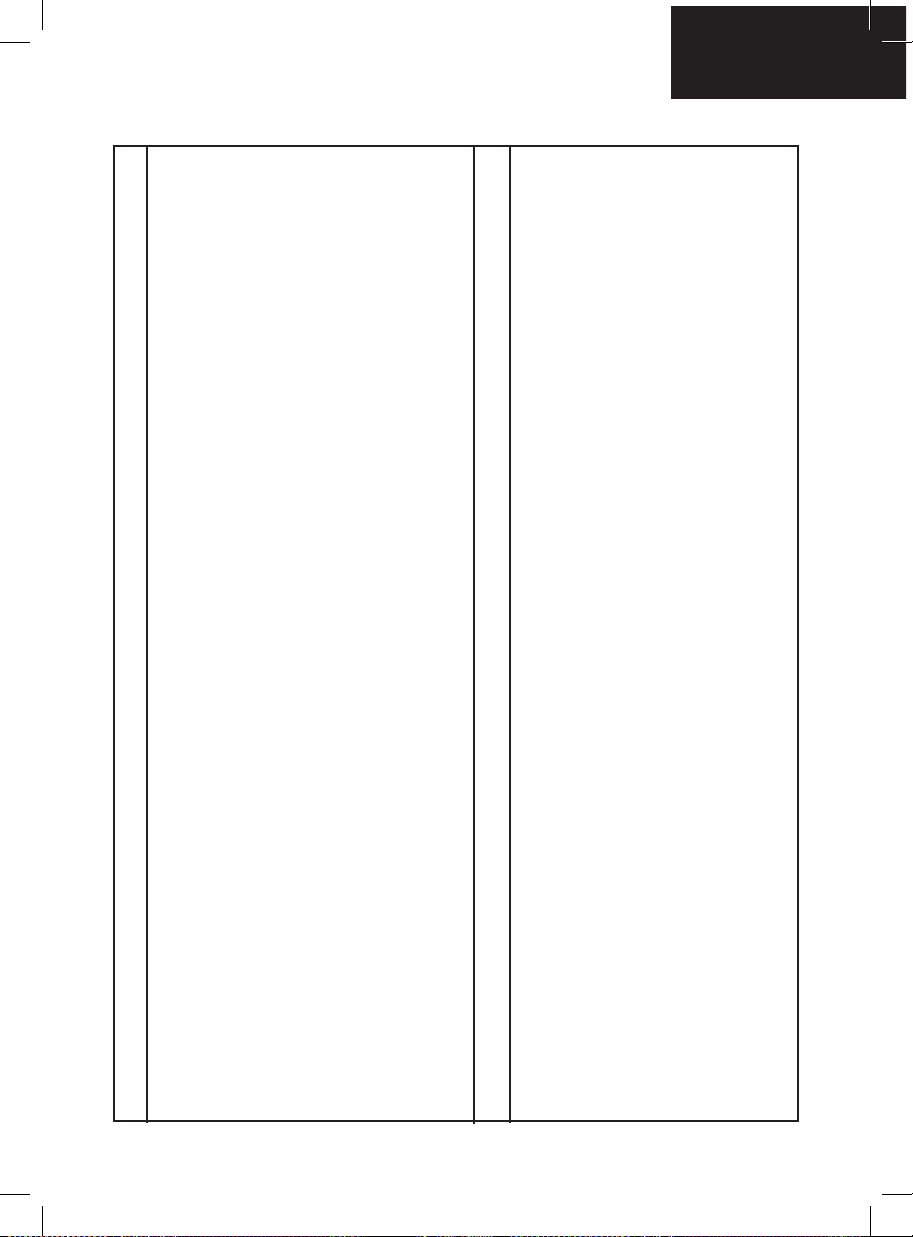
MR6™ PARTS LIST
MR6 Receiver
1
MR6 Barrel Assembly
2
Bolt Pin
3
MR6 Venturi Bolt
4
Bolt / Reservoir Plug / Valve body O-Ring
5
Flat Barrel O-ring
6
MR6 Barrel Ball Stopper
7
Picatinny Body Rail
8
Rear Charging Handle
9
Rear Charging Handle Spring
10
Barrel Guide Pin Spring
11
Barrel Guide Pin
12
Bolt Pin Set Screw
13
MR6 Feed Neck
14
MR6 Barrel Shroud Assembly
15
Feed Neck clamp Screw
16
MR6 Magazine Assembly
17
Carrying Handle Mount w/Sight
18
MR6 Safety Button Assembly
19
Adj Car Shoulder Stock
20
MR6 Feed Neck Screw
21
Picatinny Body Rail /Adj Car Stock Screw
22
MR6 Trigger Frame
23
Wrap Around Rubber Grip
24
C/A Adapter
25
MR6 Magazine Release Lock
26
MR6 Magazine Release Button
27
MR6 Magazine Release Spring
28
Magazine Release Button Screw
29
Trigger Frame Side Screw
30
Trigger Frame Side Lock Washer
31
Metric Female to Standard Male Adapter
32
O-Ring
33
Hose
34
Plastic Washer
35
Male to Female Adapter
36
Single Trigger
37
Trigger Spring
38
Interrupter
39
Interrupter Spring
40
Interrupter Pin
41
Sear
42
Sear Spring
43
MR6 Trigger Roll Pin (large)
44
MR6 Sear Stop Roll Pin (small)
45
MR6 Sear Roll Pin (med)
46
Secondary Roll Pin (small)
47
Trigger Frame Grip Inserts
48
Reservoir Plug MR6
49
Valve Spring
50
EkoTM Cup Seal
51
EkoTM Valve Pin
52
EkoTM Valve Body
53
Front Valve Body O-Ring
54
Striker O-Ring
55
Striker Bolt
56
Striker Buffer
57
Striker Spring
58
Velocity Adj Spring Guide
59
Velocity Adj Spring Guide O-Ring
60
Quick Disconnect Pin
61
MR6 Striker Plug
62
Valve Body Screw(A)
63
Wrap Around Rubber Grip Screw
64
Trigger Frame Bottom Screw
65
Feed Neck clamp Nut
66
MR6 Magazine Release Pin
67
Vertical Screw
68
Adapter Screw
69
Adapter External Tooth Lock Washer
70
Adapter Nut
71
English
12
Page 16

WARRANTY REPAIR RETURN PROCEDURE
A returned product must be accompanied by a Return Authorization (RA) number on the
outside of the box; please call Paintball Solutions at 1.800.220.3222 to obtain an RA number
before shipping product to Spyder Paintball. All warranty returns must be accompanied by the
operator’s name, address, and telephone number. Include operator’s fax and e-mail if possible.
Operator must remove all paintballs before shipping, and must pack product securely to avoid
appear to work correctly. Ship to: Spyder Paintball, 11723 Lime Kiln Rd., Neosho, MO 64850.
Spyder Paintball is a brand of KEE Action Sports, LLC. Design rights & all rights reserved. All
patterns, drawings, photographs, instructions or manuals remain the intellectual property of the
ASTM International, formerly known as the American Society for Testing and Materials (ASTM),
is a globally recognized leader in the development and delivery of international voluntary
consensus standards used around the world to improve product quality, enhance safety,
facilitate market access and trade, and build consumer condence. ASTM International, 100
Barr Harbor Drive, PO Box C700, West Conshohocken, PA, 19428-2959 USA, www.astm.org
PATENT(S): See www.paintballsolutions.com/patents © 2013-2014 KEE Action Sports. All
rights reserved. This KEE Action Sports product is protected by one or more United States and
International patents. KEE Action Sports Trademarks, Designs and Copyrights are protected by
damage during shipping. Include a brief description of what does not
manufacturer. All rights will be strictly enforced.
one or more United States patents and International Law.
For more information contact KEE Action Sports at [email protected]
13
Page 17
Marqueur De Paintball Semi Automatique De Calibre .68
TABLE DES MATIERES
IMPORTANTES CONSIGNES DE SECURITE
MISE EN ROUTE
INSTALLER / DÉMONTER / MONTER LE BARIL MR6™
UTILISATION APPROPRIEE DU BOUCHON DE CANON
INSTALATION DE LA BOUTEILLE DE GAZ
INSTALLATION DE LA POIGN ÉE DE TRANSPORT W/SIGHT
INSTALLATION/RETRAIT D’UN CHARGEUR DE BILLES
CHARGEMENT DES BILLES DANS LE CHARGEUR
INSTALLATION/RETRAIT D’UNE CROSSE D’ÉPAULE
REGLAGE DE LA VELOCITE, AUGMENTER / DIMINUER
BILLE COINCEE DANS LA DESCENTE DE BILLE
DEMONTAGE/NETTOYAGE/ REMONTAGE DES PIECES INTERNES
BARIL SUAIRE ENLEVEMENT
GUIDE DE DEMONTAGE DU Eko™ CUP SEAL
FUITE D´AIR DU TUYAU
DÉPANNAGE
SCHÈMAS DU SPYDER MR6™
LISTE DES PIECES DU SPYDER MR6™
POLICE DE GARANTIE
Français
15
16
17
17
18
18
18-19
20
20
20
21
21-22
22
23
24
24
25
26
27
Page 18
RÈGLES DE SÉCURITÉ POUR L’UTILISATION D’UN LANCEUR DE PAINTBALL
1.
Ne pas utiliser à moins que toute personne à portée de tir ne porte une protection oculaire, du visage et
des oreilles conçue spécifiquement pour arrêter les billes de paintball, en accord avec les spécifications
ASTM F1776.
2.
Ne jamais pointer le marqueur vers toute personne ne portant pas de masque de paintball en accord avec
les spécifications ASTM F1776.
3.
Ne jamais modifier d’aucune façon le système d’air pressurisé ou le cylindre de votre marqueur.
4.
Gardez le marqueur en position Sécurité jusqu’à ce que vous soyez prêt à tirer.
5.
N’utilisez jamais autre chose que les billes de calibre .68. N’essayez pas de tirer avec des billes usagées.
6.
Traitez chaque marqueur comme s’il était chargé.
7.
Ne regardez jamais dans le canon d’un marqueur de paintball.
8.
Gardez votre doigt loin de la gâchette jusqu’à ce que vous soyez prêt à tirer.
9.
Ne pointez jamais le marqueur vers quelque chose que vous ne voulez pas viser.
10.
Gardez le système de blocage du canon sur le canon lorsque vous ne tirez pas.
11.
Gardez le marqueur en position Sécurité lorsqu’il n’est pas utilisé.
12.
Enlevez toujours les billes et la source d’air avant de démonter le marqueur.
13.
Une fois la source d’air enlevée, pointez le marqueur dans une direction sécuritaire et purgez jusqu’à ce
que le marqueur soit dégazé.
14.
Stockez le marqueur déchargé et dégazé dans un endroit sécuritaire.
15.
Suivez les avertissements se trouvant sur la source d’air concernant la manipulation et le stockage.
16.
Ne tirez pas sur des objets fragiles comme des fenêtres.
17.
Mesurez toujours la vitesse de votre marqueur avant de jouer, et ne tirez jamais à des vitesses excédant
91.44m/s (300pi/s)
18.
Ne faites pas de vandalisme.
19.
Certaines billes peuvent tâcher les surfaces poreuses comme la brique, le stuc et le bois.
ATTENTION : Ceci n’est pas un jouet. Une mauvaise utilisation peut entraîner des blessures ou la mort
Une protection oculaire spécialement conçue pour le paintball doit être portée par l’utilisateur et toutes les
personnes à portée de tir. Doit avoir 18 ans ou plus pour acheter. Les personnes de moins de 18 ans doivent
avoir la permission d’un adulte. LISEZ LE MANUEL AVANT TOUTE UTILISATION
.
15
Page 19

Français
MISE EN ROUTE
ATTENTION: Toujours garder son lanceur éteint ou sur le mode “safe” jusqu’a son utilisation.
1. Spyder recommande d’avoir le lanceur en position “SAFE” avant l’utilisation. Pour verrouiller la sécurité, pousser
le bouton du coté “PUSH SAFE” de la poignée. Cela enclenchera la sécurité. Pour désengager la sécurité d’une
manière sécurisée, pointer le lanceur dans une direction sans risque et poussez le bouton du coté “PUSH FIRE”
de la poignée.
2. Placer le bouche canon sur le canon par précaution quand le lanceur n’est pas utilisé.
3. Attacher la bouteille de CO2 ou d’air comprimé à l’adaptateur. CONSEIL: Assurez-vous que la bouteille de CO2
ou d’air comprimé soit remplie avant de la monter au lanceur. Vissez la bouteille dans le sens des aiguilles d’une
montre dans l’adaptateur jusqu’à ce que la valve s’ouvre. Si vous constatez une fuite entre la valve de la bouteille
et l’adaptateur, remplacez les joints toriques uréthane. NOTE: Les joints toriques uréthane ne sont pas fournis
dans le kit de réparation, ces joints ne sont pas faits pour la valve de la bouteille. IMPORTANT: Vous ne devriez
jamais avoir à utiliser des outils pour monter ou démonter la bouteille de CO2 ou d’air comprimé sur l’adaptateur.
4. Attacher Joindre le Magazine pour le logement de déclencheur ou joindre le chargeur de Paintball au cou de
marqueurs nourrir et serrer la vis sans. NOTE: Remplissage Loader avec seulement (.68 cal.) remplissage/
paintballs Magazine avec (.68 cal.) ou billes First Strike™. Ne jamais mélanger First Strike ™ Paintballs et
(.68cal) balles de peinture à l’intérieur d’un Magazine en ligne droite.
5. Armement du marqueur. Armez le marqueur en tirant d’armement vers l’arriere jusua ce que la culasse en FS
Venturi s’enclenche ATTENTION: Si vous lâchez la culasse avant qu’elle ne s’enclenche, un coup pourrait partir.
6. Enlever le bouchon de canon. PRECAUTION: Si le bouton de sécurité est enclenché, le lanceur est en mode « live
», appuyer sur la détente déclenchera le tir d’une bille. IMPORTANT: Toujours tester le lanceur dans une direction
sure ou dans une aire de jeu approprié et vous ne devrez que tester les capacités du lanceur.
7. Effectuez un TEST DE VELOCITÉ (fps). Tourner l’ajusteur de vélocité / guide ressort dans le sens des aiguilles
d’une montre augmentera la vélocité (fps). NOTE: Votre marqueur est destiné à être utilisé uniquement sur un
complexe de paintball avec les protections appropriées à la pratique du paintball. IMPORTANT: Spyder
recommande l’utilisation d’un chronographe pour s’assurer que la vélocité du marqueur soit en dessous de 300
pieds par seconde (fps).
8. Lorsque terminée, retirer toutes les balles de peinture du Magazine et le chargeur. ATTENTION: Il est
possible qu’une bille de paintball se trouve dans la descente de billes; appuyez sur la détente à quelques reprises
en pointant le marqueur dans une direction sûre pour vous assurer que le canon et la descente de billes soient
vides.
9. Replacez le bouchon de canon / chaussette à canon, sur le canon quand le lanceur n est pas utilisé. Ceci évitera
tout tir accidentel.
10. Spyder recommande de mettre le marqueur en position “SAFE” après utilisation.
11. Dévissez la bouteille de CO2/air comprimé de l’adaptateur C/A du marqueur. Dévissez dans le sens opposé
des aiguilles d’une montre. ATTENTION: Ne jamais exposer une partie du corps non protégée sous le trou
d’évacuation de CO2/air comprimé de l’adaptateur C/A lorsque vous enlevez la bouteille. Ceci peut entraîner des
risques de brûlure venant de l’évacuation du gaz. IMPORTANT: Vous ne devriez jamais avoir besoin de recourir à
l’utilisation d’outils pour détacher la bouteille de CO2/air comprimé.
12. Placez le marqueur dans un sac de paintball ou dans un endroit sûr. CONSEIL PRATIQUE: Due aux vibrations
les vis peuvent se desserrer et se perdre. Assurez-vous de resserrer toutes les vis avant et après utilisation du
marqueur. Il est conseillé de lubrier le marqueur avant et après chaque utilisation, surtout lorsque le marqueur
n’a pas servi pendant un long laps de temps. Ajoutez quelques gouttes d’huile pour marqueur de paintball sur le
joint de marteau. (Voir guide de démontage/ remontage). Avant de ranger le marqueur, assurez vous d’avoir votre
marqueur en position désarmée. Ceci évitera que le ressort principal ne perde sa tension.
IMPORTANT
• Tir vitesse variera en fonction de l'altitude, les conditions climatiques et le type de paintball utilisé. Premiers tours
de grève auront une vitesse supérieure à une paintball régulière de 0,68 Calibre.
• Elle peut se révéler dangereuse sur environ 300 pieds (100 mètres) de la portée de tir.
• Avant d’utiliser votre marqueur dans une partie, vous devez toujours réaliser un « TEST DE SECURITE DE
VITESSE ». Celui-ci ne peut se faire qu’à l’aide d’un appareil de test, que l’on appelle « chronographe de vitesse
» et ne peut être réalisé que chez un distributeur ou sur un terrain de paintball local. NOTE: Ce produit est conçu
pour être utilisé à une vitesse inférieure à 300 pieds par secondes (fps). Les marqueurs de paintball ne sont pas
conçus pour être tirés à une portée de 30 pieds (10 mètres).
• Ce marqueur de paintball peut avoir un surplus de gaz après le retrait de la bouteille de CO2 / air
comprimé. Veuillez retirer toutes les billes et décharger le reste de gaz en toute sécurité.
• Ne conservez jamais une bouteille de CO2 / air comprimé xée au marqueur
16
Page 20
INSTALLER / DÉMONTER / MONTER LE BARIL MR6
Pour installer le baril vous devez aligner la èche centrale du baril avec la èche du viseur (voir schéma A). Une
fois alignés, insérez le baril.
Pour monter l’alimentation “Magazine”, tournez le baril dans le sens inverse des aiguilles d’une montre en
vériant que la èche sur le baril (M ) soit alignée avec la èche du viseur (voir schéma B).Pour monter
l’alimentation “Loader”, tournez le baril dans le sens des aiguilles d’une montre en vériant que la èche sur le
baril (L ) soit alignée avec la èche du viseur (voir schéma C).
Pour démonter le baril, alignez la èche centrale du baril avec la èche du viseur (voir schéma D). Une fois
alignés, retirez le baril.
UTILISATION APPROPRIEE DU BOUCHON DE CANON
Le bouchon de canon est une partie essentielle à la sécurité de votre équipement .Le bouchon de canon est un
outil servant a empêcher les billes de sortir du canon. Mal utilisé le bouchon de canon ne sert à rien.
BOUCHON DE CANON TYPE “CHAUSSETTE”
Placer la chaussette du bouchon de canon par dessus le bout du canon et tirez l’élastique pour l’accrocher à
l’arrière du lanceur.
Ajuster l’élastique de manière à ce que la tension soit sufsante pour arrêter une bille sortant du canon. NOTE:
si l’élastique est trop long, vous pouvez faire des noeuds pour raccourcir l’élastique.
BOUCHON DE CANON TYPE “BOUCHON RIGIDE”
Insérer le bouchon de canon au bout du canon en vous assurant qu il tient bien avant de charger les billes dans
le lanceur et de visser la bouteille de gaz au lanceur.
Le bouchon de canon doit rester fermement en place avec une certaine résistance. NOTE: le bouchon de
canon ne doit pas être facile a enlever et il faut toujours inspecter les joints toriques pour s’assurer qu’ils ne
soient pas abîmés ou coupées.
N’enlevez le bouchon de canon que quand vous êtes prêt à jouer ou si un agent de sécurité du terrain vous
donne l’autorisation de le faire.
Gardez toujours votre bouchon de canon sur votre lanceur après avoir ni de jouer et gardez le, même après
avoir vidé le lanceur des billes de paintball et démonté la bouteille de gaz de votre lanceur.
ATTENTION : Pensez à inspecter régulièrement votre bouchon de canon, si vous observez une usure,
remplacez-le immédiatement. Toujours avoir votre bouchon de canon sur votre lanceur pour prévenir un
éventuel accident qui pourrait causer de blessures grave ou même la mort.
17
Page 21
Français
DEMONTER UNE BOUTEILLE DE CO2/AIR COMPRIME
Dévisser la bouteille de CO2 ou d’air comprimé de l’adaptateur en tournant dans le sens inverse des aiguilles
d’une montre. CONSEIL: Après l’utilisation vous devriez toujours démonter la source de gaz de votre lanceur.
Quand la bouteille est démontée de l’adaptateur, un excèdent de gaz est purge par le dessous. PRECAUTION:
Ne jamais exposer la peau en dessous de l’adaptateur où se trouve le trou d évacuation lors du démontage.
Ceci peut provoquer des brûlures de la peau au moment de la purge du gaz. IMPORTANT: Vous ne devriez
jamais avoir à utiliser des outils pour monter ou démonter la bouteille de CO2 ou d’air comprimé sur l’adaptateur.
MONTER UNE BOUTEILLE DE CO2/AIR COMPRIME
Visser fermement la bouteille de CO2 ou d’air comprimé dans le sens des aiguilles d’une montre dans
l’adaptateur. CONSEIL: Toujours vérier que la bouteille de CO2 ou d’air comprimé soit pleine et que le joint
uréthane soit présent sur la valve pour éviter des fuites. IMPORTANT: Vous ne devriez jamais avoir à utiliser des
outils pour monter ou démonter la bouteille de CO2 ou d’air comprimé sur l’adaptateur.
INSTALLATION DE LA POIGN ÉE DE TRANSPORT W/SIGHT
Desserrez les deux vis de verrouillage de la vue transportant de gérer.
Placez la vue de gérer transportant adaptée au-dessus du Rail de corps Picatinny. Assurez-vous d’aligner la
plaque de verrouillage avec la vue transportant de gérer. Puis serrez les deux vis de verrouillage. NOTE: La
transportant gérer vue ajustant roue devrait être sur le côté droit et à l’arrière du récepteur.
INSTALLATION / RETRAIT D’UN CHARGEUR DE BILLES
IMPORTANT: Le canon doit être installé avant de charger
le Magazine ou le chargeur de Paintball.
Fixer un chargeur de billes électronique ou à gravité au
distributeur de marqueurs et serrer les vis de pression.
Serrer les deux accessoires pour assurer une bonne
xation. N’utiliser que des billes de calibre 0.68 dans le
chargeur.Desserrer les vis du distributeur de marqueurs
et retirer le chargeur de billes électronique ou à gravité.
Lors du retrait du chargeur, s’assurer que toutes les billes
soient retirées. ATTENTION : Il peut rester des billes dans
le conducteur du marqueur ; donner quelques coups
dans une direction sans danger pour vérier que le
canon et la culasse sont vides.
18
Page 22
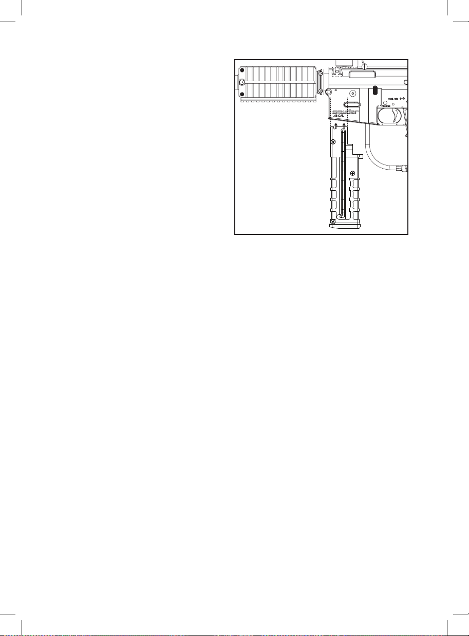
CHARGEMENT DES BILLES DANS LE
CHARGEUR
IMPORTANT: Le canon doit être installé avant de
charger le Magazine ou le chargeur de Paintball.
IMPORTANT: Tant que vous n’êtes pas prêt à jouer,
le marqueur doit toujours être en MODE SECURITE.
IMPORTANT: Stocker les billes de paintball à une
température de 15° C (59° F) en affectera la qualité
et la performance.
IMPORTANT: Le chargeur doit être propre et vous
devez tirez tout fragment de cartouche ou poussière
avant de charger les billes de paintball.
AVERTISSEMENT: NE congelez PAS les billes de
paintball.
ÉTAPE 1. Slide le placeur de balle vers le bas du
magazine et tourner à gauche pour placer la broche
de guide est en position verrouillée.
ÉTAPE 2. Chargez seulement 9 billes (calibre 68) ou 9 billes First Strike. REMARQUE: Les billes First Strike
peuvent seulement être chargées dans un sens spécique dans le chargeur à 9 cartouches capacité First Strike
(FSC). CONSEIL UTILE: L’ailette des billes First Strike est orientée vers le récepteur et le corps arrondi de la
bille First Strike est orienté vers le canon.. Ne jamais mélanger First Strike ™ Paintballs et (.68cal) balles de
peinture à l’intérieur d’un Magazine en ligne droite.
ÉTAPE 3. Insérez le magazine directement dans le logement de déclencheur. NOTE : Le Magazine devrait être
installé directement dans le logement de déclencheur avec facilité. Assurez-vous que le magazine est dans une
position de composant logiciel enchable verrouillé.
ÉTAPE 4. Une fois que la dernière bille a été chargée dans le chargeur, relâchez l’arrêt du chargeur. IMPORTANT:
Si la goupille de guidage du poussoir de billes n’est pas relâchée, le ressort ne poussera pas les billes dans le
conducteur des marqueurs.
RELÂCHER LE CHARGEUR
Appuyez sur le bouton de libération magazine situé sur le côté droit de la poignée de marqueurs. Ceci permettra
le magazine de glisser sur la poignée. NOTE: Jamais prendre part le magazine relâchez le bouton, à moins que
le magazine ne libère pas de l’armature de déclencheur.
IMPORTANT: Ne démontez JAMAIS le chargeur ou vous ANNULEREZ la garantie de Spyder.
NOTE: Ne stockez pas le(s) chargeur(s) chargé(s) de billes pendant une longue période, car la pression du
ressort du chargeur entraînera la déformation des billes et le marqueur ne tirera plus correctement.
CONSEIL UTILE: L’utilisation de billes plus anciennes stockées pendant une longue période n’est pas
recommandée, car elles éclateront prématurément et vos tirs seront peu précis.
AVERTISSEMENT POUR LES BILLES FIRST STRIKE™
Le paintball est un sport extrême. Une mauvaise utilisation de cet équipement peut causer des blessures graves ou
la mort. En raison des caractéristiques physiques des billes First Strike, les points suivants doivent être respectés:
Lorsque vous utilisez les billes First Strike dans les lanceurs Spyder, tous les joueurs doivent être équipés des
éléments suivants : des lunettes paintball intégrales qui protègent votre visage, vos yeux et vos oreilles, une casquette
ou une cagoule pour le derrière de la tête, un protège-cou, un haut à manches longues, un pantalon et des gants
couvrant la totalité des doigts. Les lanceurs doivent être chronographés avec les billes First Strike an d’assurer que
la vitesse est en dessous de 300 fps ou de la vitesse exigée par le terrain de paintball. Ne tirez sur aucun joueur à une
distance inférieure à 30 pieds (environ 10 m), ou à la distance minimum exigée par le terrain de jeu.
Veuillez lire l’intégralité du manuel du lanceur et suivre les consignes de sécurité données par Spyder, ou consultez
les consignes de sécurité sur www.spyder.tv/safety. L’utilisation des billes First Strike n’est peut être pas autorisée
sur tous les terrains. Consultez les règles du terrain de paintball avant de les utiliser.
19
Page 23
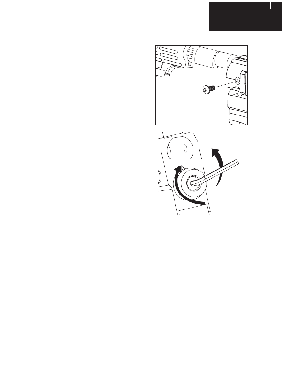
Français
INSTALLTION / RETRAIT D’UNE CROSSE D’ÉPAULE
Placez la crosse d’épaule dans le conducteur supérieur du
récepteur derrière la culasse Venturi. Une fois la crosse
d’épaule en place, bloquez-la avec les vis de pression
fournies, puis serrez celles-ci avec la clé hexagonale.
Desserrez les vis sur le côté droit du récepteur avec la
clé hexagonale. Retirez ensuite la crosse d’épaule du
conducteur supérieur du récepteur. CONSEIL UTILE:
La crosse d‘épaule doit être retirée avant de nettoyer le
marqueur. (VOIR DÉMONTAGE/ MONTAGE ET NETTOYAGE
OU PARTIES INTERNES ARRIÈRE).
REGLAGE DE LA VELOCITE,
AUGMENTER / DIMINUER
Pour AUGMENTER la vélocité FPS (feet per second = pieds
par seconde) utilisez la clef six pans et tournez la pièce
VELOCITY ADJUSTER/SPRING GUIDE dans le sens des
aiguilles d’une montre.
Pour
DIMINUER la vélocité, tournez dans le sens inverse
des aiguilles d’une montre.
NOTE: La pièce VELOCITY ADJUSTER/SPRING GUIDE
ne se démonte pas par l’arrière du bouchon de la pièce
STRIKER PLUG.
DIMINUER LA VÉLOCITÉ
AUGMENTER LA VÉLOCITÉ
MISE EN GARDE
• La vélocité de ne doit jamais excédée 300 fps, une
vélocité plus importante est dangereuse et peu causée de
sérieuses blessures.
• Les lanceurs de paintball ne sont pas faits pour être
utilisés contre des personnes à moins de 25 pieds.
• Ne jamais pointer le lanceur en direction d’une personne qui ne porte pas une protection faciale adaptée a
la pratique du paintball.
• Ne regardez jamais dans le canon à aucun moment que le lanceur soit chargé ou non.
• Utiliser un lanceur de paintball en dehors d’une zone faite pour le paintball peut être illégal, et peut être
passible de poursuites si des dégâts ont été causés par son utilisateur.
BILLE COINCEE DANS LA DESCENTE DE BILLE
Dans l’éventualité ou une bille serait coincée par la culasse et la bloquerai, suivez cette procédure pour
débloquer la bille. La chambre de la bille est située juste avant le canon en dessous de la descente de bille.
Avant d’essayer de débloquer la bille vous devez porter votre masque de protection. Assurez vous d’avoir mis
le lanceur en position off ou enclenché la sécurité. Démontez la bouteille de CO2 ou d’air comprimé, enlevez
le chargeur de billes, et assurez vous qu’il ne reste plus de billes dans le lanceur. Dévissez le canon du lanceur
pour permettre à la bille coincée de sortir. Tirez avec une force sufsante sur la goupille de réarmement vers
l’arrière jusqu’à débloquer la culasse. Si vous n’arrivez toujours pas par ce moyen à décoincer la culasse, une
autre méthode consiste a prendre une tige de nettoyage droite et rigide ou bien une tige en bois et pousser
la culasse vers l’arrière en poussant avec la tige depuis l’avant du lanceur en faisant attention que la surface
en contact avec le devant de la culasse soit plat pour ne pas endommager la culasse ou l’alésage du corps.
Après avoir débloqué la culasse d’une manière ou d’une autre, nettoyez la chambre de la bille et la culasse si
nécessaire pour assurer des performances optimums.
IMPORTANT: ne regardez jamais dans le canon que le lanceur soit chargé ou non.
Toujours démonter la source de gaz avant d’entreprendre le décoinçage de la culasse.
NOTE: Ne jamais utiliser une tige en métal pour pousser la culasse, cela pourrait rayer le corps ou la culasse.
20
Page 24
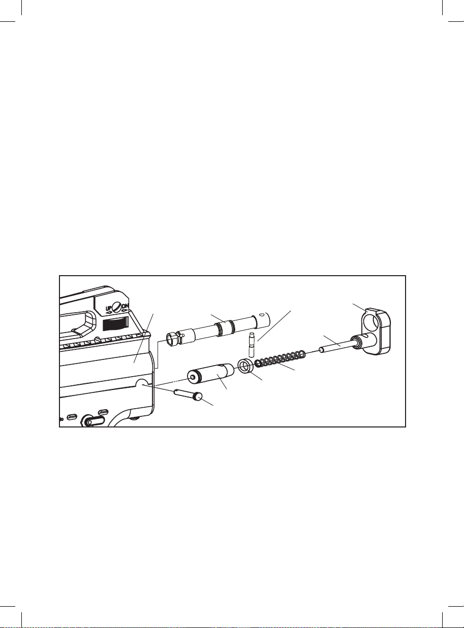
NETTOYAGE DU MARQUEUR
DANGER : Ne pas regarder dans le canon du marqueur. Toujours porter des lunettes spécialement conçues
pour les marqueurs de paintball, dès que vous manipulez votre marqueur.
IMPORTANT : Toujours mettre le marqueur en MODE SÉCURITÉ avant de le démonter. Retirer toutes les billes
et toute source d’air éventuelle du marqueur avant d’effectuer les tâches de maintenance.
CONSEIL UTILE : Suivre ces étapes pour enlever la bille / nettoyer le marqueur, en cas de rupture de bille.
NETTOYAGE DU CANON ET DU CONDUCTEUR AVEC UNE RACLETTE
Utilisation d’une tige de nettoyage rigide (non fournie)
Si la culasse Venturi est en position non armée, vous devez réarmer le marqueur. Faire glisser la tige rigide vers
le bas du canon jusqu’au conducteur du marqueur. Retirer ensuite la tige du canon. Ceci devrait nettoyer tout
résidu de peinture qui aurait pénétré à l’intérieur du marqueur. CONSEIL UTILE : S’assurer que le conducteur
du marqueur est propre, sans fragments de cartouche de bille ni poussière. Répéter cette étape s’il reste
encore des résidus de peinture.
Utilisation d’une tige de nettoyage pourvue d’un coton-tige (non fournie)
Dévisser le canon et faire glisser le coton-tige en partant de l’extrémité letée, an que le bout du coton-tige
atteigne le bout du canon. Saisir le bout de la tige de nettoyage et tirer. Ceci devrait éliminer tout résidu de
peinture qui aurait pénétré à l’intérieur du canon. CONSEIL UTILE : S’assurer que le conducteur du marqueur
est propre, sans fragments de cartouche de bille ni poussière. Répéter cette étape s’il reste encore des résidus
de peinture.
DEMONTAGE/REMONTAGE ET NETTOYAGE DES PIECES INTERIEURES ARRIERES
(1)
(4)
(3)
(58)
(57)
(56)
(61)
(62)
(59)
DEMONTAGE DES PIECES INTERNES ARRIERES
CONSEIL UTILE: La Stock ne doit pas être attaché du Receveur lors du retrait les Internes Arrière.
ÉTAPE 1: Retirez la tige de débranchement du récepteur. CONSEIL UTILE : Enlevez l’obturateur du percuteur
lorsque le marqueur est en position désarmée ; l’obturateur du percuteur étant comprimé, les pièces internes
ne sortiront pas brusquement.
ÉTAPE 2: Retirer l’obturateur du percuteur, le ressort du percuteur et le butoir du percuteur de l’arrière du
récepteur.
ÉTAPE 3: Inclinez l’arrière du marquer dans vos mains pour attraper la culasse Venturi et le verrou du percuteur
situés à l’arrière du récepteur.
CONSEIL: nettoyez l’intérieur du corps a l’aide d’une tige, nettoyez également le marteau et la culasse en
remettant quelque goûtes d’huile sur le joint torique rouge du marteau.
IMPORTANT: il n’ est pas necessaire de demonter les pieces internes pour un entretient normal a moins que
vous deviez changer le joint torique du marteau (striker O-ring).
21
Page 25
Français
REMONTAGE DES PIECES INTERNES ARRIERES
ÉTAPE 1: Joignez-vous à FS FS Venturi Bolt et boulon au poste d’attaquant à l’arrière du récepteur avec le
joint torique sur le boulon de l’attaquant face vers l’avant du mar queur. NOTE: Lors de l’insertion de chacune
des deux parties, une pression du doigt derrière la culasse FS FS Venturi Bolt et en même temps tirer sur la
gâchette pour permettre l’entrée des deux parties.
ÉTAPE 2: Insérer la chasse au poste d’attaquant à l’extrémité inférieure du récepteur et place au printemps au
poste d’attaquant à la mémoire tampon au poste d’attaquant.
ÉTAPE 3: La culasse Venturi étant dirigée vers l’arrière du récepteur, faites glisser le bouton d’armement et
dévissez-le de la culasse.
ÉTAPE 4: Inclinez l’arrière du marquer dans vos mains pour attraper la culasse Venturi et le verrou du percuteur
situés à l’arrière du récepteur.
MISE EN GARDE: avant et après l’utilisation, vériez que toutes les vis soient bien serrées, une vis desserrée
peut cause de sérieuses blessures.
BARIL SUAIRE ENLEVEMENT
L’EXTRÉMITÉ PIVOTANTE
ÉTAPE 2: Utilisez une clé à molette ou réglable de 13 mm/1/2 pouces pour desserrer l’extrémité pivotante du
tuyau. NOTE : Une rondelle en plastique se trouve à l’intérieur de l’extrémité pivotante femelle du tuyau. Ne
perdez surtout pas cette pièce.
ÉTAPE 2: Supprimer les trois vis qui xent le déclencheur logement au récepteur. Une vis est situé à l’arrière du
récepteur. Les deux autres vis supplémentaires sont sur la gauche et la droite de l’habitation de déclencheur.
ÉTAPE 3: Une fois le logement déclencheur est retiré du récepteur desserrer toutes les Six vis de carénage.
Ceci permettra le Suaire de scinder en deux.
Astuce utile : Veuillez noter comment les pièces sont supprimées pour réassemblage facile.
22
Page 26
(30)
(46)
(50)
(51)
(52)
(63)
(36)
(65)
GUIDE DE DEMONTAGE DU EKO™ CUP SEAL
Les étapes suivantes vous permettrons d’accéder facilement au « Eko™ Cup Seal ». Une fuite d’air ou de CO2
au canon est le signe d’ un « Eko™ Cup Seal » abîmé.
ÉTAPE 1: Utilisez une clé à molette ou réglable de 13 mm/1/2 pouces pour desserrer l’extrémité pivotante du
tuyau.
ÉTAPE 2: Supprimer les trois vis qui xent le déclencheur logement au récepteur. Une vis est situé à l’arrière du
récepteur . Les deux autres vis supplémentaires sont sur la gauche et la droite de l’habitation de déclencheur.
ÉTAPE 3: Lorsque le bouchon de la chambre a été enlevé, le ressort de valve, la tige de Eko™ Cup Seal, le
guide de Eko™ Cup Seal et le Eko™ Cup Seal devrait être attaché.
ÉTAPE 4: Détachez le ressort de valve du bouchon de la chambre, et ensuite dévissez le Eko™ Cup Seal de la
tige de valve. Remplacez le Eko™ Cup Seal avec un neuf fourni dans le kit de pièces détachées.
Une fois que toutes les étapes ont été exécutées, remplacer le « Eko™ Cup Seal » endommagé et remontez les
pièces au lanceur. ASTUCE: Notez comment les pièces se démontent pour faciliter le remontage.
ATTENTION: Utiliser la clef Allen à la bonne taille de la vis et ne jamais serrer les vis plus fort qu’il n’est
nécessaire.
IMPORTANT: Toujours démonter la bouteille de sur le lanceur avant de démonter le lanceur. Ne pas démonter
la valve à moins qu’une réparation de la valve soit nécessaire. N’utilisez pas de tourne vis pour démonter la
valve, cela pourrait faire des marques sur la valve qui provoqueraient des fuites. NOTE: La vis de valve doit
être démontée
23
Page 27

Français
FUITE D’AIR DU TUYAU
1. Si la fuite d’air se situe à l’extrémité opposée du tuyau, les raccords auront besoin d’être resserrés pour être
bien ajustés.
2. L’extrémité femelle du tuyau doit être équipée d’une rondelle en plastique à l’intérieur du collier de serrage et
doit être bien serrée. IMPORTANT : Le tuyau fourni a des extrémités femelles métriques. Il ne sera pas possible
de le brancher à un raccord leté américain 1/8” (NPT). En cas de mauvaise installation, les raccords et le tuyau
risquent d’être endommagés.
3. Le joint torique en haut du Foregrip est endommagé ou doit être remplacé. CONSEIL UTILE : S’il est
impossible de le remplacer par un joint en stock, vous pouvez le remplacer par un joint torique en uréthane.
EN DE FUITE D’AIR
Dans le canon ou hors du cadre de la gâchette.
1. Le joint de culasse est en mauvais état et doit être remplacé. (VOIR LE GUIDE DE RETRAIT DU JOINT DE
CULASSE)
2. Le rebord du corps du clapet est éraé ou rayé et doit être remplacé. NOTE : Ne jamais retirer le corps du
clapet, sauf si des réparations sont vraiment nécessaires.
3. Fuite d’air dans le récepteur et par le cadre de la gâchette. Le joint torique arrière du corps du clapet est
endommagé et doit être remplacé.
DÉPANNAGE
En cas d’éclatement des billes
1. Si la température est inférieure à 15 °C (59 °F) ou supérieure à 30 °C (85 °F), les billes peuvent devenir
cassantes et ne pas supporter la vitesse des marqueurs et la température extérieure. Les billes ont une durée
de vie et peuvent devenir trop fragiles pour être utilisées. Les billes peuvent changer de forme avec le temps
et il est recommandé de les calibrer selon votre canon. Des fragments de cartouche de peinture sales ou
cassés dans le canon peuvent provoquer des problèmes de réarmement du marqueur. L’utilisation d’une tige
de nettoyage dans la partie supérieure du récepteur permettra d’enlever la plupart de ces fragments sales ou
cassés.
2. Si deux billes se trouvent à l’intérieur du canon/conducteur en même temps et que le marqueur a été armé,
les billes peuvent être éjectées du canon.
3. Si le chargeur de billes est trop chargé et qu’une bille est coincée à mi-chemin dans le marqueur, les billes
risqueraient d’éclater.
4. La vitesse est trop élevée et doit être réduite à la bonne vitesse (fps).
Recocking Related Issues
1. Il faut lubrier le joint torique du percuteur. (VOIR DÉMONTAGE/MONTAGE ET NETTOYAGE DES PARTIES
INTERNES ARRIÈRE).
2. Le joint torique du percuteur est endommagé ou manquant. Le remplacer par un nouveau joint torique de
percuteur homologué Spyder. NOTE : Le joint torique du percuteur ne peut pas être remplacé par un autre type
de joint torique.
3. La pression dans la bouteille est trop faible et il faut probablement la remplir à nouveau.
4. La présence de fragments de cartouche de peinture sales ou cassés dans le récepteur peut provoquer des
problèmes de réarmement du marqueur. L’utilisation d’une tige de nettoyage dans la partie supérieure du
récepteur permettra d’enlever la plupart de ces fragments sales ou cassés. Si ce problème persiste, retirer les
parties internes du marqueur pour les nettoyer complètement. (VOIR DÉMONTAGE/MONTAGE ET NETTOYAGE
OU PARTIES INTERNES ARRIÈRE).
24
Page 28
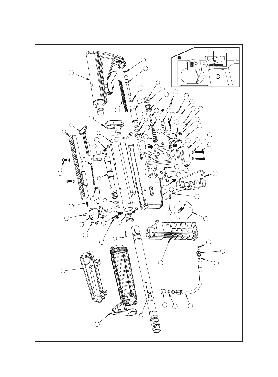
SCHÈMAS DU MR6™
20
9
8
22
16
21
46
44 45
38
60
59
5
57
56
58
62
1
61
22
3
13
10
4
11
5
12
28
6
14
27
65
54
53
52
55
51
5
49
37
50
38
63
19
37
48
47
46
42
43
40
23
67
45
39
30
26
41
25
71
31
68
42
47
43
44
64
69 70
24
19
25
66
18
7
29
17
32
2
15
34
33
33
36
35
Page 29
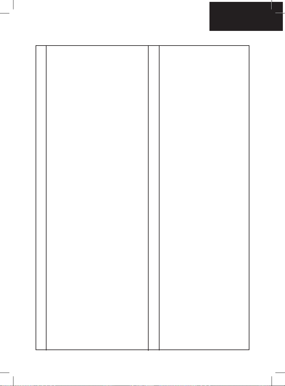
LISTE DES PIECES DU MR6™
MR6 Receiver
1
MR6 Barrel Assembly
2
Bolt Pin
3
MR6 Venturi Bolt
4
Bolt / Reservoir Plug / Valve body O-Ring
5
Flat Barrel O-ring
6
MR6 Barrel Ball Stopper
7
Picatinny Body Rail
8
Rear Charging Handle
9
Rear Charging Handle Spring
10
Barrel Guide Pin Spring
11
Barrel Guide Pin
12
Bolt Pin Set Screw
13
MR6 Feed Neck
14
MR6 Barrel Shroud Assembly
15
Feed Neck clamp Screw
16
MR6 Magazine Assembly
17
Carrying Handle Mount w/Sight
18
MR6 Safety Button Assembly
19
Adj Car Shoulder Stock
20
MR6 Feed Neck Screw
21
Picatinny Body Rail /Adj Car Stock Screw
22
MR6 Trigger Frame
23
Wrap Around Rubber Grip
24
C/A Adapter
25
MR6 Magazine Release Lock
26
MR6 Magazine Release Button
27
MR6 Magazine Release Spring
28
Magazine Release Button Screw
29
Trigger Frame Side Screw
30
Trigger Frame Side Lock Washer
31
Metric Female to Standard Male Adapter
32
O-Ring
33
Hose
34
Plastic Washer
35
Male to Female Adapter
36
Single Trigger
37
Trigger Spring
38
Interrupter
39
Interrupter Spring
40
Interrupter Pin
41
Sear
42
Sear Spring
43
MR6 Trigger Roll Pin (large)
44
MR6 Sear Stop Roll Pin (small)
45
MR6 Sear Roll Pin (med)
46
Secondary Roll Pin (small)
47
Trigger Frame Grip Inserts
48
Reservoir Plug MR6
49
Valve Spring
50
EkoTM Cup Seal
51
EkoTM Valve Pin
52
EkoTM Valve Body
53
Front Valve Body O-Ring
54
Striker O-Ring
55
Striker Bolt
56
Striker Buffer
57
Striker Spring
58
Velocity Adj Spring Guide
59
Velocity Adj Spring Guide O-Ring
60
Quick Disconnect Pin
61
MR6 Striker Plug
62
Valve Body Screw(A)
63
Wrap Around Rubber Grip Screw
64
Trigger Frame Bottom Screw
65
Feed Neck clamp Nut
66
MR6 Magazine Release Pin
67
Vertical Screw
68
Adapter Screw
69
Adapter External Tooth Lock Washer
70
Adapter Nut
71
Français
26
Page 30

PROCEDURE DE RETOUR SOUS GARANTIE EN VUE D’UNE RÉ
Un produit retourné doit être accompagné d’une autorisation de retour (RA) collée
sur l’emballage du colis. Veuillez téléphoner préalablement à Paintball Solutions, Tél:
1.800.220.3222 pour obtenir un numéro RA, avant tout envoi de produits à Spyder Paintball,
en retour. Tous les retours sous garantie doivent être accompagnés du nom de l’utilisateur,
son adresse et numéro de téléphone. Inclure aussi le numéro de fax et l’adresse électronique.
Veillez à retirer les toutes les billes et protégez bien votre produit pour éviter toute dégradation
lors du transport. Accompagnez-le d’une petite description de ce qui ne semble pas
Spyder Paintball, 11723 Lime Kiln Rd., Neosho, MO 64850 USA.
Spyder Paintball est une marque de KEE Action Sports, LLC. Droits de Design & Tous droits
réservés. Tous les modèles, dessins, photographies, instructions ou les guides restent la
propriété intellectuelle du fabricant. Tous droits seront strictement appliquées.
ASTM International, anciennement connue sous le nom American Society for Testing and
Materials (ASTM), est un leader mondialement reconnu dans le développement et la livraison
de normes consensuelles volontaires internationaux utilisés dans le monde pour améliorer
la qualité des produits, améliorer la sécurité, faciliter l’accès au marché et le commerce, et
renforcer la conance des consommateurs. ASTM International, 100 Barr Harbor Drive, PO Box
C700, West Conshohocken, PA, 19428-2959 États-Unis, www.astm.org.
BREVET(S): consultez www.paintballsolutions.com/patents © 2013-2014 KEE Action Sports.
Tous droits réservés. Ce produit KEE Action Sports est protégé par un ou plusieurs brevets
aux Etats-Unis et dans le monde. Les logos, marques et copyrights KEE Action Sports
sont protégés par un ou plusieurs brevets aux Etats-Unis ou lois internationales. Pour plus
d’informations, contactez KEE Action Sports à [email protected]
fonctionner correctement. Envoyez le tout à:
27
Spyder Paintball 11723 Lime Kiln Rd. Neosho, MO 64854
www.spyder.tv
Spyder Paintball is à brand of KEE Action Sports, LLC
Page 31

Français
Page 32

 Loading...