

Page 1

.68 Caliber Semi-Automatic Paintball Marker
USER MANUAL
English
Français
Page 2
.68 C ali b e r S e m i-A u t oma t i c P a i ntb a l l M a r ker
TABLE OF CONTENTS
IMPORTANT SAFETY GUIDELINES 1
OPERATION GUIDE / START UP 2
8 STEPS TO START AND PLAY 3-4
English
CO2 / COMPRESSED AIR TANK WARNINGS 5
INSTALLING A CO2 / COMPRESSED AIR TANK 5-6
PROPER USE OF YOUR BARREL BLOCKING DEVICE 6
INSTALLING / REMOVING A PAINTBALL LOADER 6
INSTALLING / REMOVING A SHOULDER STOCK 7
VELOCITY ADJUSTMENT INCREASE/DECREASE 7
A JAMMED PAINTBALL IN THE BREACH 7
HOW TO CLEAN THE MARKER 8
DISASSEMBLE / REASSEMBLE AND CLEANING OF REAR INTERNALS 8-9
CUP SEAL REMOVAL GUIDE 9-10
TROUBLESHOOTING 10
MR4™ PARTS LIST 11
MR4™ SCHEMATIC 12
WARRANTY STATEMENT 13
Page 3

English
IM PORTANT SAFETY GUIDELINES
WARNING
This paintball Marker is NOT a toy. Misuse can cause serious injury or death.
•
Kingman recommends that the customer be at least 18 years of age to purchase this product. Person
•
under 18 years of age must have adult supervision when using this product.
Read this User manual before using this product.
•
Any modications or tampering of original factory parts or use non authorized aftermarket
•
accessories will void all warranties and liabilities from Kingman.
Keep the barrel blocking device on Marker when not shooting/playing.
•
To ensure proper adjustment of velocity Feet Per Second (fps), Kingman strongly recommends using
•
a chronograph for paintball use located or purchased at most paintball stores and paintball elds.
The discharges of paintballs are high velocity and high impact that can cause serious injuries or
death if misused.
Before/after use of the Marker, check and make sure all screws are securely tightened. Loose
•
screws may prevent the Marker from functioning properly. A paintball Marker NOT properly
maintained can be dangerous and can cause serious injury or death.
Any person using this product or within range of this product while it is in use MUST wear EYES/
•
FACE, EARS PROTECTION designed specically for the sport of paintball. This includes, but is not
limited to, performing a maintenance/velocity check and during target practice.
Kingman reminds the user that SAFETY IS YOUR RESPONSIBILITY. Protect your eyes/face and
•
ears at all times. Kingman will not be held liable for injuries or death sustained when failing to follow
the safety guidelines.
Never shoot or point your Marker at a person that is not in a designated paintball facility and without
•
proper paintball EYES/FACE/EARS PROTECTION. The protection includes and not limited to the
protection of eyes, face, ears, neck and head. Avoid shooting underneath the paintball goggles.
DO NOT point or shoot at any Law Enforcement Ofcer.
•
DO NOT remove the Blaze Orange Muzzle Tip. This identies the paintball marker is NOT a rearm.
•
Treat every paintball Marker as if it were loaded.
•
Never look down the barrel of a loaded or unloaded Marker.
•
Always keep the paintball Marker in SAFE MODE until ready to operate.
•
Always remove the air source and all paintballs from the Marker, includes paintballs inside the breach
•
of the Marker, before disassembly.
Fire only .68 caliber paintballs with this product. The use of any foreign objects will VOID all
•
warranties and liabilities from Kingman.
Always make certain the bolt of the Marker is in the un-cocked position when not shooting/playing.
•
Using a paintball Marker outside of a non designated paintball eld can be illegal, and is subject to
•
law enforcement penalties if property damage is caused by the user.
Never point or shoot your Marker at an animal.
•
Never point the barrel toward yourself while playing, running or stumbling to avoid shooting
•
underneath your paintball goggles.
Wear appropriate dress to avoid any exposure of skin to protect you when playing paintball games.
•
Transfer this User’s Manual upon change of Marker ownership.
•
Please visit www.spyder.tv for the latest User Manual updates.
•
OP ERATI ON GUIDE / STAR T UP
1. Always attach a barrel blocking device over the tip of the barrel for safety precautions when not shooting/
playing.
2. Kingman recommends having the Marker in the SAFE MODE position before use. To operate, push the safety
button from the “PUSH SAFE” side of the Trigger Frame. This will position the Marker in a lock SAFE MODE.
To disengage the safety button in a safely manner, point the Marker in a safe direction, and push the safety
button towards the opposite side of the Trigger Frame. CAUTION: Do not disengage safety button until step 6.
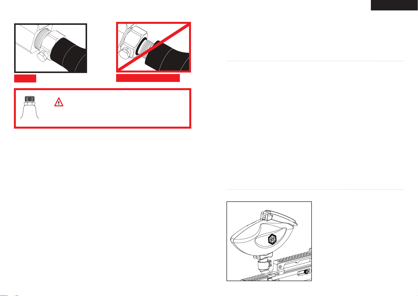
3. Attach a CO2/Compressed Air Tank to the Markers C/A adapter. Using a CO2/Compressed Air Tank rmly
tighten clockwise to the Markers C/A adapter until it is snug. HELPFUL TIP: Make sure to have the CO2/
Compressed Air Tank lled before attaching. NOTE: O-rings in the Markers parts kit are NOT supplied to attach
with a CO2/Compressed Air Tank. IMPORTANT: You should never need to use any hand tool to attach a CO2/
COMPRESSED AIR TANK to the Markers C/A adapter. (SEE CO2/COMPRESSED AIR TANK WARNING)
4. Attach the paintball loader to the Markers clamping feed neck and tighten the set screw. NOTE: Fill your
paintball loader with only .68 caliber paintballs.
5. Cocking the Marker. On the left side of the Receiver there is a Cocking Knob which you need to pull rearward
until the Venturi Bolt latches. CAUTION: Should you let go of the Cocking Knob before it latches, your Marker
may re.
6. Remove the barrel blocking device over the barrel. Now you can release the safety button. CAUTION: With
the safety button released in the FIRE position the Marker is ready to shoot/play. By pulling the Trigger will re
a paintball. IMPORTANT: Only test your Marker in a safe direction or in a designated playing eld.
7. Performing a velocity (fps) check. Turning the Velocity Adjuster/Spring Guide clockwise will increase the
velocity (fps) while turning counter-clockwise will decrease the velocity (fps). NOTE: Your Marker is intended
to be used in a paintball facility with the proper paintball protection. IMPORTANT: Kingman recommends using
a chronograph to ensure Marker’s velocity is under 300 (fps).
8. When nished playing, remove all paintballs from the loader then detach the loader from the Markers feed neck
by loosening the set screw on feed neck clamp. CAUTION: There may be one paintball in the Marker’s breach;
take a shot or two in a safe direction to make sure the barrel and Receiver are empty.
9. Place the barrel blocking device over the barrel tip. This will help avoid any accidental discharge.
10. Kingman recommends having the Marker in the SAFE MODE and un-cocked position after use.
11. Unscrew the CO2/Compressed Air Tank from the Markers C/A adapter. By turning the tank counter clockwise
will detach from the Markers C/A adapter. CAUTION: Never expose any skin underneath the C/A adapters
bleed hole when removing the tank. This can run the risk of getting skin burn from the releasing of the GAS.
IMPORTANT: You should never need to use any hand tool to detach a CO2/Compressed Air Tank from the
Markers C/A adapter. (SEE CO2/COMPRESSED AIR TANK WARNING)
12. Store the Marker in a paintball bag or in a safe place. WARNING: Before/after use of the Marker, make
sure to fasten all screws. Loose screws may prevent the Marker from functioning properly. HELPFUL TIP:
It’s a good practice to lubricate your Marker before and after each use, especially when storing the Marker
for an extended period of time. Add a few drops of paintball gun oil on the Striker O-ring (SEE DISASSEMBLE/
REASSEMBLE AND CLEANING OR REAR INTERNALS). Before storing the Marker, make sure the Marker
is in the SAFE MODE, un-cocked position without air source attached, any paintball inside the Marker has been
removed and with barrel blocking device on.
IMPORTANT
• Firing velocity may vary according to altitude and climate conditions.
• It may be dangerous approximately within 300 feet (100 meter) of shooting range.
• Before using your Marker in play, you must always rst perform a “SAFE VELOCITY TEST”. This can only be
accomplished by using a testing device called a “Velocity Chronograph“ and can be performed at a paintball dealership
or local playing eld. NOTE: This product is intended to be used at a velocity no greater than 300 feet per second (fps).
Paintball Markers are not intended to shoot within 30 feet.
• This paintball Marker may have excess gas after the removal of the CO2/Compressed Air Tank. Please remove all
paintballs and discharge the remaining gas safely.
• Never store a CO2/Compressed Air Tank attached on the Marker.
1 2
Page 4
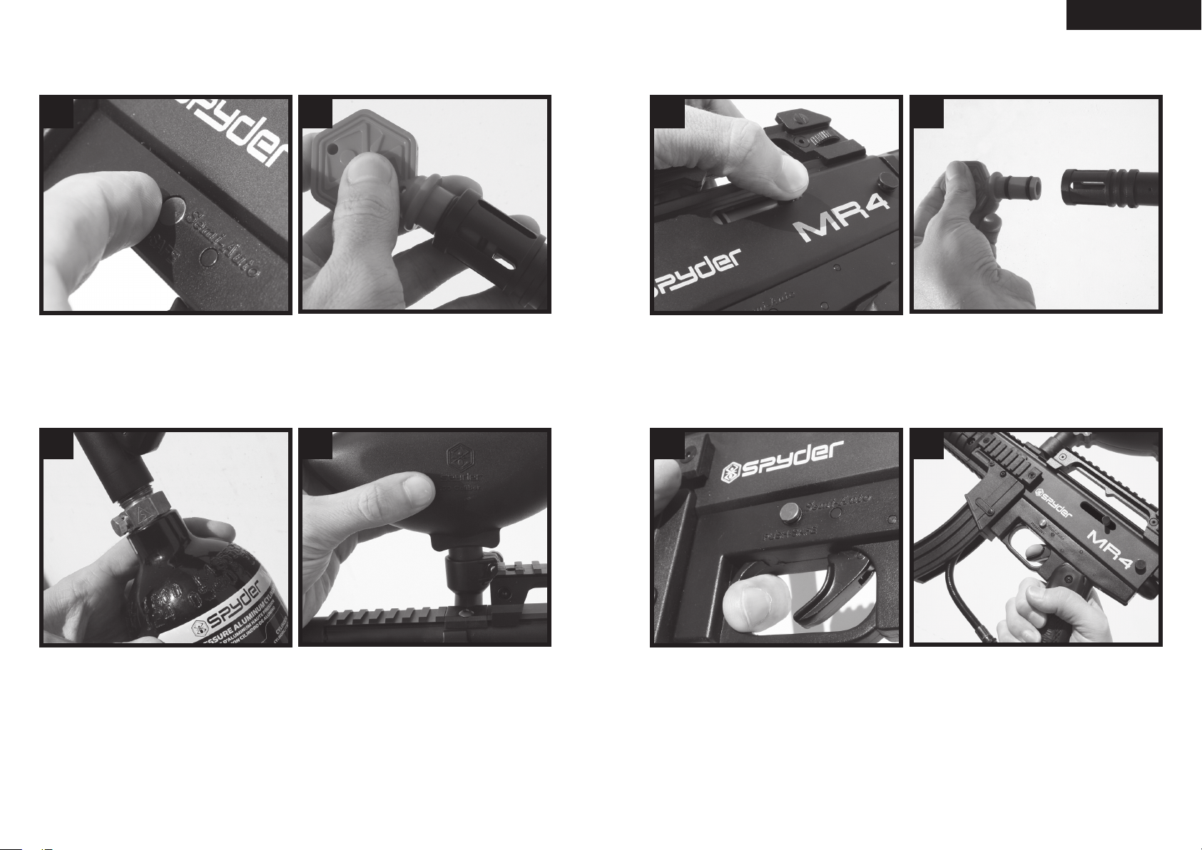
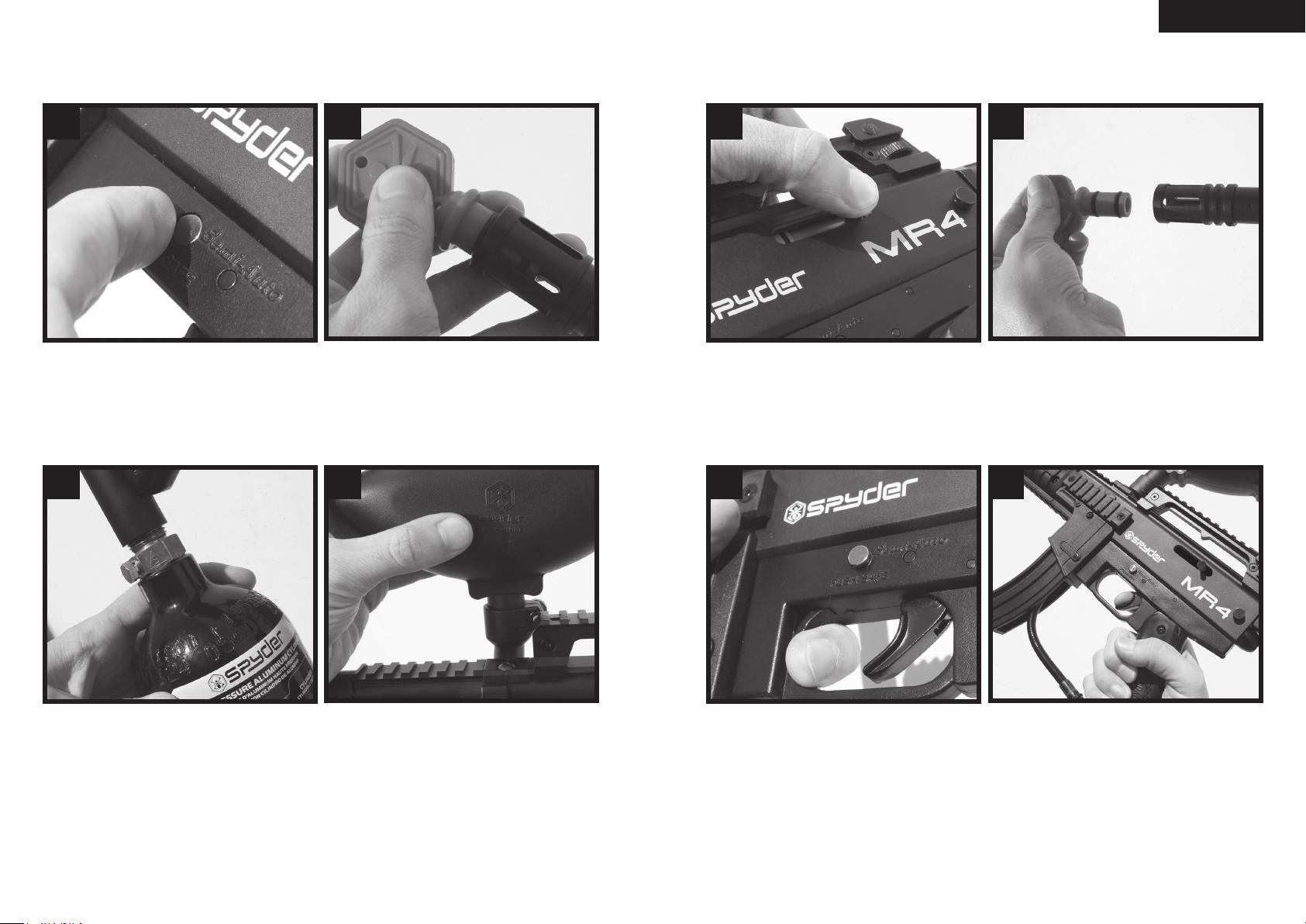
8 STEPS TO START AND PLAY
IMPORTANT: Please read the Safety and Operation Guidelines before you start the 8 quick steps to Start and Play.
English
1. 2.
Make sure the safety is ON Insert the barrel blocking devi ce
3. 4.
5. 6.
Pu t on your paintball goggles and
cock back the marke r
7. 8.
Remove the barre l blocking device
Install a CO2/Compressed air tank Install a paintball loader and add
pa intballs in the loader
3 4
Unlock the safety Ready to play fire
IMPORTANT: Make sure the Marker is in the SAFE MODE and the barrel blocking device is on the Marker’s barrel
after PLAY.
Page 5
English
CO2 / COMPRESSED AIR TAN K WARNINGS
SAFE
DANGER
The CO2 or Compressed Air Tank can y off with enough force to cause serious
injury or death if the Valve unscrews from the cylinder head. LOOK at the Valve
when removing the cylinder from the marker. Be sure that the valve is turning
with the cylinder rather than remaining stationary with the marker. STOP if the
Valve starts to unscrew from the cylinder. If in doubt, screw the cylinder back
onto the marker and contact a trained person for repair.
WARNING:UNSAFE
CO2 / COMPRESSED AIR TAN K WARNINGS
All v alve s mu st o nly be ins talled or removed by a qu alifie d ai rsmith .
•
See C O2 / Com pres sed Air ta nk l abel s fo r re test d ates . Cy lind er tan ks m ust be retest ed
•
perio dicall y.
Improper use, fil ling , storage or dispos al o f al l air cyli nders may resu lt i n death, person al i njur y
•
and/or prope rty da mage.
Alway s ke ep c ylinde rs o ut o f re ach from ch ildren or any i nexperi ence d pers on(s).
•
Only prop erly tra ined perso nnel in accordan ce w ith CGA P amph lets P.1 and G-6.3 mu st fil l al l air
•
cylin ders. Pamp hlet s ar e av aila ble fro m the Comp ressed Gas As soci ation or w ww.CG ANET.c om.
Nev er a lter the c ylin der in any way .
•
DO NOT expo se pressu rize d cyli nder s to tempe ratures in excess of 1 30˚F ( 54˚C ).
•
Cylin ders hea ted to an excess of 2 50˚F ( 121˚ C) mus t be cond emned or requ alifie d in acc orda nce
•
with test d efin ed i n CFR-49.
The v alve sho uld NEVER be d etache d from the canist er. Please seek imme diate assi stan ce f rom a
•
tra ined a irsm ith sh ould thi s occur.
Any t ank pa cked wi th the produc t is i nten ded for paintball use o nly.
•
Confi rm that there is an attach ed u reth ane O-ring on the CO2 / Com pres sed Air ta nk v alve be fore
•
attac hing t he t ank to the mar ker. The tan k wi ll leak a ir as soon as it is secu red to the mar ker, i f the
O-rin g is m issi ng f rom the valve.
A ure than e O- ring i s hi ghly reco mmen ded befo re a ttachi ng a ny a ir sup ply to the mar ker.
•
NEVER over p ress urize a C O2 / Com pres sed Air cy lind er.
•
Avoid any dire ct s kin expos ure to t he esc apin g ga s, whe n in stalli ng o r re movi ng a ny a ir sup ply.
•
Nev er expo se cyl inde rs to corro sive mat erials or clea n with any cau stic c lean ers.
•
RE MOVI NG A CO2 / COMPRESSED AIR TANK
Firmly unscrew the CO2 / Compressed Air Tank by turning the tank counter-clockwise until it comes out of the C/A
Adapter. HELPFUL TIP: After ring the marker, you should ALWAYS remove the CO2 / Compressed Air Tank before
storing. When the tank is being removed, excess air will release from the C/A Adapter. CAUTION: Never expose any
skin to the C/A Adapters bleed hole when removing the tank. This is to avoid the risk of getting skin burn from the
escaping GAS.
IMPORTANT: You should never need to use any hand tool to detach a CO2 / Compressed Air Tank from the C/A
Adapter. If you cannot remove a tank by hand please see a certied airsmith for assistance.
PR OPER USE OF YOUR BARREL BLO CKING DEVICE
A Barrel Blocking Device or “BBD” is an essential part of your paintball safety equipment. The Barrel Blocking Device
is designed to stop a paintball from exiting a paintball marker accidentally. Improper use of the Barrel Blocking Device
will render this device useless.
BARREL SOCK/BAG TYPE DEVICE
Place the bag/sock part of the Barrel Blocking Device over the end of your barrel and wrap the elastic cord around the
back end of your marker.
Adjust the length of the elastic cord to make sure your Barrel Blocking Device ts securely over your markers barrel.
NOTE: If the elastic cord is too long you can tie a couple of knots around the cord to shorten its length.
BARREL PLUG TYPE DEVICE
Insert the barrel plug securely into the end of your markers barrel before proceeding to load paintballs and screwing in
your tank to your marker.
The barrel plug should t rmly into the barrel with a signicant amount of resistance. NOTE: The barrel plug should
not be easy to remove and always inspect the O-rings to make sure they are not worn or cut.
Remove the Barrel Blocking Device only when you are getting ready to begin play or have been instructed to do so by
a eld safety ofcial.
Always keep your Barrel Blocking Device on your marker after you have nished playing. Keep it in place
even after you have emptied all paintballs and removed your air tank from your paintball marker.
WARNING:
Inspect your Barrel Block Device regularly for wear and any tear if it is worn, replace it immediately.
•
Always have your Barrel Blocking Device in place on your markers barrel to insure safety and prevent accidents
•
that may cause permanent injury or even death.
IN STALL ING / REMOVI NG A PAINTBAL L LOADER
Attach an electronic or gravity paintball loader to the
Markers Feed Neck and tighten the set screw. Only use
.68 caliber paintballs through the loader.
Loosen the Feed Neck set screw and remove the
electronic or gravity paintball loader. When removing
the loader make sure to remove all paintballs. CAUTION:
There may be paintballs in the Markers breach; take a
couple of shots in a safe direction to make sure the barrel
and Receiver are empty.
IN STALL ING A CO2 / COMPRESSED AIR TANK
Firmly screw the CO2 / Compressed Air Tank clockwise into the markers C/A Adapter. HELPFUL TIP: Before installing
a CO2 / Compressed Air Tank, make sure that the tank is full and that it has a urethane bottle o-ring on the top of the
valve to prevent air leaks.
IMPORTANT: You should never need to use any hand tool to attach a CO2 / Compressed Air Tank to the C/A Adapter.
5
6
Page 6
English
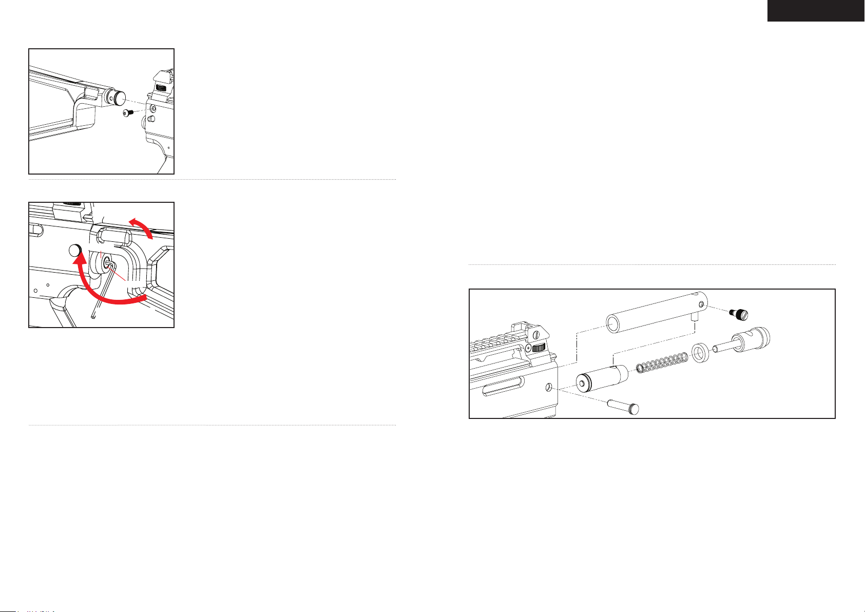
IN STALL ING / REMOVI NG A SHOULDER STOCK
Place the Shoulder Stock in the top breach of the Receiver behind
the Venturi Bolt. Once the Shoulder Stock is in place secure the
Stock with the set screw provided, then tighten with the Allen
wrench.
Loosen the set screw on the right side of the Receiver with the
Allen wrench. Then remove the Shoulder Stock out the top breach
of the Receiver. HELPFUL TIP: The Shoulder Stock must be
removed if intended to clean the marker. (SEE DISASSEMBLE/
REASSEMBLE AND CLEANING OR REAR INTERNALS).}
VE LOCITY ADJ USTMENT INCRE ASE / DECREASE
Decrease Velocity
ST P046
VTA0 46
Increase Velocity
WARNING
•
The recommended Velocity speed should be no greater than 300 fps. Not doing so can cause serious injury if
the Velocity is dangerously high.
• Paintball markers are not intended to shoot any person less than 30 feet.
• Never point a loaded marker at any person who is not wearing the proper face protection.
• Never at any point should you look down the barrel, whether the marker is loaded or not.
• Using a paintball marker outside a non designated paintball eld can be illegal, and is subject to law enforcement
penalties if property damage is caused by the user.
To INCREASE your velocity (fps) using the Allen wrench, turn the
Velocity Adjuster/Spring Guide clockwise.
To DECREASE your velocity (fps) using the Allen wrench, turn the
Velocity Adjuster/Spring Guide counter-clockwise. HELPFUL TIP:
Allen wrench is provided in the spare parts kit. NOTE: The Velocity
Adjuster/Spring Guide doesn’t remove from the rear of the Striker
Plug.
NOTE: The velocity of this paintball Marker ranges from
approximately 220 - 300 feet per second (fps). Velocities
will uctuate or vary due to paintball size, climate condition,
altitude, type of air source and variance in spring tension from
manufacturing.
A JAMMED PAIN TBALL
In the event of a paintball break and the Venturi Bolt jams, follow these steps to help un-jam the Marker. The Markers
breach is located where the barrel starts to thread in the Receiver and underneath the Markers feed neck. Before
attempting to un-jam the Venturi Bolt you should always have your Goggles or Safety Glasses on. Make sure the
Marker is in the SAFE MODE position before attempting to un-jam the Venturi Bolt. Remove the CO2/Compressed
Air Tank before attempting to un-jam the Marker. Remove all paintballs and the loader from the feed neck. Have the
barrel removed from the Receiver to allow the paintball(s) to exit. With enough force on the Cocking Knob, pull back
to release the Venturi Bolt from the jammed position. Another method is to use a “Straight Shot Squeegee” or the
end of a wood dowel rod; push against the face of the Venturi Bolt with enough force to release the jammed Bolt.
Always clean the paint from the breach and barrel to enhance the performance of your Marker.
DANGER: Never look down the barrel of the Marker when loaded or unloaded. Remove the attached CO2/
Compressed Air Tank before attempting to un-jam the Venturi Bolt. NOTE: Never use a metal rod or screwdriver as a
tool to push on the Venturi Bolt, anything metal will scratch and damage the inside of the Marker.
7
HOW TO CLEAN THE MARKER
DANGER: Do not look down the Marker barrel. Always wear goggles specically designed for paintball use while
working on your paintball Marker.
IMPORTANT: Always have the Marker on SAFE MODE before disassembly. Remove all paintballs and air source
from the Marker before performing any maintenance.
HELPFUL TIP: Follow these steps to help clean/remove Marker parts should in the event of a paintball break.
SQ UEEGEE CLEANING OF THE BARREL AND BREACH (no t i ncl uded )
Using a Stick Squeegee (not included)
If the Venturi Bolt is in the un-cocked position you need to re-cock the Marker. Slide a stick squeegee down the
barrel until it reaches the Markers breach. Then remove the stick squeegee out of the barrel. This should wipe clean
any paint residue that could have broken inside the Marker. HELPFUL TIP: Make sure the Markers breach is clean
and clear of any paintball shell fragments or dirt. Repeat this step if the paint residue did not wipe clean after the
rst attempt.
Using a Cable Swab Squeegee (not included)
Twist off the barrel and slide a cable swab squeegee from the threaded end so the swab is the last portion of the
squeegee out of the barrel tip. Grab hold the tail of the cable squeegee and pull. This should wipe clean any paint
residue that could have broken in the barrel. HELPFUL TIP: Make sure the Markers breach is clean and clear of any
paintball shell fragments or dirt. Repeat this step if the paint residue did not wipe clean after the rst attempt.
DI SASSEMBLE/REASSEMBLE AND CLEANING OF REAR INTERNALS
Part Names and Numbers describe in this section:
Top Cocking Knob (#STK011)
Venturi Bolt (#VBT046)
Striker Bolt (#STB002)
Striker Spring (#SPR023)
HELPFUL TIP: The Shoulder Stock must be removed from the Marker before disassembling the marker internals.
Disassemble Of Rear Internals
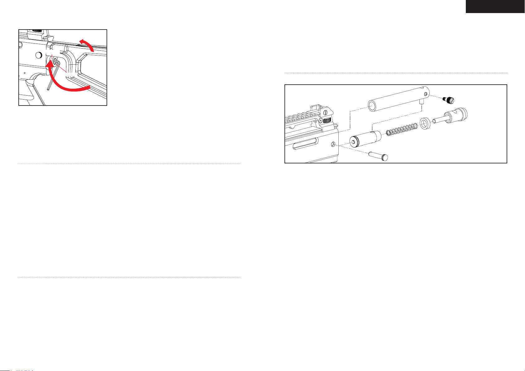
STEP 1 Pull out the Disconnect Pin from the Receiver. HELPFUL TIP: Remove the Striker Plug while the marker in
the un-cocked position this will prevent the internals from springing out because the Striker Spring is compressed.
STEP 2 Remove the Striker Plug with the Striker Spring and Striker Buffer out the back of the Receiver.
STEP 3 Slide the Cocking Knob with the Venturi Bolt towards the rear of the Receiver and unscrew the Cocking
Knob from the Venturi Bolt.
STEP 4 Tilt the back of the marker into your hands ready catch the Venturi Bolt and Striker Bolt from the back
of the Receiver. HELPFUL TIP: When the internals are removed it would be wise to clean any dirt or paint from
RE C046
ST B002
VB T046
SP R023
RP N016
Quick Disconnect Pin (#RPN016)
Striker Buffer (#STF001)
Striker Plug (#STP046)
Velocity Adjuster (#VTA046)
Receiver (#REC046)
ST F001
ST K011
VTA0 46
ST P046
8
Page 7
English
the inside of the Receiver with a squeegee and wipe the Venturi Bolt clean with a rag or paper towel. Apply some
paintball gun oil on Striker O-ring periodically. IMPORTANT: It is not necessary to disassemble the rear internals for
basic maintenance unless the Striker O-ring needs to be replaced.
Reassembly Rear Internals
STEP 1 Insert the Venturi Bolt and the Striker Bolt together. The open face of the Venturi Bolt and Striker Bolt o-
ring must be facing forward and should be inserted rst into the Receiver.
STEP 2 Apply thumb pressure on the Striker Bolt or Venturi Bolt, pull the trigger to allow the Striker and Venturi
Bolt to rest halfway inside the Receiver. Screw on the Cocking Knob onto the Venturi Bolt and while push on the
Cocking Knob forward, pull the trigger again. The Venturi Bolt and Striker Bolt are now in its fully rested position.
STEP 3 Place the Striker Buffer behind the Striker Bolt and insert the Striker Spring with the Striker Plug back into
the Receiver.
STEP 4 Insert the Disconnect Pin to secure the Striker Plug in place. WARNING: Before/after use of the Marker,
make sure to fasten all screws. Screws may become loose due to vibration. Loose screws can be dangerous and
cause injury.
To assure that the Marker is assembled properly, follow the schematic drawing or position parts in order during
disassembly. Parts assembled backwards or improper parts installed will/can cause the Marker to malfunction.
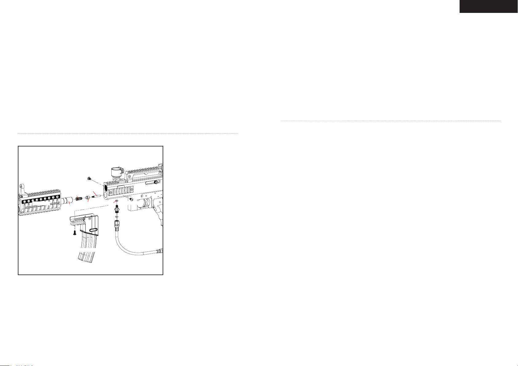
CU P SEAL REMOVAL
Part Names and Numbers
describe in this section:
Disconnect Hose (#HSE013)
Magazine Foregrip Screw (#SCR046)
Center Magazine Foregrip Screw
(#SCR042)
Magazine Style Foregrip (#FRG046)
Reservoir Plug Male Adapter Hose
Fitting (#HSF011)
Vertical O-ring (#ORG026)
Front Barrel Shroud (#FRG044)
Reservoir Plug Shaft (#LPC046)
Valve Spring (#SPR022)
Cup Seal (#ITP023)
Valve Pin (#ITP024)
Plastic Washer (#HSF004)
Receiver (#REC057)
FR G044
SP R022
LP C046
SC R042
SC R046
IT P024
IT P023
FR G046
OR G026
HS F011
RE C046
SC R046
HS F004
HS E013
ST EP BY STE P CUP SEAL ACCESS
HELPFUL TIP: Do not rush or skip any of the steps for proper disassembly of the marker. Remove the barrel before
starting.
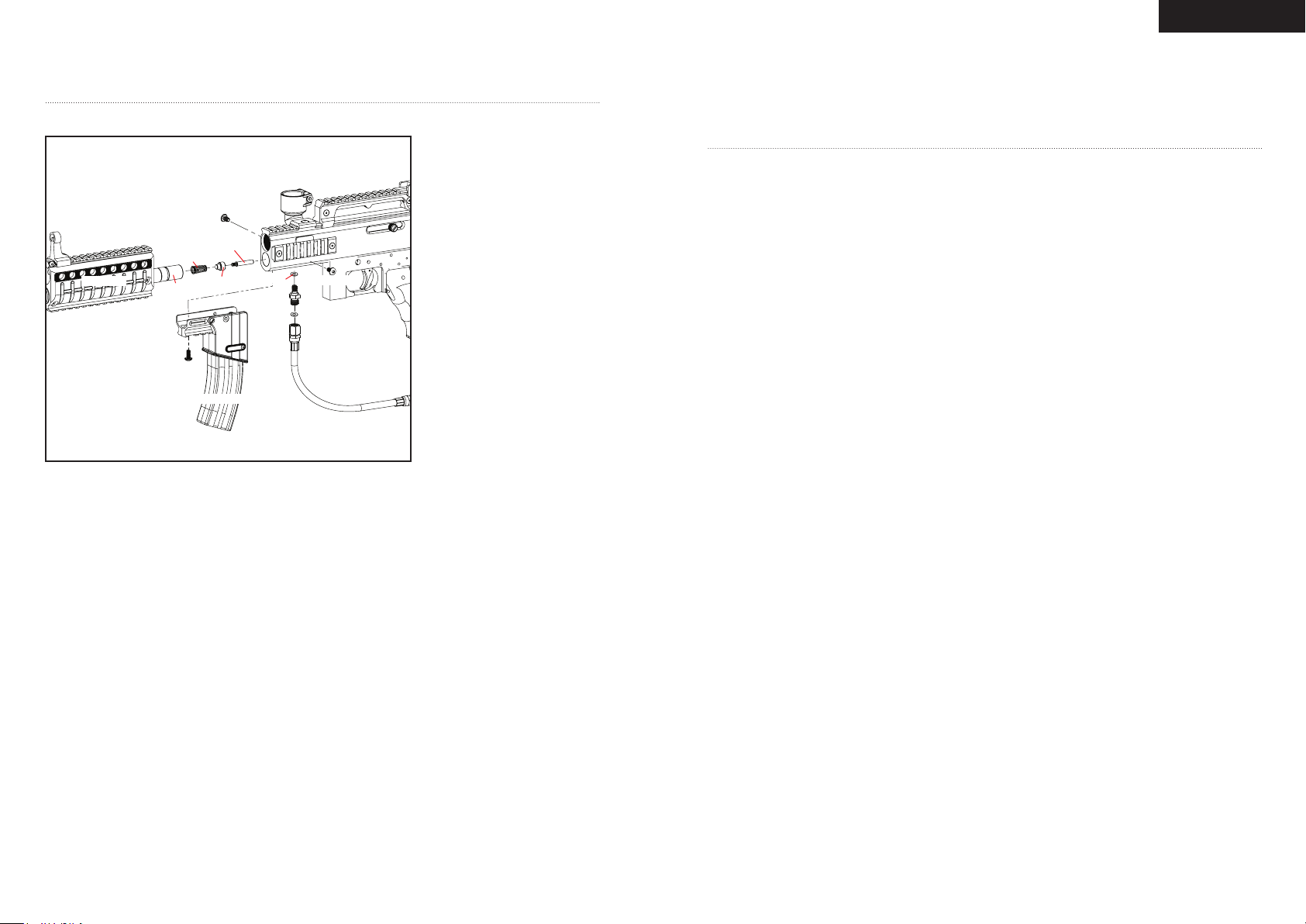
STEP 1 Using a 1/2 inch/13 mm open end or an adjustable wrench to loosen the swivel end of the Hose. NOTE: A
Plastic Washer is inside the female swivel end of the Hose. Make sure you do not lose this part.
STEP 2 Three screws hold the Magazine Style Foregrip in place. One screw is located in front of the Foregrip at
the center of the mounting rail underneath the Receiver. The other two screws are on either side of the Magazine
Foregrip. Unscrew both and remove the Magazine Style Foregrip.
STEP 3 Using an open end or adjustable wrench, unscrew the Reservoir Plug Male Adapter Hose Fitting from the
Reservoir Plug Shaft. This will allow for the removal of the Front Barrel Shroud with the Reservoir Plug Shaft. The
Valve Spring with the Cup Seal and Valve Pin assembly will now be accessible. NOTE: In some instances the Valve
Spring, Cup Seal and Valve Pin assembly may not come out attached with the Reservoir Plug Shaft. All you need to
9
do is tilt the front of the marker down with your hand over the front and the Valve Pin assembly should slide out.
STEP 4 Remove the Valve Spring from the Cup Seal. Unscrew the Cup Seal from the Valve Pin and replace with a
new Cup Seal. NOTE: A spare Cup Seal is provided in the spare parts kit.
STEP 5 Make sure the new Cup Seal is screwed on to the Valve Pin securely and place the Valve Spring on the Cup
Seal. The assembly should be able to hold together as a complete unit.
STEP 6 Place the Valve Pin assembly inside the Receiver and make sure the Valve Pin is seated properly and
centered in the Valve. Check visually by looking down into the Receiver. The assembly should be straight and not
rest at angle or skewed.
STEP 7 Insert the Reservoir Plug Shaft over the Valve Spring assembly and line up the Reservoir Plug Shaft hole
with the Reservoir Plug Male Adapter Hose Fitting hole thru the Receiver.
STEP 8 Screw on the Reservoir Plug Male Adapter Hose Fitting into the Valve Reservoir Plug securely but not
over tightened. NOTE: Make sure to have the O-ring attached to the Reservoir Plug Male Adapter Hose Fitting
before tightening to the Receiver.
STEP 9 Place the Magazine Style Foregrip over the Hose and tighten the 3 screw back onto the Receiver.
STEP 10 Reattach the swivel end Hose tting to the Male to Male tting and tighten with a wrench.
IMPORTANT: Always make sure all air sources have been removed from your marker and any residual air has been
vented out completely before servicing your marker. NOTE: Service or replacement of the Cup Seal should only be
done if a leak is present and can be heard from the breach after the removal of the Venturi Bolt.
TR OUBLESHOOTING
Dealing with a Paintball Breakage
1. If the weather temperature is below 59°F (15°C) or above 86°F (30°C) paintballs can become brittle and not
hold up to the Markers velocity and outside temperature. Paintballs have a shelf life and can become too fragile
for use. Paintballs can take a different shape in time so would be wise to size the paintball with your barrel. Dirt or
broken paint shell fragments in the barrel can cause the Marker to have re-cocking issues. Using a squeegee thru the
upper portion of the Receiver will remove most of the dirt or broken shell fragments.
2. If the loader has double fed a paintball in the barrel/breach and the Marker was red. This can break paint out of
the barrel.
3. If you over shoot the paintball loader and in middle travel have wedged a paintball in the breach this could cause
a paintball breakage.
4. Velocity adjustment is too high and needs to be lowered to proper velocity (fps) speed.
Recocking Rel ated Issues
1. Need lubrication on the Striker O-ring. (SEE DISASSEMBLE/REASSEMBLE AND CLEANING OF REAR
INTERNALS).
2. Striker O-ring is damaged or missing. Replace with a new Kingman approved Striker O-ring. NOTE: The Striker
O-ring can not be substituted with another type of o-ring.
3. The pressure in the tank is too low and possibly needs to be relled.
4. Dirt or broken paint shell fragments in the Receiver can cause the Marker to have recocking issues. Using a
squeegee thru the upper portion of the Receiver will remove most of the dirt or broken shell fragments. Should this
issue continue, remove the Markers internals for complete cleaning. (SEE DISASSEMBLE/REASSEMBLE AND
CLEANING OR REAR INTERNALS).
Dealing With An Air Lea k
Down The Barrel Or Out Of The Trigger Frame
1. Cup seal is bad and needs to be replaced. (SEE CUP SEAL REMOVAL GUIDE)
2. The Valve Body lip is nicked or scratched and needs to be replaced. NOTE: Never remove the Valve Body unless
specic repairs are needed.
3. Air leaking through the Receiver and out of the Trigger Frame. The back o-ring on the Valve Body is damaged
and needs to be replaced.
Ai r Leak Fro m The Hose Line
1. If air is leaking from the opposite ends of the hose ttings will need to retighten to snug.
2. The female end of the hose must have a Plastic Washer installed inside the Hose collar and be tightened
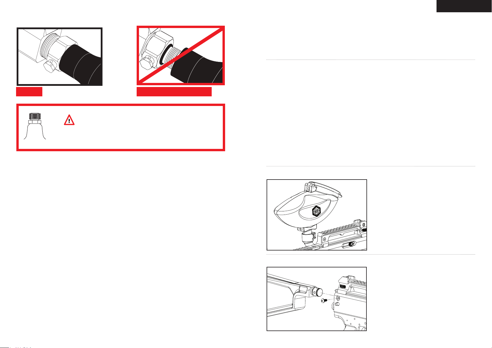
properly. IMPORTANT: The Hose line supplied has metric female ends. This will not install into American 1/8” (NPT)
threaded ttings. If installed incorrectly, it is possible to damage the attachment ttings and hose line.
3. The o-ring on the top of the foregrip has a torn o-ring or needs to be replaced. HELPFUL TIP: You can use a
urethane bottle o-ring for replacement if not able to replace with a stock o-ring.
10
Page 8
English
MR 4™ PAR TS LIST
1
AS A057 C/A Ada pter (ma tte blac k)
2
BAR 001 Sp yder Bar rel Plug
3
BAR 046 1 PCS Barre l 1 2” (m att e bl ack)
4
BL S035 Ball Sto pper
5
FN D046 C lamp ing Feed Nec k w/ Nut & Sc rew
6
FR G002 Tacti cal Shou lde r St ock
7
FR G043 Sh roud Rin g Si ght
8
FR G044 F ront Barr el S hrou d
9
FR G046 Mag azin e St yle Fore grip
10
GR P008 Wra p Aro und Gri p Cov er ( bla ck)
11
HS E013 Di scon nect Hos e (f emal e x fema le) 8 .25”
12
HS F004 P last ic Was her
13
HS F006 Mal e to Mal e Ad apte r (m et x me t)
14
HS F011 Res ervo ir P lug Mal e Ada pte r Ho se F itti ng
15
IT P015 C /A Adap ter Scre w Nu t
16
IT P023 C up S eal
17
IT P024 Valv e Pi n
18
IT P025 Va lve Body
19
LP C046 Re serv oir Plug Sha ft ( bla ck)
20
OR G001 St rike r O- ring #14. 3 1.7 60 pu
21
OR G002 O- ring #15 80
22
OR G003 Ba rrel O-r ing #22 1.5 80
23
OR G004 O -rin g #1 1 80
24
OR G025 Ve loci ty O -rin g # 10 8 0
25
OR G026 Ver tica l O- ring #0 07 1 .8 8 0
*
PAK0 12 Sp are P arts Ki t
27
RE C046 M R4™ Rece iver (mat te blac k)
28
RP N004 Trig ger Roll Pin (la rge)
29
RP N005 S ear Roll Pin (me d)
30
RP N006 Se cond ary Roll Pin (sm all)
31
RP N016 Qu ick Dis conn ect Pin
32
RP N017 Bol t Pi n
33
SA B001 S afet y Bu tton
34
SC R007 M8 x 10 Val ve B ody Scre w (A )
35
SC R010 M5 x 8. 5 Sc rew (A)
36
SC R016 M5 x 1 2 Sc rew (ASH )
37
SC R017 M5 x 12 Scr ew ( ABH)
38
SC R024 M 5 x 25 C/A Ad apte r Sc rew (A)
39
SC R028 M5 x 1 0 Sc rew (A)
40
SC R029 M4 x 6 Scr ew ( A)
41
SC R032 M 4 x 6 Sc rew (A)
42
SC R036 M5 x 8 Fee d Ne ck S crew (A)
43
SC R037 M4 x 1 2 Si ght Rail Fla t Sc rew (A)
44
SC R040 M #8 Fe ed Neck Scre w w/ Nut (b lack )
45
SC R041 M3 x 8 Gri p Sc rew (+)
46
SC R042 M5 x 22 Center Magazine Foregrip Screw (A)
47
SC R044 M4 x 4 Sh roud Rin g Si ght Scre w
48
SC R045 M4 x 14 Shr oud Scre w w/ Nut
49
SC R046 M 4 x 7 Ma gazi ne S hou rd S crew (A)
50
SE R002 Se ar ( semi )
51
SP R008 S ear Spri ng (semi )
52
SP R011 Trigg er S pri ng (s emi )
53
SP R022 Val ve S prin g
54
SP R023 S trik er S prin g
55
ST B002 S trike r B olt
56
ST F001 St riker Bu ffer
57
ST K011 S ide Cock ing Kno b
58
ST K012 S ight Rai l Se t (L eft & Ri ght)
59
ST K014 C ocki ng K nob Cove r
60
ST K015 S ight Rai l Si de Mount
61
ST P046 S trik er P lug (mat te b lack )
62
TR F014 Po lyme r MR 4™ Trig ger Fram e
63
TR S009 Si ngl e Trig ger (sem i)
64
VB T046 Ven turi Bol t w/ Bolt Pin
65
VTA0 46 Velocity Adjuster & Spring Guide (matte black)
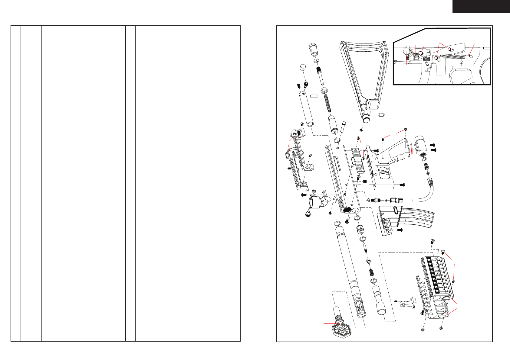
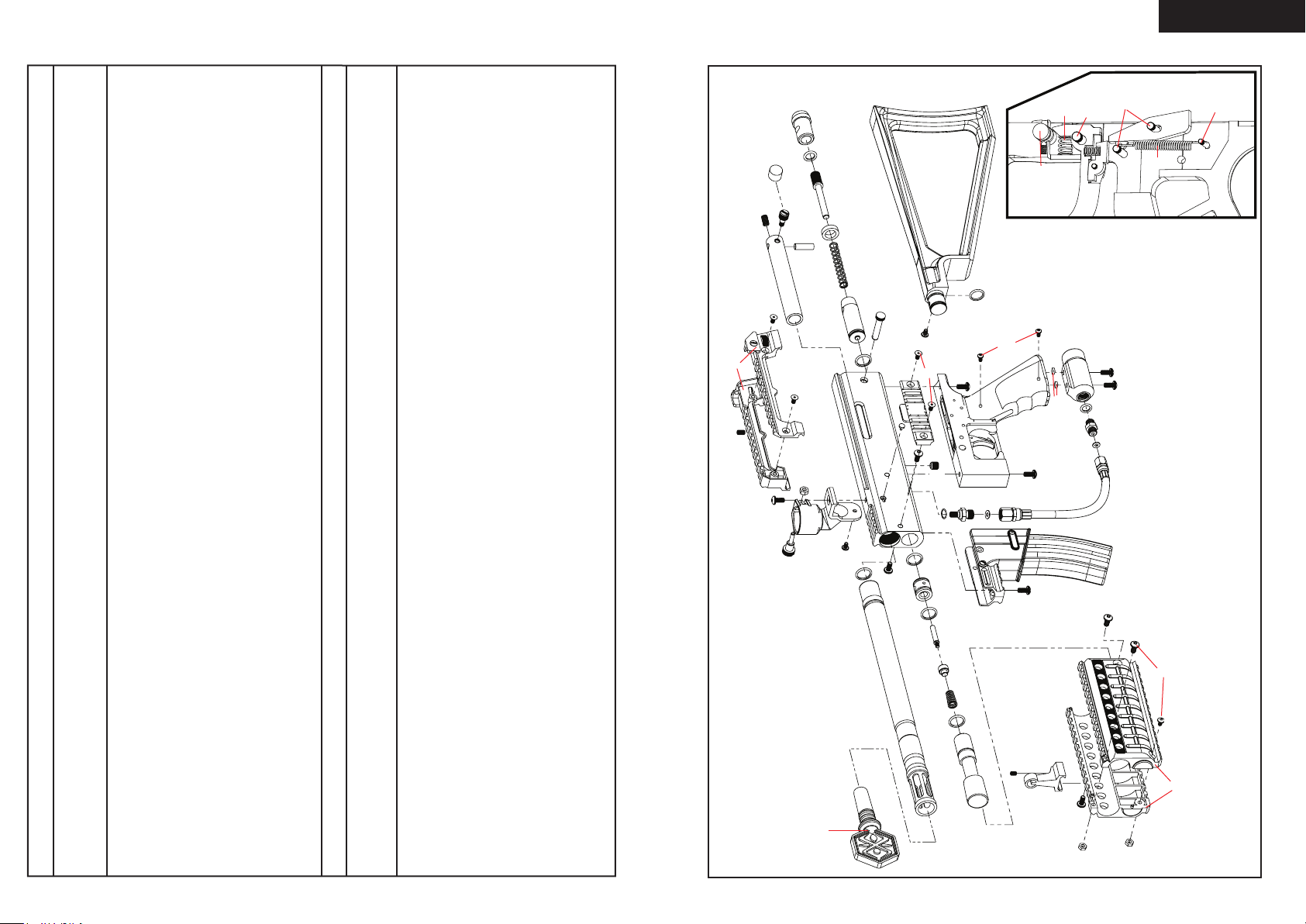
MR 4™ SCHEMATI CS
61
24
59
65
40
57
64
43
58
35
42
32
43
44
56
54
55
5
41
22
2
20
2
31
49
50
52
33
6
21
36
43
60
4
49
34
25
21
18
21
17
16
3
53
21
19
37
14
37
45
15
37
12
9
46
47
7
39
29
28
51
1
38
23
13
12
11
39
48
30
8
11
* Item Not Pictured (+) Cross-head Screw (A) Allen-head Screw
12
Page 9
WARRANTY STATEMENT
Kingm an warrants the orig inal reta il purcha ser that t his Marker is free from de fect s in m ater ial an d
workm anship und er n orma l us e and serv ice for a peri od o f (1 ) ye ar from the origi nal date of pu rcha se.
Kingm an agrees to repa ir or replace (at it s di scre tion ) an y pr oduc t with in a reason able p erio d of
time. Th is warranty does not cover o -rin gs, cu p se als, scratche s, n icks, normal wear and t ear of
parts , any modi fica tions, normal fad ing of ano dizi ng and dam age ca used by drop ping o r hi ttin g of
this prod uct. This warranty s hall n ot a pply if it is shown by a Kin gman Techni cian tha t the cons umer
cause d the defe ct o r ma lfunct ion becaus e of mis use. Thi s warra nty only covers orig inal fact ory
parts . Any modi fica tions or t amperi ng o f or iginal fac tory par ts wil l VOID warrant y an d li abilit ies from
Kingm an. An y da mage cause d by water wil l no t be covered und er w arranty . Warranty repa ir c an o nly
be co nduc ted by Kin gman Tec hnic ian or Kin gman Aut horized Techni cian . Fo r wa rrant y to b e ef fect ive,
consu mer must retu rn t he enc lose d warra nty regi stratio n card fi lled o ut, alon g with a c opy of the
purch ase receipt , with in ( 15) da ys o f th e orig inal purchase dat e. T his warrant y is not t ransferabl e
(pain tbal l Ma rker s ar e no n-re fund able). This warran ty w ill NOT cover pick u p, s hipp ing, delivery , and/or
house calls . If produc t need s re pair, consu mer pl ease pac kage it ca refully and s end togeth er w ith your
name, ad dres s, pho ne n umbe r and a br ief de scri ptio n of t he m alfunc tion to:
KINGM AN GRO UP
Att n: Tech D epartm ent
140 10 L ive Oak Avenu e
Baldw in Park, CA 9170 6 U.S.A .
www.k ingm an.c om
» Warra nty Regi stra tion is al so a vail able at ww w.s pyde r.tv
FOR T ECHN ICAL S UPPO RT
Our Techni cal Suppor t De partme nt i s op en M onda y through Friday , fr om 8 am to 5 p m (P ST), a nd m ay
be reach ed at Tel: (626) 4 30-2 300 Fax: (6 26) 851- 8530
Also avai lable at: www. spyd er.tv/tech supp ort
Français
Mar q eue r de P a int b a ll d e Ca l i bre .68
TABLE DES MATIERES
IMPORTANTES CONSIGNES DE SECURITE 17
MISE EN ROUTE 18
8 ÉTAPES POUR COMMENCER À JOUER 19-20
CONSIGNE DE SECURITE SUR LA BOUTEILLE DE CO2/AIR COMPRIME 21
INSTALATION DE LA BOUTEILLE DE GAZ 21-22
PATEN T PE NDIN G
13
UTILISATION APPROPRIEE DU BOUCHON DE CANON 22
INSTALLATION/RETRAIT D’UN CHARGEUR DE BILLES 22
INSTALLATION/RETRAIT D’UNE CROSSE D’ÉPAULE 22
REGLAGE DE LA VELOCITE, AUGMENTER / DIMINUER 23
BILLE COINCEE DANS LA DESCENTE DE BILLE 23
NETTOYAGE DU MARQUEUR 23-24
DEMONTAGE/REMONTAGE ET NETTOYAGE DES PIECES INTERIEURES ARRIERES 24-25
ACCÈS AU JOINT DE CULASSE ÉTAPE PAR ÉTAPE 25-26
DÉPANNAGE 26
LISTE DES PIECES DU MR4™ 27
SCHEMA ECLATE DU MR4™ 28
POLICE DE GARANTIE 29
Page 10

Français
IM PORTANT ES CONSIGNES DE SECURIT
WARNING
Ce lanceur de paintball n’est pas un jouet, il peut provoquer des blessures grave voir la mort.
•
Kingman recommande que le client soit agé d’au moins 18 ans pour acheter ce produit.
•
Lisez le manuel attentivement et les précautions d’emploi de la bouteille d’air avant d’utiliser ce
•
produit.
Toute modication du produit ou de ses pièces d’origines entraînera l’annulation de la garantie
•
ainsi que la responsabilité de Kingman.
Kingman recommande d’utiliser un bouchon de canon quand le lanceur n’est pas utilisé.
•
Pour s’assurer de la vélocité du lanceur kingman recommande fortement d’utiliser un
•
chronographe spécique au paintball disponible dans la plupart des boutiques spécialisées ou
les terrains de paintball.
Avant et après l’utilisation du lanceur, vériez que toutes les vis sont bien serrées. Les vis
•
peuvent se dévisser à cause vibrations. Une vis mal serrée peut être dangereuse et pourrait
causer des blessures.
Kingman recommande fortement que toute personne utilisant Ce produit ou a la portée de ce
•
produit pendant son utilisation doit porter un masque de protection intégrale qui protège les
yeux et le visage conçu spéciquement pour la pratique du paintball. Il est également primordial
de porter cette protection non seulement pendant le jeu mais aussi pendant la maintenance, la
vérication du lanceur et même pendant du tir sur cible.
Kingman rappel aux usagers qu’il est votre responsabilité de protéger vos yeux et votre visage
•
tout le temps, et ne sera pas tenu responsable d’accident par négligence en ne portant pas les
protections adéquat.
Ne tirez jamais ou ne visez jamais une personne qui ne porte pas les protections adéquates au
•
paintball et qui ne se trouve pas sur un terrain conçu à la pratique du sport.
N’enlevez PAS le bout orange. Ceci permet d’identier que le marqueur de paintball N’est PAS
•
une arme à feu. Transportez toujours le marqueur dans un étui ou un sac, an d’éviter toute
mauvaise identication.
Considérez toujours votre lanceur comme si il était chargé et armé.
•
Ne regardez jamais dans le canon que le lanceur soit chargé ou déchargé.
•
Toujours garder son lanceur éteint ou sur le mode “safe” jusqu’a son utilisation.
•
Toujours démonter la source de gaz du lanceur avant tout démontage.
•
Tirez exclusivement des billes de paintball de calibre 0.68 cal avec ce lanceur.
•
Assurez vous toujours que la culasse soit en position désarmée quand vous n’utilisez pas le
•
lanceur.
Utiliser un lanceur de paintball en dehors d’une zone faite pour le paintball peut être illégal, et
•
peut être passible de poursuites si des dégâts ont été causés par son utilisateur.
Transférez le manuel de l’utilisateur au nouveau propriétaire en cas de vente.
•
Visite www.spyder.tv les mises à jour manuelle des utilisateurs.
•
MI SE EN ROUTE
ATTENTION: Toujours garder son lanceur éteint ou sur le mode “safe” jusqu’a son utilisation.
1. Kingman recommande d’avoir le lanceur en position “SAFE” avant l’utilisation. Pour verrouiller la sécurité,
pousser le bouton du coté “PUSH SAFE” de la poignée. Cela enclenchera la sécurité. Pour désengager la
sécurité d’une manière sécurisée, pointer le lanceur dans une direction sans risque et poussez le bouton du coté
“PUSH FIRE” de la poignée.
2. Placer le bouche canon sur le canon par précaution quand le lanceur n’est pas utilisé.
3. Attacher la bouteille de CO2 ou d’air comprimé à l’adaptateur. CONSEIL: Assurez-vous que la bouteille
de CO2 ou d’air comprimé soit remplie avant de la monter au lanceur. Vissez la bouteille dans le sens des
aiguilles d’une montre dans l’adaptateur jusqu’à ce que la valve s’ouvre. Si vous constatez une fuite entre
la valve de la bouteille et l’adaptateur, remplacez les joints toriques uréthane. NOTE: Les joints toriques
uréthane ne sont pas fournis dans le kit de réparation, ces joints ne sont pas faits pour la valve de la bouteille.
IMPORTANT: Vous ne devriez jamais avoir à utiliser des outils pour monter ou démonter la bouteille de CO2 ou
d’air comprimé sur l’adaptateur.
4. Attacher un coude et un chargeur électrique à la descente de bille (non représenté) NOTE: Remplissez le
chargeur uniquement avec des billes de paintball de calibre 0.68 .cal
5. Armement du marqueur. Armement du marqueur. À gauche du récepteur, se trouve un bouton d’armement que
vous devez tirer vers l’arrière jusqu’à ce que la culasse Venturi s’enclenche ATTENTION: Si vous lâchez la
culasse avant qu’elle ne s’enclenche, un coup pourrait partir.
6. Enlever le bouchon de canon. PRECAUTION: Si le bouton de sécurité est enclenché, le lanceur est en mode
« live », appuyer sur la détente déclenchera le tir d’une bille. IMPORTANT: Toujours tester le lanceur dans une
direction sure ou dans une aire de jeu approprié et vous ne devrez que tester les capacités du lanceur.
7. Effectuez un TEST DE VELOCITÉ (fps). Tourner l’ajusteur de vélocité / guide ressort dans le sens des
aiguilles d’une montre augmentera la vélocité (fps). NOTE: Votre marqueur est destiné à être utilisé uniquement
sur un complexe de paintball avec les protections appropriées à la pratique du paintball. IMPORTANT: Kingman
recommande l’utilisation d’un chronographe pour s’assurer que la vélocité du marqueur soit en dessous de 300
pieds par seconde (fps).
8. Le jeu terminé, retirez toutes les billes de paintball du chargeur puis retirez le chargeur de billes de paintball et le
coude vertical du marqueur. ATTENTION: Il est possible qu’une bille de paintball se trouve dans la descente de
billes; appuyez sur la détente à quelques reprises en pointant le marqueur dans une direction sûre pour vous
assurer que le canon et la descente de billes soient vides.
9. Replacez le bouchon de canon / chaussette à canon, sur le canon quand le lanceur n est pas utilisé. Ceci évitera
tout tir accidentel.
10. Kingman recommande de mettre le marqueur en position “SAFE” après utilisation.
11. Dévissez la bouteille de CO2/air comprimé de l’adaptateur C/A du marqueur. Dévissez dans le sens opposé
des aiguilles d’une montre. ATTENTION: Ne jamais exposer une partie du corps non protégée sous le trou
d’évacuation de CO2/air comprimé de l’adaptateur C/A lorsque vous enlevez la bouteille. Ceci peut entraîner
des risques de brûlure venant de l’évacuation du gaz. IMPORTANT: Vous ne devriez jamais avoir besoin de
recourir à l’utilisation d’outils pour détacher la bouteille de CO2/air comprimé.
12. Placez le marqueur dans un sac de paintball ou dans un endroit sûr. CONSEIL PRATIQUE: Due aux vibrations
les vis peuvent se desserrer et se perdre. Assurez-vous de resserrer toutes les vis avant et après utilisation du
marqueur. Il est conseillé de lubrier le marqueur avant et après chaque utilisation, surtout lorsque le marqueur
n’a pas servi pendant un long laps de temps. Ajoutez quelques gouttes d’huile pour marqueur de paintball sur
le joint de marteau. (Voir guide de démontage/ remontage). Avant de ranger le marqueur, assurez vous d’avoir
votre marqueur en position désarmée. Ceci évitera que le ressort principal ne perde sa tension.
IMPORTANT
La vélocité peut varier selon l’altitude et les conditions climatiques
•
• Avant d’utiliser le lanceur il est impératif de procéder à un « test de sécurité de vélocité ». Pour cela utilisez un appareil
appelé « chronographe de vélocité » spécique au paintball disponible dans la plupart des boutiques spécialisées ou les
terrains de paintball. NOTE: ce lanceur est conçu pour être utilisé a une vélocité inférieure a 300 pieds par seconde
(fps). Ce produit ne doit pas être utilisé sur une personne a moins de 25 pieds.
• Ce lanceur de paintball peut contenir après le démontage de la bouteille de CO2 ou d’air comprimé un excédent de gaz
toujours présent dans le lanceur, toujours enlever les billes du lanceur et tirer quelque coups pour vider l’éventuel
excédent de gaz, en s’assurant de le faire prudemment.
• Ne jamais laissé monté une bouteille de CO2 ou d’air comprimé sur le lanceur si ce dernier n’est pas sous surveillance.
17
18
Page 11
8 ÉTAPE S POUR COMMENCER À JOUER
IMPORTANT: Lire les recommandations de sécurité et de fonctionnement avant de suivre les 8 étapes rapides pour
commencer à jouer.
Français
1. 2.
As surez-vou s q ue la sécurité soit
sur ON
3. 4.
Insérez le dispositif de blocage du
ca non
5. 6.
Mettez vo s lunettes de paintball et
armez le marq ueur
Retirez le dispositif de blocage du
ca non
7. 8.
Installez une bouteille de CO2 /
d’a ir comprimé
19
Installez un chargeur de billes et
remplissez-le
Déverrouillez la sécur ité Prêt à jouer et tirer
IMPORTANT: S’assurer que le marqueur est en MODE SÉCURITÉ et que le dispositif de blocage du canon est bien
en place sur le marqueur après avoir JOUÉ.
20
Page 12
Français
CONSIGNE DE SECURITE SUR LA BOUTEILLE DE CO2/AIR COMPRIME
DEMONTER UNE BOUTEILLE DE CO2/AIR COMPRIME
Dévisser la bouteille de CO2 ou d’air comprimé de l’adaptateur en tournant dans le sens inverse des aiguilles d’une
montre. CONSEIL: après l’utilisation vous devriez toujours démonter la source de gaz de votre lanceur. Quand la
bouteille est démontée de l’adaptateur on/off, un excèdent de gaz est purge par le dessous. PRECAUTION: Ne jamais
exposer la peau en dessous de l’adaptateur on/off où se trouve le trou d évacuations lors du démontage. Ceci peut
provoquer des brûlures de la peau au moment de la purge du gaz. IMPORTANT: vous ne devriez jamais avoir à utiliser
des outils pour monter ou démonter la bouteille de CO2 ou d’air comprimé sur l’adaptateur on/off.
UTILISATION APPROPRIEE DU BOUCHON DE CANON
Le bouchon de canon est une partie essentielle à la sécurité de votre équipement .Le bouchon de canon est un outil
servant a empêcher les billes de sortir du canon. Mal utilisé le bouchon de canon ne sert à rien.
BOUCHON DE CANON TYPE “CHAUSSETTE”
SAFE WARNING:UNSAFE
La bouteille de CO2 ou d’air comprimé peut partir avec assez de force pour
causer des blessures graves ou la mort si la valve se détache de la bouteille.
Toujours regarder la valve en devisant la bouteille, en s’assurant que la valve
DANGER
CONSIGNE DE SECURITE SUR LA BOUTEILLE DE CO2/AIR COMPRIME
• Toute valve doit être installée et désinstallée par une personne compétente en pneumatique.
• Reportez vous au label sur la bouteille pour les dates de ré épreuve .Les bouteilles doivent être réprouvé
périodiquement.
• Une utilisation, remplissage, conservation inadaptée a la bouteille peut provoquer la mort, des blessures
ou / et des dégradation au matériel.
• Toujours garder les bouteilles hors de porter des enfants ou de personnes non expérimentées.
• Seulement les personnes ayant suivi un stage de remplissage avec la CGA PamphletsP.1 et G-6.3
sont autorisées à remplir les bouteilles. Les Pamphlets sont disponible au près de l association «
COMPRESSED GAS ASSOCIATION » ou sur le site www.CGANET.com.
• Ne jamais modier la bouteille d’aucune manière que ce soit.
• Ne JAMAIS exposer une bouteille sous pression a une température supérieure a 130F (54C)
• Une bouteille chauffée à une température supérieure a 250F (121C) doit être jetée ou ré éprouvée en
conformité avec le test déni dans le CFR-49
• La valve ne devrait jamais être détachée de la bouteille, demander immédiatement une assistance à une
personne compétente si cela se produit.
• Toute bouteille inclue avec ce produit doit être utilisée exclusivement pour la pratique du paintball et rien
d’autre.
• Vériez que le joint torique uréthane est bien présent sur la valve de la bouteille de CO2 ou d’air
comprimé avant de monter la bouteille sur le lanceur. Si le joint torique est manquant, la bouteille se
mettra à fuire du moment que la bouteille sera attachée au lanceur.
• Il est fortement conseillé d’utiliser exclusivement des joints torique uréthane.
• Ne jamais monter la bouteille de CO2 ou d’air comprimé en surpression.
• Evitez toute exposition directe de la peau au gaz purgé, en montant ou démontant la bouteille du
lanceur.
• Ne jamais exposer la bouteille a des substances corrosives ou produits caustiques
MONTER UNE BOUTEILLE DE CO2/AIR COMPRIME
Visser fermement la bouteille de CO2 ou d’air comprimé dans le sens des aiguilles d’une montre dans l’adaptateurC/A
CONSEIL: toujours vérier que la bouteille de CO2 ou d’air comprimé soit pleine et que le joint uréthane soit présent
sur la valve pour éviter des fuites.
IMPORTANT: vous ne devriez jamais avoir à utiliser des outils pour monter ou démonter la bouteille de CO2 ou d’air
comprimé sur leC/A adaptateur
tourne avec la bouteille et ne reste pas sans bouger contre l’adaptateur on/off.
Arrêter le démontage si la valve commence à se dévisser de la bouteille. Dans
le doute, revisser la bouteille (sens des aiguilles d’une montre) et contactez une
personne compétente pour la réparation.
Placer la chaussette du bouchon de canon par dessus le bout du canon et tirez l’élastique pour l’accrocher a l’arrière
du lanceur,puis ,ajuster l’élastique de manière à ce que la tension soit sufsante pour arrêter une bille sortant du
canon. NOTE: si l’élastique est trop long, vous pouvez faire des nœuds pour raccourcir l’élastique.
BOUCHON DE CANON TYPE “BOUCHON RIGIDE”
Inserez le bouchon de canon au bout de votre canon avant de monter la bouteille de gaz et de mettre des billes dans
votre lanceur. Le bouchon de canon ne doit pas pouvoir s’enlever facilement.
NOTE: veriez toujours que les joints toriques ne soient pas usés ou encore coupé. N’enlevez le bouchon de canon
que quand vous êtes prêt à jouer. Gardez toujours votre bouchon de canon sur votre lanceur après avoir ni de jouer
et gardez-le, même après avoir vidé le lanceur des billes de paintball et démonté la bouteille de gaz de votre lanceur.
ATTENTION
Pensez à inspecter régulièrement votre bouchon de canon, si vous observez une usure, remplacez le immédiatement.
Toujours avoir votre bouchon de canon sur votre lanceur pour prévenir un éventuel accident qui pourrait causer de
blessures grave ou même la mort.
IN STALL ATION / RETRAIT D’UN CHARGEUR DE BILLES
Fixer un chargeur de billes électronique ou à gravité au
distributeur de marqueurs et serrer les vis de pression.
Serrer les deux accessoires pour assurer une bonne
xation. N’utiliser que des billes de calibre 0.68 dans le
chargeur.
Desserrer les vis du distributeur de marqueurs et retirer
le chargeur de billes électronique ou à gravité. Lors du
retrait du chargeur, s’assurer que toutes les billes soient
retirées. ATTENTION : Il peut rester des billes dans le
conducteur du marqueur ; donner quelques coups dans
une direction sans danger pour vérier que le canon et la
culasse sont vides.
IN STALL ATION / RETRAIT D’UNE CROSSE D’ÉPAULE
Placez la crosse d’épaule dans le conducteur supérieur du
récepteur derrière la culasse Venturi. Une fois la crosse
d’épaule en place, bloquez-la avec les vis de pression
fournies, puis serrez celles-ci avec la clé hexagonale.
Desserrez les vis sur le côté droit du récepteur avec la
clé hexagonale. Retirez ensuite la crosse d’épaule du
conducteur supérieur du récepteur. CONSEIL UTILE :
La crosse d‘épaule doit être retirée avant de nettoyer
le marqueur. (VOIR DÉMONTAGE/MONTAGE ET
NETTOYAGE OU PARTIES INTERNES ARRIÈRE).
21 22
Page 13
Français
REGLAGE DE LA VELOCITE, AUGMENTER / DIMINUER
DIMINUER
ST P046
VTA0 46
AUGMENTE
MISE EN GARDE
• La vélocité de ne doit jamais excédée 300 fps, une vélocité plus importante est dangereuse et peu causée de
sérieuses blessures.
• Les lanceurs de paintball ne sont pas fait pour être utilisés contre des personnes a moins de 30 feet.
• Ne jamais pointer le lanceur en direction d’une personne qui ne porte pas une protection faciale adaptée a la
pratique du paintball .
• Ne regardez jamais dans le canon à aucun moment que le lanceur soit chargé ou non.
• Utiliser un lanceur de paintball en dehors d’une zone faite pour le paintball peut être illégal, et peut être passible
de poursuites si des dégâts ont été causés par son utilisateur.
Pour AUGMENTER la vélocité FPS (feet per second = pieds par
seconde) utilisez la clef six pans et tournez la pièce VELOCITY
ADJUSTER/SPRING GUIDE) dans le sens des aiguilles d’une
montre.
Pour DIMINUER la vélocité, tournez dans le sens inverse des
aiguilles d’une montre.
NOTE: la pièce VELOCITY ADJUSTER/SPRING GUIDE ne se
démonte pas par l’arrière du bouchon de la pièce STRIKER PLUG
BI LLE COINCEE DANS LA DESC ENTE DE BILLE
Dans l’éventualité ou une bille serait coincée par la culasse et la bloquerai, suivez cette procédure pour débloquer
la bille. La chambre de la bille est située juste avant le canon en dessous de la descente de bille. Avant d’essayer de
débloquer la bille vous devez porter votre masque de protection. Assurez vous d’avoir mis le lanceur en position off
ou enclenché la sécurité. Démontez la bouteille de CO2 ou d’air comprimé, enlevez le chargeur de billes, et assurez
vous qu’il ne reste plus de billes dans le lanceur. Dévissez le canon du lanceur pour permettre à la bille coincée de
sortir. Tirez avec une force sufsante sur la goupille de réarmement vers l’arrière jusqu’à débloquer la culasse. Si
vous n’arrivez toujours pas par ce moyen à décoincer la culasse, une autre méthode consiste a prendre une tige
de nettoyage droite et rigide ou bien une tige en bois et pousser la culasse vers l’arrière en poussant avec la tige
depuis l’avant du lanceur en faisant attention que la surface en contact avec le devant de la culasse soit plat pour
ne pas endommager la culasse ou l’alésage du corps. Après avoir débloqué la culasse d’une manière ou d’une autre,
nettoyez la chambre de la bille et la culasse si nécessaire pour assurer des performances optimums.
IMPORTANT: ne regardez jamais dans le canon que le lanceur soit chargé ou non.
Toujours démonter la source de gaz avant d’entreprendre le décoinçage de la culasse.
NOTE: Ne jamais utiliser une tige en métal pour pousser la culasse, cela pourrait rayer le corps ou la culasse.
NE TTOYAGE DU MARQUEUR
DANGER : Ne pas regarder dans le canon du marqueur. Toujours porter des lunettes spécialement conçues pour les
marqueurs de paintball, dès que vous manipulez votre marqueur.
IMPORTANT : Toujours mettre le marqueur en MODE SÉCURITÉ avant de le démonter. Retirer toutes les billes et
toute source d’air éventuelle du marqueur avant d’effectuer les tâches de maintenance.
CONSEIL UTILE : Suivre ces étapes pour enlever la bille / nettoyer le marqueur, en cas de rupture de bille.
NE TTOYAGE DU CA NON ET DU CONDUCTEUR AVEC UNE RACL ETTE
Utilisation d’une tige de nettoyage rigide (non fournie)
Si la culasse Venturi est en position non armée, vous devez réarmer le marqueur. Faire glisser la tige rigide vers le
bas du canon jusqu’au conducteur du marqueur. Retirer ensuite la tige du canon. Ceci devrait nettoyer tout résidu
23
de peinture qui aurait pénétré à l’intérieur du marqueur. CONSEIL UTILE : S’assurer que le conducteur du marqueur
est propre, sans fragments de cartouche de bille ni poussière. Répéter cette étape s’il reste encore des résidus de
peinture.
Utilisation d’une tige de nettoyage pourvue d’un coton-tige (non fournie)
Dévisser le canon et faire glisser le coton-tige en partant de l’extrémité letée, an que le bout du coton-tige
atteigne le bout du canon. Saisir le bout de la tige de nettoyage et tirer. Ceci devrait éliminer tout résidu de peinture
qui aurait pénétré à l’intérieur du canon. CONSEIL UTILE : S’assurer que le conducteur du marqueur est propre, sans
fragments de cartouche de bille ni poussière. Répéter cette étape s’il reste encore des résidus de peinture.
DEMONTAGE/REM ONTAGE ET NE TTOYAGE DES PIEC ES INTERIEU RES ARRIERE S
Noms et des numéros de pièces dans cette section:
Top Cocking Knob (#STK011)
Venturi Bolt (#VBT046)
Striker Bolt (#STB002)
Striker Spring (#SPR023)
DEMONTAGE DES PIECES INTERNES ARRIERES
ÉTAPE 1 : Retirez la tige de débranchement du récepteur. CONSEIL UTILE : Enlevez l’obturateur du percuteur
lorsque le marqueur est en position désarmée ; l’obturateur du percuteur étant comprimé, les pièces internes ne
sortiront pas brusquement.
ÉTAPE 2 : Retirer l’obturateur du percuteur, le ressor t du percuteur et le butoir du percuteur de l’arrière du
récepteur.
ÉTAPE 3 : La culasse Venturi étant dirigée vers l’arrière du récepteur, faites glisser le bouton d’armement et
dévissez-le de la culasse.
ÉTAPE 4 : Inclinez l’arrière du marquer dans vos mains pour attraper la culasse Venturi et le verrou du percuteur
situés à l’arrière du récepteur.
CONSEIL: nettoyez l’intérieur du corps a l’aide d’une tige, nettoyez également le marteau et la culasse en
remettant quelque goûtes d’huile sur le joint torique rouge du marteau.
IMPORTANT: il n’ est pas necessaire de demonter les pieces internes pour un entretient normal a moins que vous
deviez changer le joint torique du marteau (striker O-ring).
REMONTAGE DES PIECES INTERNES ARRIERES
ÉTAPE 1 : Introduisez la culasse Venturi et le verrou du percuteur ensemble. La partie ouverte de la culasse Venturi
et du joint torique du verrou du percuteur doit être orientée vers l’avant et insérée en premier dans le récepteur.
ÉTAPE 2 : Avec le pouce, appuyez sur le verrou du percuteur ou la culasse Venturi, tirez la gâchette an de
permettre au percuteur et à la culasse Venturi de rester à mi-chemin dans le récepteur. Vissez le bouton d’armement
sur la culasse Venturi et, tout en le poussant vers l’avant, appuyez à nouveau sur la gâchette. La culasse Venturi et le
verrou du percuteur sont désormais en position désarmée.
ÉTAPE 3 : Mettez le tampon du percuteur derrière le verrou du percuteur, puis introduisez à nouveau le ressort du
percuteur avec l’obturateur du percuteur dans le récepteur.
RE C046
ST B002
VB T046
SP R023
RP N016
Quick Disconnect Pin (#RPN016)
Striker Buffer (#STF001)
Striker Plug (#STP046)
Velocity Adjuster (#VTA046)
Receiver (#REC046)
ST F001
ST K011
VTA0 46
ST P046
24
Page 14
Français
ÉTAPE 4 : Introduisez la tige de débranchement pour bloquer l’obturateur du percuteur en place.
MISE EN GARDE: avant et après l’utilisation, vériez que toutes les vis soient bien serrées, une vis desserrée peut
cause de sérieuses blessures.
ACCÈS AU JOINT DE CULASSE ÉTAPE PAR ÉTAPE
Noms et des numéros de
pièces dans cette section:
Disconnect Hose (#HSE013)
Magazine Foregrip Screw (#SCR046)
SC R046
Center Magazine Foregrip Screw
(#SCR042)
Magazine Style Foregrip (#FRG046)
Reservoir Plug Male Adapter Hose
Fitting (#HSF011)
Verical O-ring (#ORG026)
Front Barrel Shroud (#FRG044)
Reservoir Plug Shaft (#LPC046)
Valve Spring (#SPR022)
FR G044
SP R022
LP C046
IT P024
IT P023
OR G026
HS F011
RE C046
SC R046
HS F004
Cup Seal (#ITP023)
SC R042
FR G046
HS E013
Valve Pin (#ITP024)
Plastic Washer (#HSF004)
Receiver (#REC057)
CONSEIL UTILE : Ne vous précipitez pas et ne sautez aucune étape pour bien monter le marqueur. Retirez le canon
avant de commencer.
ÉTAPE 1 : Utilisez une clé à molette ou réglable de 13 mm/1/2 pouces pour desserrer l’extrémité pivotante du tuyau.
NOTE : Une rondelle en plastique se trouve à l’intérieur de l’extrémité pivotante femelle du tuyau. Ne perdez surtout
pas cette pièce.
ÉTAPE 2 : Trois vis maintiennent le Foregrip du chargeur en place. Une vis se trouve devant le Foregrip au centre du
rail de montage, en dessous du récepteur. Les deux autres vis se trouvent de chaque côté du Foregrip du chargeur.
Dévissez les deux et retirez le Foregrip du chargeur.
ÉTAPE 3 : Avec une clé à molette ou réglable, dévissez le raccord de l’adaptateur mâle de la prise du réservoir à
partir de la tige de la prise du réservoir. Vous pourrez ainsi retirer la protection du canon avant avec la tige de la prise
du réservoir. Le ressort du clapet, ainsi que le joint de culasse et la goupille du clapet, seront désormais accessibles.
NOTE : Il peut parfois arriver que le ressort du clapet, le joint de culasse et la goupille du clapet ne sortent pas
ensemble de la tige de la prise du réservoir. Tout ce que vous avez à faire est d’incliner l’avant du marqueur vers le
bas sur l’avant et l’ensemble de la goupille du clapet sortira.
ÉTAPE 4 : Retirez le ressort du clapet du joint de culasse. Dévissez le joint de culasse de la goupille du clapet et
remplacez-le par un nouveau. NOTE : Vous trouverez un joint de culasse de rechange dans le kit de pièces de rechange.
ÉTAPE 5 : Assurez-vous que le nouveau joint de culasse est bien vissé sur la goupille du clapet et mettez le ressort
du clapet sur le joint de culasse. L’ensemble devrait se comporter comme une unité complète.
ÉTAPE 6 : Mettez la goupille du clapet dans le récepteur et assurez-vous que la goupille est bien calée et centrée
sur le clapet. Vériez visuellement en regardant dans le récepteur. L’ensemble doit être droit, ne doit pas former
d’angle ni être en biais.
ÉTAPE 7 : Introduisez la tige de la prise du réservoir dans le ressort du clapet et alignez l’orice de la tige de la prise
du réservoir avec l’orice du raccord de l’adaptateur mâle de la prise du chargeur au moyen du récepteur.
ÉTAPE 8 : Vissez le raccord de l’adaptateur mâle de la prise du réservoir dans la prise du chargeur NOTE : Assurez-
vous que le joint torique est xé au raccord de l’adaptateur mâle de la prise du réservoir avant de resserrer le
récepteur.
25
ÉTAPE 9 : Mettez le Foregrip du chargeur sur le tuyau et resserrez les 3 vis sur le récepteur.
ÉTAPE 10 : Rattachez l’extrémité pivotante du raccord au raccord mâle-mâle et serrez-la avec une clé.
IMPORTANT : Toujours vérier que toutes les sources d’air ont été retirées du marqueur et que tout air résiduel a
été entièrement évacué avant d’effectuer toute opération de maintenance sur le marqueur.
NOTE : La maintenance ou le remplacement du joint de culasse ne doit être effectué(e) qu’en cas de fuite audible
sur le conduit après le retrait de la culasse Venturi.
DÉPANNAGE
En cas d’éclatement des billes
1. Si la température est inférieure à 15 °C (59 °F) ou supérieure à 30 °C (85 °F), les billes peuvent devenir
cassantes et ne pas supporter la vitesse des marqueurs et la température extérieure. Les billes ont une durée
de vie et peuvent devenir trop fragiles pour être utilisées. Les billes peuvent changer de forme avec le temps
et il est recommandé de les calibrer selon votre canon. Des fragments de cartouche de peinture sales ou cassés
dans le canon peuvent provoquer des problèmes de réarmement du marqueur. L’utilisation d’une tige de
nettoyage dans la partie supérieure du récepteur permettra d’enlever la plupart de ces fragments sales ou
cassés.
2. Si deux billes se trouvent à l’intérieur du canon/conducteur en même temps et que le marqueur a été armé, les
billes peuvent être éjectées du canon.
3. Si le chargeur de billes est trop chargé et qu’une bille est coincée à mi-chemin dans le marqueur, les billes
risqueraient d’éclater.
4.
Problèmes liés au réarmement
1. Il faut lubrier le joint torique du percuteur. (VOIR DÉMONTAGE/MONTAGE ET NETTOYAGE DES PARTIES
INTERNES ARRIÈRE).
2. Le joint torique du percuteur est endommagé ou manquant. Le remplacer par un nouveau joint torique de
percuteur homologué Kingman.
type de joint torique.
3.
4. La présence de fragments de cartouche de peinture sales ou cassés dans le récepteur peut provoquer des
problèmes de réarmement du marqueur. L’utilisation d’une tige de nettoyage dans la partie supérieure du
récepteur permettra d’enlever la plupart de ces fragments sales ou cassés. Si ce problème persiste, retirer
les parties internes du marqueur pour les nettoyer complètement. (VOIR DÉMONTAGE/MONTAGE ET
NETTOYAGE OU PARTIES INTERNES ARRIÈRE).
EN CAS DE FUITE D’AIR
Dans le canon ou hors du cadre de la gâchette.
1. Le joint de culasse est en mauvais état et doit être remplacé. (VOIR LE GUIDE DE RETRAIT DU JOINT DE
CULASSE)
2.
clapet, sauf si des réparations sont vraiment nécessaires.
3. Fuite d’air dans le récepteur et par le cadre de la gâchette. Le joint torique arrière du corps du clapet est
endommagé et doit être remplacé.
Fuite d’air du tuyau
1. Si la fuite d’air se situe à l’extrémité opposée du tuyau, les raccords auront besoin d’être resserrés pour être bien
ajustés.
2. L’extrémité femelle du tuyau doit être équipée d’une rondelle en plastique à l’intérieur du collier de serrage et
doit être bien serrée.
de le brancher à un raccord leté américain 1/8” (NPT). En cas de mauvaise installation, les raccords et le tuyau
risquent d’être endommagés.
3.
de le remplacer par un joint en stock, vous pouvez le remplacer par un joint torique en uréthane.
La vitesse est trop élevée et doit être réduite à la bonne vitesse (fps).
NOTE : Le joint torique du percuteur ne peut pas être remplacé par un autre
La pression dans la bouteille est trop faible et il faut probablement la remplir à nouveau.
Le rebord du corps du clapet est éraé ou rayé et doit être remplacé. NOTE : Ne jamais retirer le corps du
IMPORTANT : Le tuyau fourni a des extrémités femelles métriques. Il ne sera pas possible
Le joint torique en haut du Foregrip est endommagé ou doit être remplacé. CONSEIL UTILE : S’il est impossible
26
Page 15
Français
LI STE DES PIECES DU MR4™
1
AS A057 C/A Ada pter (ma tte blac k)
2
BAR 001 Sp yder Bar rel Plug
3
BAR 046 1 PCS Barre l 1 2” (m att e bl ack)
4
BL S035 Ball Sto pper
5
FN D046 C lamp ing Feed Nec k w/ Nut & Sc rew
6
FR G002 Tacti cal Shou lde r St ock
7
FR G043 Sh roud Rin g Si ght
8
FR G044 F ront Barr el S hrou d
9
FR G046 Mag azin e St yle Fore grip
10
GR P008 Wra p Aro und Gri p Cov er ( bla ck)
11
HS E013 Di scon nect Hos e (f emal e x fema le) 8 .25”
12
HS F004 P last ic Was her
13
HS F006 Mal e to Mal e Ad apte r (m et x me t)
14
HS F011 Res ervo ir P lug Mal e Ada pte r Ho se F itti ng
15
IT P015 C /A Adap ter Scre w Nu t
16
IT P023 C up S eal
17
IT P024 Valv e Pi n
18
IT P025 Va lve Body
19
LP C046 Re serv oir Plug Sha ft ( bla ck)
20
OR G001 St rike r O- ring #14. 3 1.7 60 pu
21
OR G002 O- ring #15 80
22
OR G003 Ba rrel O-r ing #22 1.5 80
23
OR G004 O -rin g #1 1 80
24
OR G025 Ve loci ty O -rin g # 10 8 0
25
OR G026 Ver tica l O- ring #0 07 1 .8 8 0
*
PAK0 12 Sp are P arts Ki t
27
RE C046 M R4™ Rece iver (mat te blac k)
28
RP N004 Trig ger Roll Pin (la rge)
29
RP N005 S ear Roll Pin (me d)
30
RP N006 Se cond ary Roll Pin (sm all)
31
RP N016 Qu ick Dis conn ect Pin
32
RP N017 Bol t Pi n
33
SA B001 S afet y Bu tton
34
SC R007 M8 x 10 Val ve B ody Scre w (A )
35
SC R010 M5 x 8. 5 Sc rew (A)
36
SC R016 M5 x 1 2 Sc rew (ASH )
37
SC R017 M5 x 12 Scr ew ( ABH)
38
SC R024 M 5 x 25 C/A Ad apte r Sc rew (A)
39
SC R028 M5 x 1 0 Sc rew (A)
40
SC R029 M4 x 6 Scr ew ( A)
41
SC R032 M 4 x 6 Sc rew (A)
42
SC R036 M5 x 8 Fee d Ne ck S crew (A)
43
SC R037 M4 x 1 2 Si ght Rail Fla t Sc rew (A)
44
SC R040 M #8 Fe ed Neck Scre w w/ Nut (b lack )
45
SC R041 M3 x 8 Gri p Sc rew (+)
46
SC R042 M5 x 22 Center Magazine Foregrip Screw (A)
47
SC R044 M4 x 4 Sh roud Rin g Si ght Scre w
48
SC R045 M4 x 14 Shr oud Scre w w/ Nut
49
SC R046 M 4 x 7 Ma gazi ne S hou rd S crew (A)
50
SE R002 Se ar ( semi )
51
SP R008 S ear Spri ng (semi )
52
SP R011 Trigg er S pri ng (s emi )
53
SP R022 Val ve S prin g
54
SP R023 S trik er S prin g
55
ST B002 S trike r B olt
56
ST F001 St riker Bu ffer
57
ST K011 S ide Cock ing Kno b
58
ST K012 S ight Rai l Se t (L eft & Ri ght)
59
ST K014 C ocki ng K nob Cove r
60
ST K015 S ight Rai l Si de Mount
61
ST P046 S trik er P lug (mat te b lack )
62
TR F014 Po lyme r MR 4™ Trig ger Fram e
63
TR S009 Si ngl e Trig ger (sem i)
64
VB T046 Ven turi Bol t w/ Bolt Pin
65
VTA0 46 Velocity Adjuster & Spring Guide (matte black)
SC HEMA ECLATE DU MR4™
61
24
59
65
40
57
64
43
58
35
42
32
43
44
56
54
55
31
20
60
4
2
5
41
22
49
18
21
3
2
50
52
33
6
21
36
43
49
34
25
21
17
16
53
21
19
37
14
37
45
15
37
12
9
46
47
7
39
29
28
51
1
38
23
13
12
11
39
48
30
8
27
* Item Not Pictured (+) Cross-head Screw (A) Allen-head Screw
28
Page 16
PO LICE DE GARANTIE
Kingm an garanti a u clie nt o rigi nal ce pr odui t po ur une pér iode d e 1 ans à part ir d e la d ate d’achat ,
garantie piè ce e t main d’œuvre e n ca s de d éfailla nce sous rése rve que le produi t est été util isé da ns
des c ondi tions normale s. Tout es piè ce é lect roni que dans les lanceurs Spyder éle ctro niqu e sont
garantie 6 m ois à part ir de la d ate d’achat . King man acce pte de r épar er o u re mpla cer à sa d iscréti on
tout prod uit dans u ne p ériode de temp s ra ison nable. Cette garantie ne couvre pas les jo ints tor ique s,
cup s eals , pile 9.6V rech arge able, c harg eur de pil e, rayu res, le s usures norm ales , tout e mo difi cation ,
délav age norm al d e l’ano disa tion, et c oups ou do mmag es à la su ite de cho ques . Le pr odui t de s era pas
garanti si u n des tech nicien de King man prouv e qu e le client e st respon sable de l a pa nne ou de l’us ure.
Cette garant ie n e co uvre qu e les pièc es d ’or igin e. -Tou te m odif icatio n du pro duit ou de ses pièces
d’or igin es entraî nera l’ann ulat ion de la garanti e ai nsi qu e la res pons abilit é de Kingm an. To ut d omma ge
causé par d e l’eau ne s era pas couv ert. Les ré paratio ns sou s ga ranties doivent être eff ectu ées par un
techn icien de K ingm an ou un t echnic ien appr ouvé par Kin gman. Pour qu e la g arantie soi t va lide , le
clien t do it retour ner le coupon de ga rantie ci j oint dûment c ompl été, ave c un e co pie du reçu d u ve ndeur
sous 15 jou rs a près l’acha t. Cett e garanti e n’es t pa s transfé rable. Les la nceu rs de pain tbal l ne s ont pas
rembo ursa bles . Ce tte ga rantie ne c ouvre p as l es frai s d’envo ie, d’en lèvement o u encore les téléph ones .
Si le lanceur a beso in d ’êt re répa ré, le clie nt e mballe ra le l ance ur et l’enve rra avec l e nom, l’ad ress e, l e
numér o de tél éphone et une brève de scri ption du p robl ème a l’adress e suivant e:
KINGM AN GRO UP
Att n: Tech D epartm ent
140 10 L ive Oak Avenu e
Baldw in Park, CA 9170 6 U.S.A .
www.k ingm an.c om
L’enre gist reme nt d e la garantie est aus si dis poni ble su r le sit e In tern et: ww w.sp yder.tv
SUPPO RT TEC HNIQ UE
Notre su pport tech niqu e est ouve rt d e Lu ndi à Ven dredi d e 8 he ure à 17 he ures (he ure cote ouest des
USA) et peux ê tre join t au Tele: (626) 4 30 2 300 Fax: (626) 851-85 30
aussi dispo nibl e su r le s ite Inte rnet : www.spy der.tv/tec hsup port
PATEN T PE NDIN G
29
Page 17

XC
www. s p y d e r. t v
 Loading...