

Page 1

USERS MANUAL
Page 2

Page 3
TABLE OF CONTENTS
IMPORTANT SAFE TY GUIDELINES 1
OPERATI ON G UIDE / STAR T UP 2
CO2 / COM PRESSED AIR TANK 3-4
ELECTRONICS & SETTINGS 5-6
BATT ERY CHAR GING 7-8
VELOCI TY ADJU STME NT 9
SHOULDER STO CK I NSTAL LATION 10
DISASSEMBLE / REASSEMBLE & CLEANING INTERNALS 11-1 2
T-COC KING REMOVAL 13
TRIGGER ADJU STMENT 14
ANTI CHOP EYES 15-16
CUP SEAL REMOVAL 17-18
MR3 SCHEMATIC S 19
MR3 PARTS LIST 20
WARRANTY STATEMENT 21
WARRANTY REGISTRATIO N 22
Page 4

IM PORTANT SA FETY GUI DELINES
!CAUTION!
• This paintball marker is NOT a toy; It can cause serious injury or death.
• Kingman recommends that customers be at least 18 years of age to purchase this product.
• Read this manual and air system warnings before using this product.
• Any modications or tampering of original factory parts will void all warranties and liabilities from Kingman.
• Kingman recommends using a barrel plug or barrel sock when marker is not in operation.
• All persons using this product, or within range while this product is in use, must wear eye and face protection
specically designed for paintball.
• Never shoot at a person or an animal that is not in a designated paintball facility.
• Treat every paintball marker as if it were loaded.
• Never look down the barrel of a loaded or unloaded marker.
• Always keep the paintball marker on SAFE until ready to operate.
• Always remove CO2/Compressed Air source before disassembly.
• Fire only 0.68 caliber paintballs.
• Transfer this instruction manual upon change of marker ownership.
1
Page 5

OP ERATI ON GUIDE / START UP
WARNING: Always keep the marker powered off or on SAFE until you are ready to shoot.
To install and charge the battery see pages 6 and 8.
1.
To turn the power ON, slide the Selector Switch located on the rear of the trigger frame UP to SEMI w/ EYES,
2.
SEMI, or AUTO mode. CAUTION: With the power ON, the marker is now ready to shoot.
Cock the marker by pulling the Snap T-Cocking Handle (#266) rearward until it latches. CAUTION: If you let go
3.
before the handle latches, your marker may re. NOTE: The Snap T-Cocking Handle will latch the bolt internally, the
Handle will not remain in a cocked position after latching the bolt, nor will it move while the marker is being red. You
should hear an audible click and feel a tension release in the Handle when cocking the marker.
Firmly, attach the CO2/Compressed Air Tank clockwise to the markers Dovetail Bottom Line ASA (#261).
4.
It is recommended to use a Force Fed/High Speed Electronic Loader that is capable of feeding paintballs into the
5.
marker at 17 balls per second or faster to avoid chopping paintballs in the markers breach when shooting at high
rates of re.
Routine lubrication of the marker does not require disassembly of the marker. Put 3-4 drops of Paintball Marker Oil
6.
into the Bottom Line ASA (#261), screw in your air tank, point the marker in a safe direction and dry re (no
paintballs in the chamber) 5-10 shots. This procedure will circulate oil through the markers internal parts, thus extending the life of the marker. NOTE: Only use oil that is specically designed for paintball markers.
It is a good practice to lubricate your marker before and after each use, especially when storing the marker for an
7.
extended period of time.
When you are nished shooting the marker, be sure to remove the Loader and all paintballs before storing. NOTE:
8.
There may be a paintball in the breach of the marker, take a couple of shots in a safe direction to make sure that the
Barrel and breach are empty.
Place the Barrel Plug into the Barrel to avoid accidental discharge of the marker. Turn the marker OFF and slowly
9.
unscrew the air source tank. CAUTION: Do not remove the Tank Valve from the Tank, doing so may cause serious
injury or death.
2
Page 6
CO2 / COMPRE SSED AIR TANK
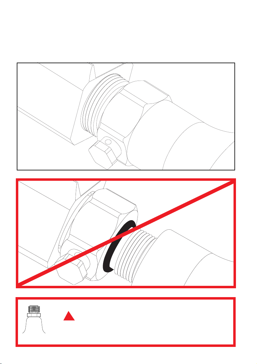
The CO2 or Compressed Air Tank can y off with enough force to cause serious
!
DA N
3
G E R
injury or death if the Valve unscrews from the cylinder head. LOOK at the Valve
when removing the cylinder from the marker. Be sure that the valve is turning
with the cylinder rather than remaining stationary with the marker. STOP if the
Valve starts to unscrew from the cylinder. If in doubt, screw the cylinder back
onto the marker and contact a trained person for repair.
Page 7

IN STALL ING A CO2 / COMPRE SSED AIR TANK
Firmly, attach the CO2 / Compressed Air Tank clockwise to the markers Dovetail Bottom Line ASA (#261).
HELPFUL TIP: Make sure when installing a tank, to have the CO2 / Commpressed Air Tank lled. Make sure the CO2
/ Compressed Air Tank has a bottle o-ring on the top of the valve to prevent air leaks.
RE MOVI NG A CO2 / COMPRES SED AIR TANK
Firmly, unscrew the CO2 / Compressed Air Tank by turning counter-clockwise.
HELPFUL TIP: After playing with the marker, you should ALWAYS remove the CO2 / Commpressed Air Tank. When
the Tank is being removed, excess air will release from the bottom of the Dovetail Line ASA (#261).
IMPORTANT: Never expose any skin underneath the Dovetail Bottom Line ASA (#261) when removing the Tank.
This can run the risk getting skin burn from releasing the GAS. Never store any CO2 / Comppressed Air Tank
attached to the marker.
CO2 / COMPRE SSED AIR TANK WARNIN GS
• All valves must only be installed or removed by a qualied airsmith.
• See CO2 / Compressed Air tank labels for retest dates. Cylinder tanks must be retested periodically.
• Improper use, lling, storage or disposal of all air cylinders may result in death, personal injury and/or
property damage.
• Always keep cylinders out of reach from children or any inexperienced person(s).
• Only properly trained personnel in accordance with CGA Pamphlets P.1 and G-6.3 must ll all air cylinders.
Pamphlets are available from the Compressed Gas Association or www.CGANET.com.
• Never alter the cylinder in any way.
• DO NOT expose pressurized cylinders to temperatures in excess of 130˚F (54˚C).
• Cylinders heated to an excess of 250˚F (121˚C) must be condemned or requalied in accordance with test
dened in CFR-49.
• The valve should NEVER be detached from the canister. Please seek immediate assistance from a trained
airsmith should this occur.
• Any tank packed with the product is intended for paintball use only.
• Conrm that there is an attached urethane O-ring on the CO2 / Compressed Air tank valve before attaching the
tank to the marker. The tank will leak air as soon as it is secured to the marker, if the O-ring is missing from
the valve.
• A urethane O-ring is highly recommended before attaching any air supply to the marker.
• NEVER over pressurize a CO2 / Compressed Air cylinder.
• Avoid any direct skin exposure to the escaping gas, when installing or removing any air supply.
• Never expose cylinders to corrosive materials or clean with any caustic cleaners.
4
Page 8
OFF
LED LIGHT
SEMI/EYES
SEMI
AUTO
EL ECTRON ICS & SE TTINGS
#270
#E24A
#JE101S
#JE30B
CH ARGI NG
PO RT
#294
EL ECTRON IC GRIP TROUBLES HOOTIN G
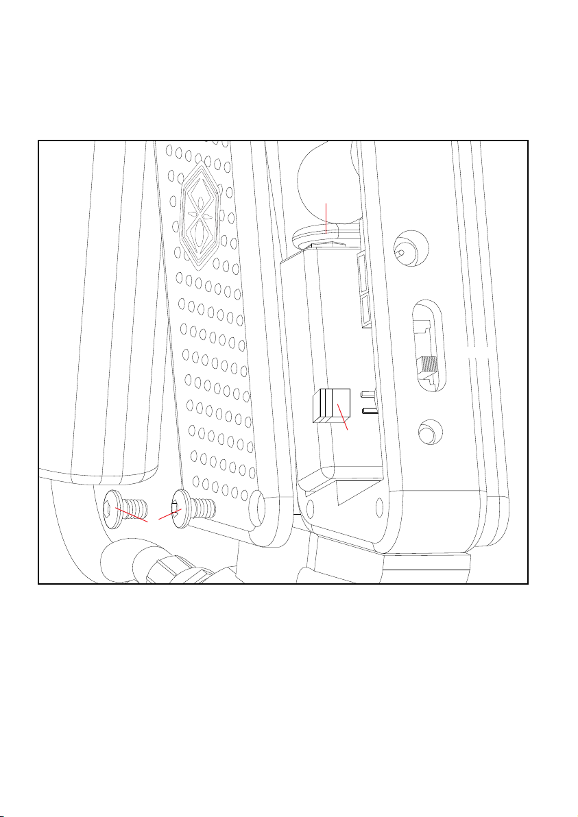
• Check to make sure there is enough air pressure to re the marker.
• Battery may need to be recharged.
• If the Trigger is not functioning, turn the Trigger Screw (#298) clockwise to shorten the gap between
the Touch Switch (#272) using an allen wrench. NOTE: Do not over extend the Trigger Screw (#298) for this can
cause the Touch Switch (#272) to stick.
• Everytime the trigger set screws are repositioned use thread locker “Loc-Tite” 242 (Blue color) to prevent
from loosening.
5
Page 9

IN STALL ING A BATT ERY
STEP 1 Remove the 3 M4x8 screws (#294) and left side grip panel (#270).
STEP 2 Attach the Spyder battery (#JE1015) to the Battery Harness (#E24A).
STEP 3 Retighten the 3 M4x8 screws (#294).
HELPFUL TIP: Please note how the parts are rem oved for ea sy reas semb ly.
RE MOVI NG THE TOUR NAMENT LOCK SWITCH
STEP 1 Remove the 3 M4x8 screws (#294) and left side grip panel (#270).
STEP 2 Remove the Tournament Lock Switch (#JE30B) located to the right of the Spyder Battery.
HELPFUL TIP: Having the Tournament Lock Switch removed from the circuit board will deactivate auto.
MO DE SET TINGS
Mode Switch Down is in the OFF Position.
MODE 1 Click Up is in Semi-Auto with Eyes ON.
MODE 2 Click Up is in Semi-Auto with Eyes OFF.
MODE 3 Click Up is in Auto with Eyes OFF.
TOURNAMENT M ODE SETT ING
The MR3 Circuit Board (#331) is equipped with a Tournament Lock Out Switch (#JE30B). When the Tournament
Lock Switch is removed from the Circuit Board the marker can only re in SEMI-AUTO. The Tournament Lock
Switch is located on the internal Circuit Board to the right of the Battery. Reattaching the Tournament Lock Switch
(#JE30B) back into the Circuit Board will re-enable the multi-mode functions.
IMPORTANT! Kingman recommends that you use a force feed / high speed electronic loader to reach optimum
performance. Kingman also recommends the use of a Spyder CO2 / Compressed Air Tank to operate this marker.
Lastly, the use of tournament grade paint will help reduce the likelihood of paintball breaks when ring the marker.
WARNING
• The Spyder Electronic Markers are not water resistant.
• Extreme moisture can cause serious damage to any Spyder Electronic Markers.
• Always clean any dirt or paint inside the Markers Electronics.
• Never attempt to modify the Electronics circuitry. Doing so, it will VOID all electronic warranties.
NOTE: If the Markers Electronics have any dirt or paint, Kingman recommends using an aerosol can of air. Apply the
can of air directly at the components that need cleaning.
6
Page 10
BATT ERY CH ARGING
#JE1024
or
#JE1025
LE D
LI GHT
7
Page 11

CH ARGING INSTRUC TIONS
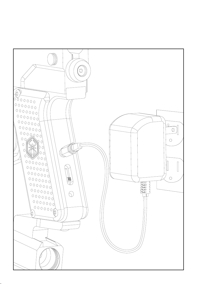
To charge a Spyder 9.6 NiMH Battery the circuit board must be in the OFF Position. Spyder Batteries (#JE1015) are not fully
charged when purchased. Using the supplied Spyder Charger (#JE1024) place the charger in the charging port which is located at
the rear of the trigger frame. Kingman recommends a charging time of 6-8 hours for a complete charge.
IMPORTANT: You should never charge the battery over 24 hours or you can run the risk of damaging the battery or electronics. The
battery charger will continue to power until removed from charging port.
NOTE: It is recommended that the battery be chagred prior to use in order to ensure maximum performance, especially if the battery
has not been used in over a week.
SPYDER 9.6 Ni MH BATTERY LIFE
Always use the supplied Spyder 9.6volt NiMH Battery and Spyder Charger to operate this marker. A fully charged Spyder Battery
will last about 3000 to 5000 shots. Number of shots depends on the settings of your ring methods. Under normal use and charging
conditions the expected life of the Spyder 9.6 NiMH Battery to last approximately 700-1000 charging cycles.
WARNING: This marker is not attended to use any normal 9 volt battery or chargers that are NON Spyder Products. Doing so will
VOID all electronic warranties.
LOW BATTERY INDIC ATOR
The LED light located beneath the mode switch on the back of the grip will blink rapidly when the battery power is
low and will require charging.
8
Page 12
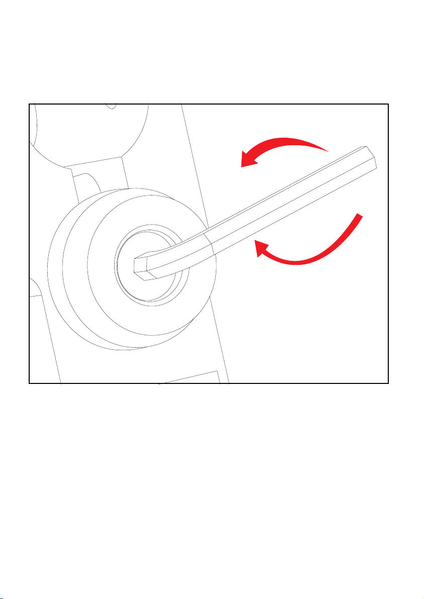
VE LOCITY ADJUS TMENT
Decrease Velocity
#296
#260
VE LOCITY ADJUS TMENT INCREAS E/DECREA SE
Increase Velocity
To increase your velocity FPS (Feet per second) using the allen wrench turn the Velocity Adjuster (#296) clockwise.
To decrease your velocity FPS (Feet per second) using the allen wrench turn the Velocity Adjuster (#296) counterclockwise.
NOTE: Velocity Adjuster w/Spring Guide (#296) doesn’t remove from the rear of the Striker Plug (#260).
WARNING
• The recommended Velocity speed should be no greater then 300fps. Not doing so can cause serious injury if the
velocity is dangerously high.
• Paintball markers are not intended to shoot any person less then 25 feet.
• Never point a loaded marker at any person who is not wearing the proper face protection.
• Never at any time should you look down the barrel when the marker is loaded or not.
• Using a paintball marker outside a non designated paintball eld can be illegal, and is subject to law enforcement
penalties if property damage is caused by the user.
9
Page 13
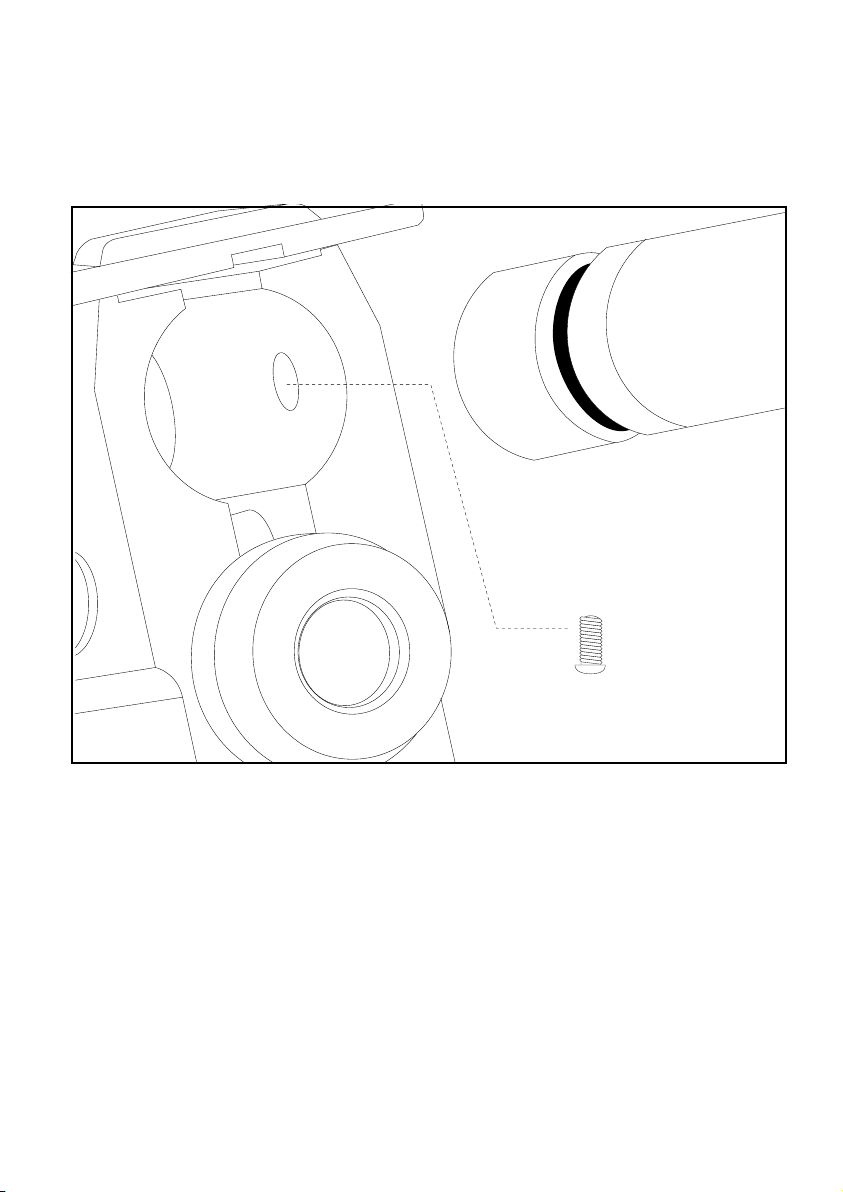
SH OULDER STOCK IN STALL ATION
I>EKB:;HIJE9A
#325
#332
#16
SH OULDER STOCK IN STALL ATION
Place the Shoulder St ock (#332) on the back end upper section of the Re ceiver (#325). Once the
Shoulder Stock is in place tighten the Set Scre w (# 16) to s ecur e th e stock to the body of the marker.
The Set Screw (#16) is located on the right side of the re ceiv er.
ADJUSTI NG SHO ULDER STOCK L ENGTH
* Tu rning the Shoulder Sto ck Scre w (# 333) cou nter-clockwise will loosen the Shoulder Stock allowing
for three differ ent leng ths to be achieve d.
* Not Pic tured .
10
Page 14
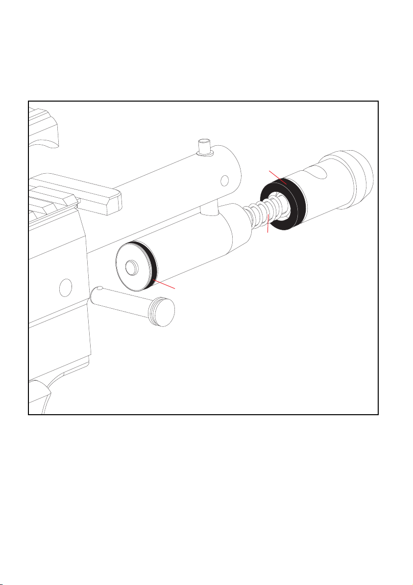
DI SASSEM BLE / RE ASSEMBLE & CLE ANI NG INTER NALS
#26A
#326
#25
#JE18A
#19 A
#262
#260
TR OUBLES HOOTIN G
ON E O R MO RE OF THE FOL LOWI NG MAY CA USE REC OCK ING REL AT ED PRO BLEM S:
• The pressure i n th e tank is too low. In some cases, the wea ther can affe ct the liquid in the tank
and not cause it not to expand int o carbon diox ide gas.
• Marke r ne eds lubrication.
• Ven turi Bol t (#326) n eeds to be cleane d.
• The Striker O-r ing (#19A) is damaged. Rep lace with new Kingman or Kingman-ap proved O-ring.
NOTE : Th e O-ring (#19) cannot be substituted by a tank O-ring or an #09 O-ring.
• Need to clean Barrel and upper chamber of the Receiv er ( #325).
• Paint balls may be defect ive (i.e. expired, odd shape, e tc.)
• After ball bre aks in Barrel or chamber, remove all parts from upper chamber of Recei ver, wipe
parts clean, and reas semb le parts into Rec eiver. Al so make sur e to cle an t he Barrel with a squeegee.
11
Page 15

DI SASSEM BLE REAR INTERNA LS
ST EP 1 Remove Qui ck Disconn ect Pin (#262). NOTE : Pl ace a fi nger ov er t he S trik er P lug (#260)
before rem ovin g th e Quick Disco nnect Pin (#262)
ST EP 2 Remove the Str iker Plu g (#262) Main Spring (#25) St rike r Bu ffer (#2 6A).
ST EP 3 Remove the fol lowing items at the same time. Stri ker Bolt (#J E18A) a nd t he Delrin Venturi
Blot (#326).
HELPFUL TIP: Please note how the parts are rem oved for ea sy reas semb ly.
RE ASSEMBLE REAR IN TERNAL S
When reas semb ling the Delrin Venturi Bolt (#326) and Str iker Bol t (# JE18A) the circ uit board must be
powered ON with the Eyes OFF. Join the Delrin Venturi Bolt (#326) and St rike r Bo lt (#JE18A)
together entering the back end of the Rece iver (#3 25). Simultaneously pull the Blade Trigger (#273)
and apply pressure beh ind the Delrin Venturi Bolt (#326) to allow reen try of both parts. Rein stal l the
Strike r Bu ffer (#26A) , St riker Spring (#25) Striker Plu g (#260) a nd p ress in the Quick Discon nect Pi n
(#262) to lock down all back internals.
HELPFUL TIP: When the back int ernals are rem oved it would be wise to clean any dirt or paint f rom
inside the Rece iver (#3 25) with a stick swab or cable squeegee. Wip e th e De lrin Venturi Bolt (#326)
with a ra g or paper towel. The Str iker O-R ing (#19 A) will need to be oiled periodically. Kingman
recomm ends that eac h time the back int ernals are rem oved the St rike r O- Ring (#19A) should be oiled.
IMPORTANT: N ever oil the Delrin Venturi Bolt (#326). This will swell the bolt and cause cock ing
problems. St rike r Bu ffer (#2 6A) shou ld be installed behind the Stri ker Bolt (#JE18A) to e nsure p rope r
functioning.
WARNING: Neve r at temp t to re move the markers int ernals while the CO 2 / Com pres sed Air bottle is
attached. Make sure to remove all paintb alls and loader before dis assembling the marker.
12
Page 16
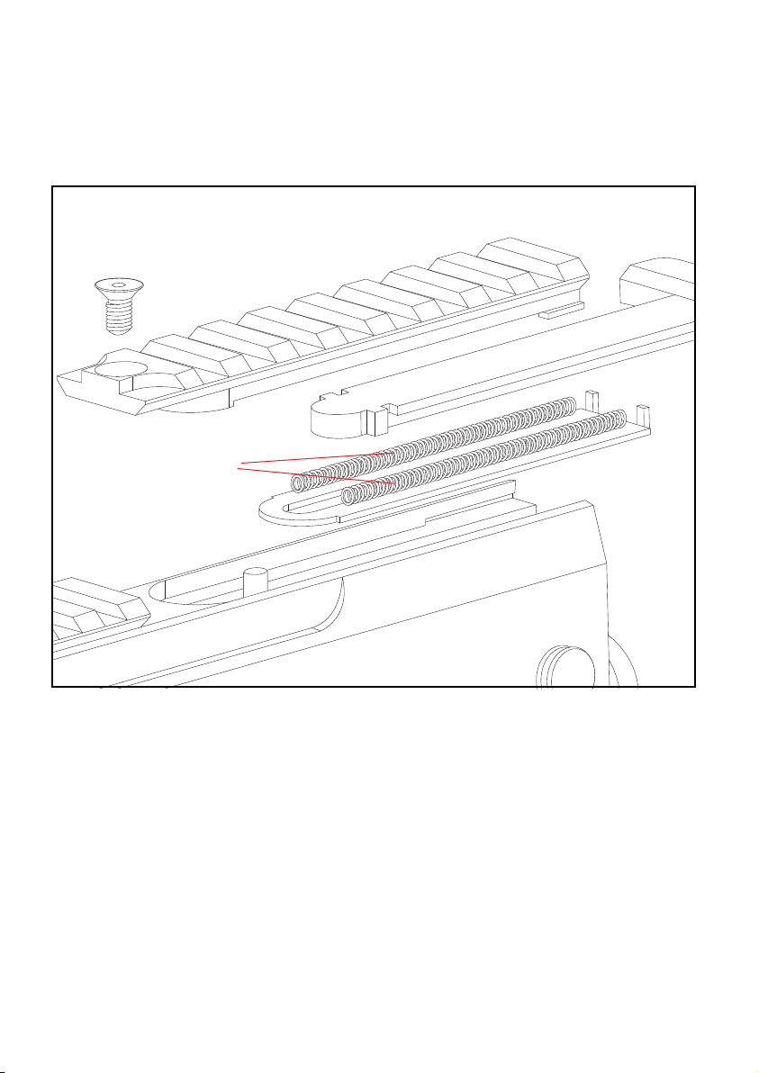
T-COCKING REMOVAL
#334
#268
#267
T-COCKING REMOVAL
STEP 1 Remove Flat M4 x 8 Screw (#334).
#269
#266
STEP 2 Slide the Snap Rail Cover (#269) toward the rear of the marker.
STEP 3 Remove Snap T-Knob (#266).
STEP 4 Remove the Snap T-Clip (#267). NOTE: Be careful while removing the Snap T-Springs (#268) as the tension
may cause them to y off.
HELPFUL TIP: Please note how the parts are rem oved for ea sy reas semb ly.
13
Page 17
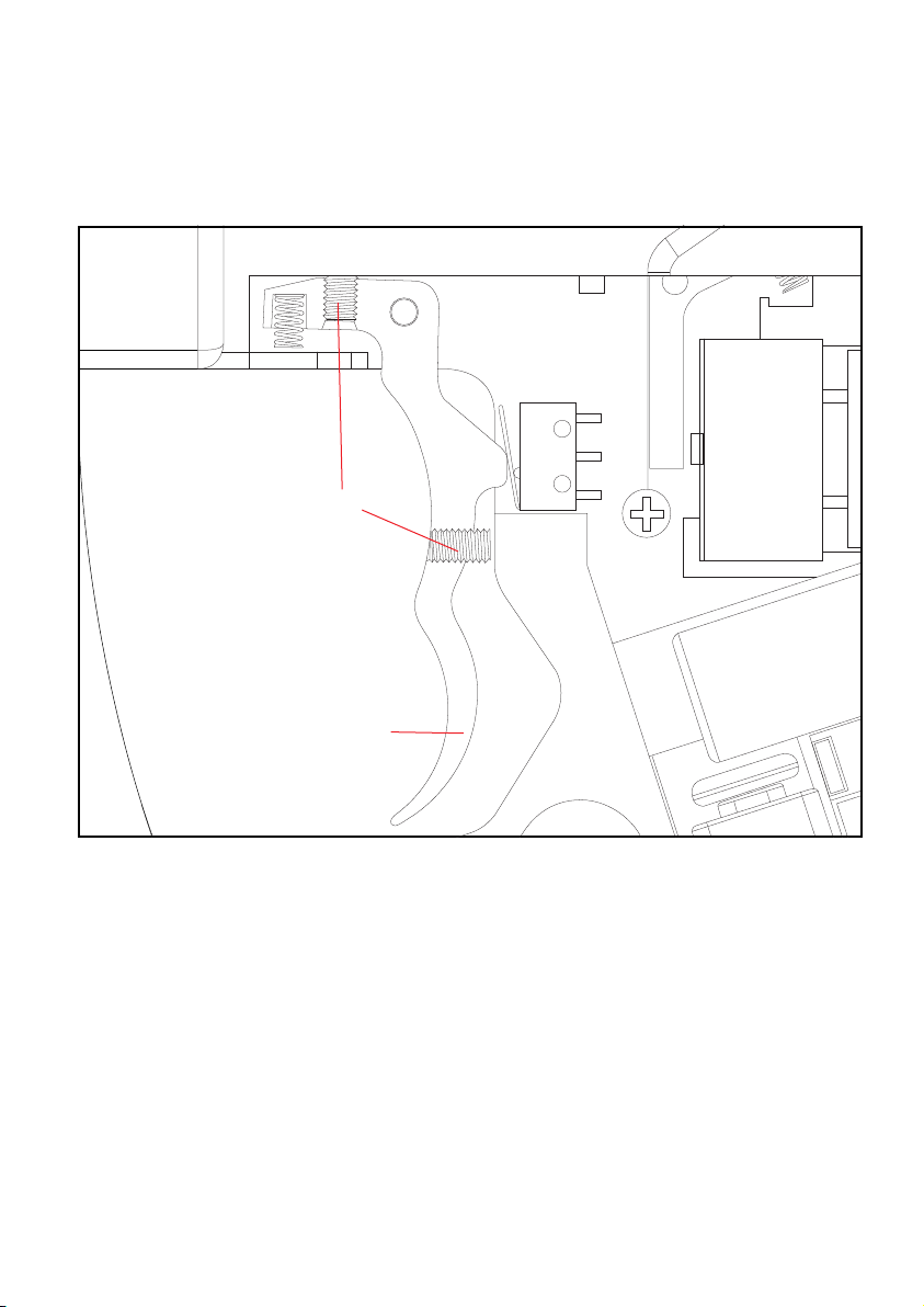
TR IGGER ADJUSTMENT
#272
#298
#273
TR IGGER ADJUSTMENT
Adjusting the Top Trigger Set Screw (#298) clockwise will swing the Trigger (#273) closer the Touch Switch (#272)
which will lessen the trigger gap. NOTE: Adjusting the Trigger Set Screw (#298) counter-clockwise will increase the
trigger gap.
Adjusting the lower Trigger Set Screw (#298) clockwise will shorten the Trigger (#273) stroke to the Touch Switch
(#272) this will increase Trigger (#273) sensitivity. NOTE: Adjusting the Trigger Set Screw (#298) counter-clockwise will decrease the Trigger (#273) sensitivity.
14
Page 18
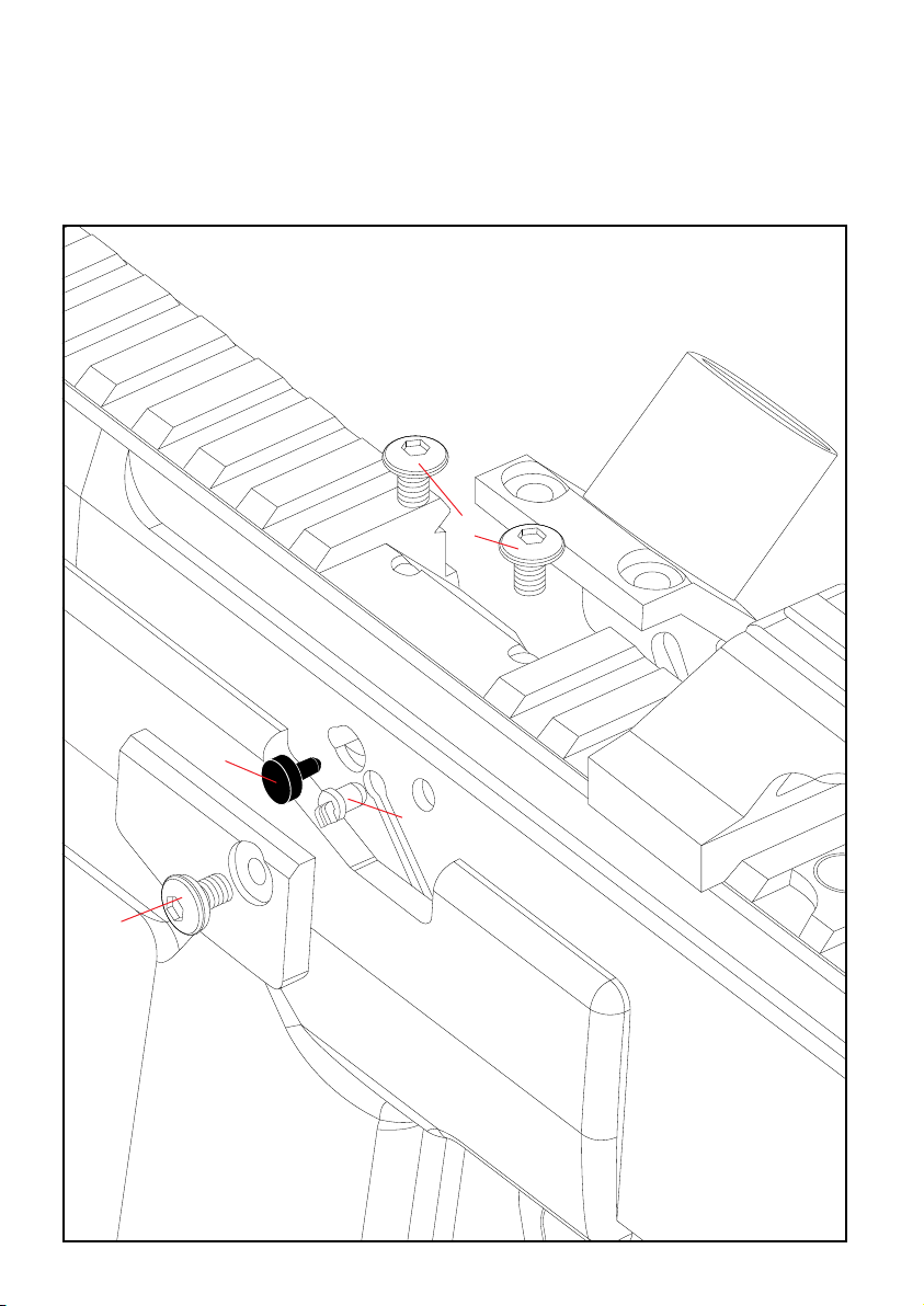
AN TI CHO P EYES
#03
#321
#294
15
#294
#329
#243
Page 19

AN TI CHO P EYES
The Anti Chop Eyes help prevent chopping paint b y not allowing the marker to fire unt il a paint ball is in
fro nt o f th e Venturi Bolt. The Eyes tran smit a beam across the inside of the bree ch. The Circu it B oard
is preset from the factory and does not need to be adjusted or altered . If the Ey es a re O N and do not
see each other when firing your marker, you will have to clean the Eye s.
CL EANING T HE ANT I CHOP E YES
Using a squeegee or swab thru the breech should clean the Eye s en ough fo r the beam s to detect each
other. Anot her way is to use an aero sol can of air thru the bree ch t o re move paint or dirt from the Eye s.
To th orou ghly clean the Eye s re move all M4 x 8 Scre ws (#294) (inc luding the lower screw not pictured
which holds the Fe ed N eck) , th e Ey e / Detent Cover (#329) and the Fee d Ne ck ( #321 ) us ing an allen
wrench. Once the M4 x 8 Scre ws ( #294), Eye / De tent Cover (#329), and Fee d Ne ck ( #321 ) are
removed, precede with a soft pinch to rem ove the Eye Wi re Harness (#243) from the receiv er. Re move
all dirt or paint that is blocking the Eye s and causing it to malfunction.
HELPFUL TIP: Please note how the parts are rem oved for ea sy reas semb ly.
IMPORTANT: C lean ing the Eye s often will help redu ce d irt, paint or oil res idue that blocks the Eyes
fro m se eing ea ch other.
NOT E: N ever attempt to rush the cleaning proc ess or you can pinch the wire s an d cause the marker to
malfunction with the Eye Mo de ON. Take precaution not to over tig hten the M4 x 8 Screw (#294) or
this can lead stripping the head.
CH ANGING THE BALL DET ENTS
Experiencing paint ro lling thro ugh the barrel, can be related to small diameter of paint balls or the lost
of a ball detent(s).
When remo ving the Eye / Detent Cover (#329) a nd Feed Neck (#321) the Ball Detents (#03 ) wi ll
become acces sabl e to be clean ed or repl aced .
HELPFUL TIP: Please note how the parts are rem oved for ea sy reas semb ly.
NOT E: Take precaution not to over tighten the M4 x 8 (#294) or this can lea d to stripping the hea d.
16
Page 20
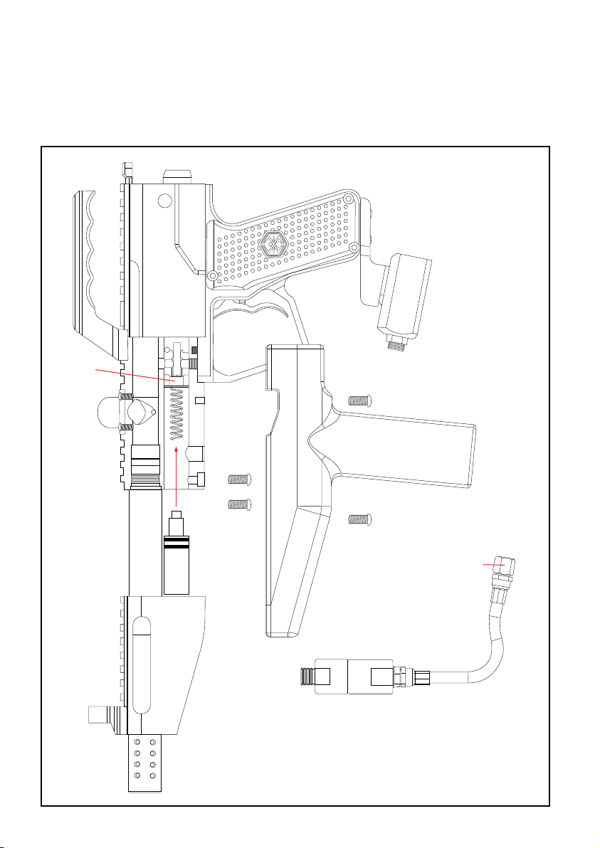
CU P SEAL R EMOVAL
#12
STEP 4
#16
#16
STEP 3
#327
#16
17
#254
STEP 5
#322
STEP 2
STEP 1
COLLAR
#290
Page 21

ST EP BY STEP CUP SEAL ACCESS
The following steps will provi de e asy acce ssto the Cup Sea l (#12).
The sign of a worn out Cup Sea l (#12) is the pres ence of CO2 /Compres sed Air leaki ng down the barrel.
ST EP 1 Loosen the Discon nect Ho se (#290) from the collar.
ST EP 2 Loosen the 2 set screws M5x12 (#16).
ST EP 3 Remove t he Fore Grip Hand le (#327).
ST EP 4 Loosen the 2 set screws M5x12 (#16).
ST EP 5 Remove t he S hrou d (#322).
Once the steps have b een com pleted, this will allow the Res ervo ir P lug (#254) to slide out with the
Valv e Sp ring (#10C ), C up S eal Guid e (#11) , Cu p Se al ( #12) and Valve Pin (#13).
HELPFUL TIP: Please note how the parts are rem oved for ea sy reas semb ly.
HE LPFUL HINTS
Always remove the Air Tank before any disassembly of your marker. Do not rem ove the Valv e Bo dy
(#14) unless specific Valve Body repairs are need ed. If needed, re move Valv e Bo dy with a long, softtipped object such as the eras er end of a pencil. Do not remo ve the Valve Bod y with a scre wdri ver as it
will damage the Val ve B ody and cause air leaks . NOTE: Valve Body (#15) scre w must be rem oved prior
to taking out the Valv e Bo dy
18
Page 22
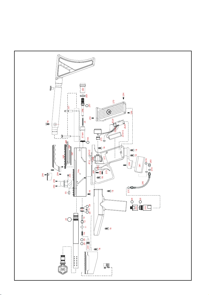
325
JE18C
321
334
2608S
01
328
2608S
329
262
326
37B
331
243
327
322
320
323
324
332
333
16
MR 3 SCHEMATICS
19
Page 23
MR 3 PAR TS LIST
01 Barrel Plug
03 Ball Stopper
09 O-Ring #015 80D
10C Valve Spring
11 Cup Seal Guide
12 Cup Seal
13 Valve Pin
14 Valve Body
14A Valve Body Roll Pin
15 Valve Body Screw
16 M5 x 12 Screw w/ washer
19A Striker O-Ring
20 Barrel O-Ring
25 Striker Spring
26A Striker Buffer
37B Filter O-Ring
37C Air Filter
49 Trigger Pin
49B Sear Roll Pin (Small)
49C Touch Switch Roll Pins
243 MR3 Wire Harness
252 MR3 Vertical / C/A Adapter
253 MR3 Vertical / C/A to Hose Adapter
254 MR3 Reservoir Adapter Plug
257 MR3 Bolt Pin
258 MR3 Dovetail Drop Forward
260 MR3 Striker Plug
261 MR3 Dovetail Bottom-Line ASA
262 MR3 Quick Disconnect Pin
266 MR3 Snap T-Knob
267 MR3 Snap T-Clip
268 MR3 Snap T-Spring
269 MR3 Snap Rail Cover
270 MR3 Grip Panels
272 MR3 Touch Switch w/ Wire Harness
273 MR3 Blade Trigger
276 MR3 Parts Kit
*
283 MR3 Male STD / Female Metric
290 MR3 Disconnect Hose 6.25” (black)
294 M4 x 8 Screw w/ Washer
296 MR3 Velocity Adjuster w/ Spring Guide
297 MR3 Velocity Adjuster O-Ring
298 Trigger Set Screw
320 MR3 10” Barrel
321 MR3 Feed Neck
322 MR3 Shroud
323 MR3 Rie Sight
324 MR3 Rie Sight Screw
325 MR3 Receiver
326 MR3 Delrin Bolt
327 MR3 Fore Grip Handle
328 MR3 Sight Rail
329 MR3 Eye / Detent Cover
330 MR3 Trigger Frame
331 MR3 Circuit Board
332 MR3 Miltary Adjustable Stock
333 MR3 Military Adjustable Stock Screw
334 Flat M4 x 8 Screw
2608S Drop Forward Lock Screw
E24A Battery Harness
JE12 Sear
JE18A Striker Bolt
JE18C Coil Set
*
JE18E Coil Set Screw
JE29 Circuit Board Screw
JE31E ESP Sear Spring
JE1015 9.6v Rechargeable Battery
*
JE1024 A/C Charger - 110v
* Not Pictured
20
Page 24

WARRANTY STATEMENT
Kingman warrants the original retail purchaser that this product is free from defects in material and workmanship
under normal use and service for a period of (1) year from the original date of purchase. Any Electronic Components
in an Electronic Spyder marker are warranted for (6) months from the original date of purchase. Kingman agrees to
repair or replace (at its discretion) any product within (a reasonable period of time). This warranty does not cover
o-rings, cup seals, 9.6v rechargeable battery, charger, scratches, nicks, normal wear and tear of parts, any modications, normal fading of anodizing and damage caused by dropping or hitting of products. This warranty shall not
apply if it is shown by a Kingman Technician that the consumer caused the defect or malfunction because of misuse.
This warranty only covers original factory parts. Any modications or tampering of original factory parts will VOID
warranty. Any damage caused by water will not be covered under warranty. Warranty repair can only be conducted
by Kingman technician or Kingman authorized technician. For warranty to be effective, consumer must return the
enclosed warranty registration card lled out, along with a copy of the purchase receipt, within (15) days of the
original purchase date. This warranty is not transferable. Paintball markers are non-refundable. This warranty will
not cover pick up, shipping, delivery, and/or house calls. If product needs repair, consumer will package it carefully
and send together with your name, address, phone number and a brief description of the malfunction to:
KINGMAN GROUP
Attn: Tech Department
14010 Live Oak Avenue
Baldwin Park, CA 91706 U.S.A.
www.kingman.com
FOR TECHINICAL SUPPORT
Our Technical Support Department is open Monday through Friday, from 8am to 5pm (PST), and can be reached at
(626) 430-2300.
21
www.spyder.tv
Page 25
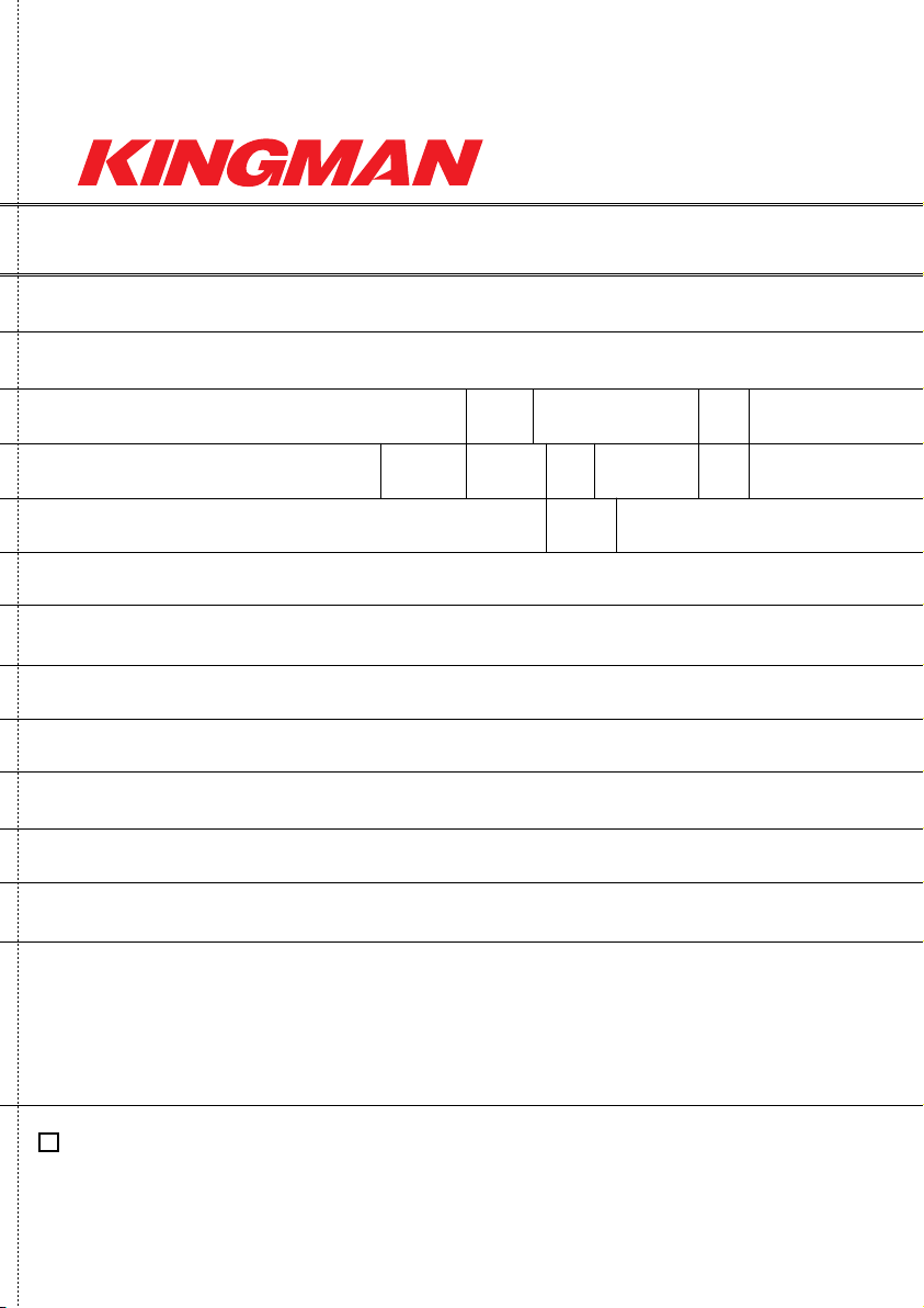
WARRANTY
REGISTRATION
PLEASE CO MPLE TE AND RETURN THIS FO RM, ALON G WI TH A COP Y OF YOU R PU RCHA SE RECE IPT,
WITHIN 15 DAYS OF PURC HASE SO THAT WE MAY VA LIDATE YOUR 12 MONTH LIMITED WARRANT Y.
NAME:
ADDRESS:
CITY: STATE : ZI P:
COUNTR Y: GE NDER: AG E: JOB:
E-MAIL : P HONE :
PRODUCT N AME/SER IAL #:
WHAT OTHER BRAND( S) OF M ARKERS DO YOU OWN?
WHY DID YOU P URCHASE THIS K INGMAN MARKER?
WHAT IS T HE N EXT PAINT BALL PRODUC T YO U IN TEND TO BUY?
WHAT ARE YOUR HOB BIES (OT HER THA N PAI NTBA LL)?
WHAT ARE SOME MAG AZIN ES YOU L IKE TO READ?
HAVE YOU MAD E ANY O NLINE P URCHASE S IN TH E PAS T 6 MON THS? Y / N
COMMEN TS / SU GGESTIO NS:
YES , I WOUL D LI KE TO RE CEIV E M ORE INFO REG ARDI NG N EW PROD UCTS , PR OMOT IONS , AN D SP ECI AL O FFER S
FRO M KI NGM AN.
MAIL TO:
KINGMAN G ROUP 14010 LIVE OAK AV E. B ALDW IN PA RK, CA 91706 US A
22
Page 26

Page 27

Page 28

 Loading...