

Page 1
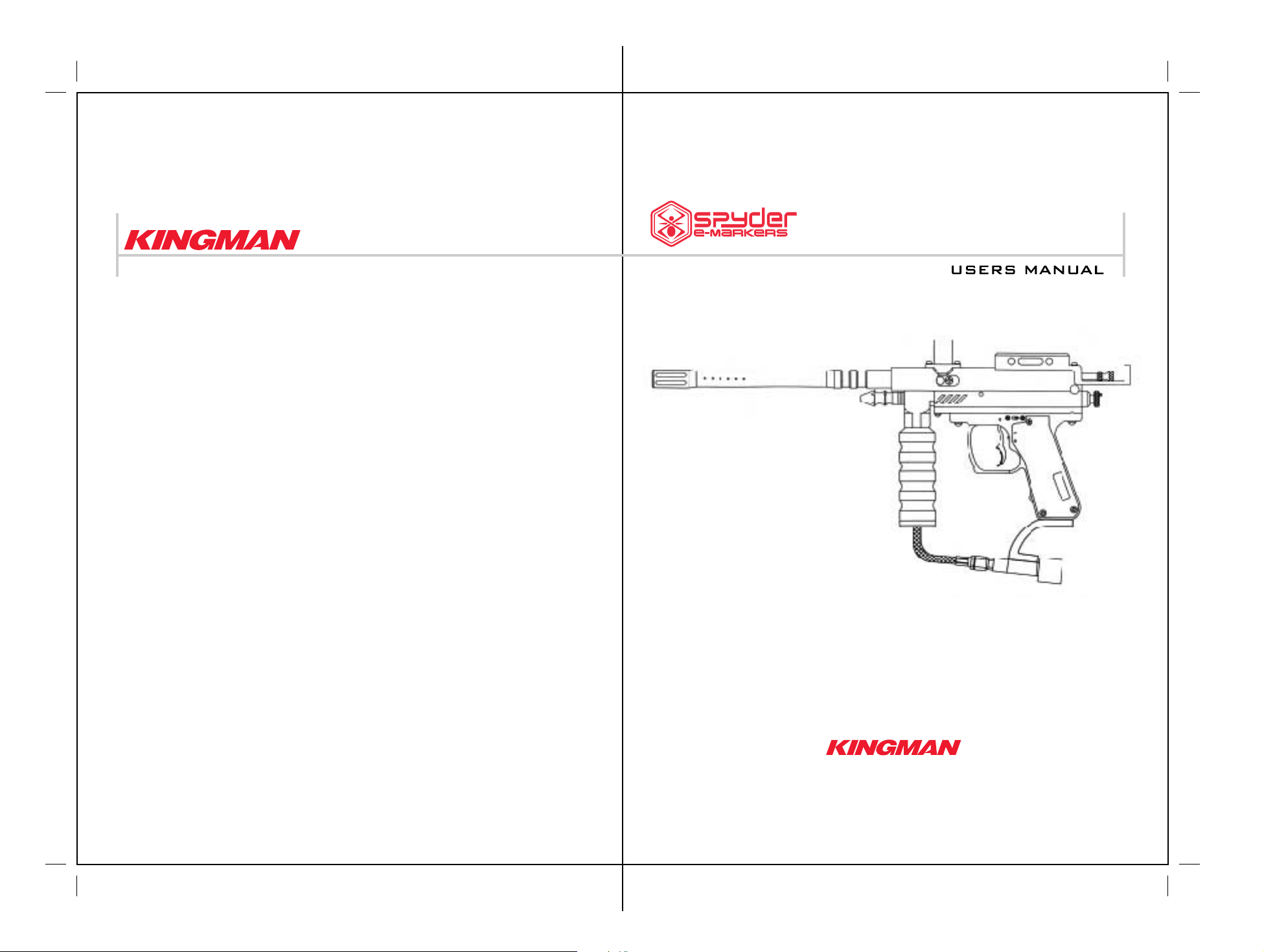
Kingman Group 14010 Live Oak Avenue, Baldwin Park, CA 91706, U.S.A.
Toll-free 888.KINGMAN
www.kingman.com
E99
AVANT
JAVA 9.6V RECHARGEABLE BATTERY & CHARGER INCLUDED
14010 Live Oak Avenue, Baldwin Park, CA 91706, U.S.A.
Telephone: 626-430-2300 Fax:626-851-8530
Website: www.kingman.com
Page 2
CAUTION
• This paintball marker is NOT a toy. It can cause serious injury or death.
• Recommend at least 18 years of age to purchase this product.
• Install a barrel plug in the barrel when not actually playing.
• All persons using this product, or within range while this product is being used,
must wear eye and face protection specifically designed for paintball.
• Never shoot a person who is not wearing proper protection.
• Treat every paintball marker as if it were loaded.
• Never look down the barrel of the marker.
• Keep the paintball marker on safe until ready to shoot.
• Always remove gas source before disassembly.
• Fire only 0.68 caliber paintballs from this product.
• Read this manual and air system warning before using this product.
• Transfer this instruction manual upon change of marker ownership.
CO2/HP AIR TANK WARNING
WARNING
• VALVES MUST BE INSTALLED OR REMOVED ONLY BY QUALIFIED PERSONNEL.
• BOTTLE MUST BE RETESTED SEE CO2/HP TANK LABEL FOR RETEST DATE!
• Improper use, filling, storage or disposal of this cylinder may result in death, personal
injury and property damage.
• This cylinder must be filled only by properly Trained personnel in accordance with CGA
Pamphlets P.1 and G-6.3 available from the Compressed Gas Association
www.CGANET.COM
IMPORTANT
• Firing velocity may vary according to altitude and climate conditions.
• BEFORE using your marker in play, you must always first perform a
“SAFE VELOCITY TEST”. This can only be accomplished by using a testing device
called a “Velocity Chronograph” and can be performed by the dealership where you
purchased this product or at a local paintball playing field.
• NOTE: This product is intended to be used at a velocity no greater than
300 feet per second (FPS).
• Recommended velocity is 280 FPS or less.
• This product is NOT intended to be used at any distance less than 25 feet.
• This paintball marker may have excess gas after removal of the tank. Please remove all
paintballs and discharge the remaining gas safely.
• Do not over pressurize. Do not expose pressurized cylinder to temperatures in excess of
130 degrees F.
• Do not expose cylinder to corrosive materials and do not clean with caustic cleaners.
• Do not alter this cylinder in any way.
• Cylinders heated to a temperature of 250 degrees For more must be condemned or re qualified in accordance with test defined in CFR-49.
• Keep cylinder out of reach of children.
• The valve should NEVER be detached from the canister. Should this occur, please seek
assistance from a trained airsmith immediately.
• This tank is intended for paintball use only.
P1
Page 3
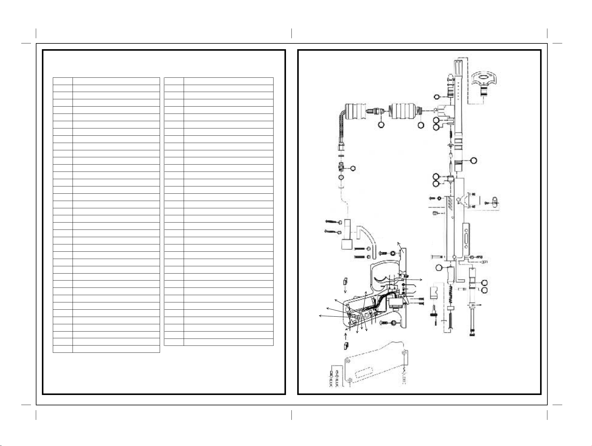
Spyder E99 Avant (black & green)
2208L
ITEM # NAME OF PARTS ITEM # NAME OF PARTS
01 Spyder Barrel Plug 27A Flat Disc
2202 12" Barrel (Black) 29B Lock Screw
04GA Mini Detent Cover (Black) 2229C Thumb Adjuster w/ Screw (Silver)
05A M4 x 6 Screw (Black) 23321 E-99 Grip Cover (Black)
05B M4 x 6 Screw (Silver) 33F Compact Nut Screw
05C Direct Feed Screw 36D 5/32" x 5/8" Screw (Black)
07 M5 X 14 Screw w/ Washer 36E 5/32" X 7/8" Screw (Black)
09 O-Ring #015 80D 37A Filter O-Ring
10A Valve Spring 37B Air Filter
11 Cup Seal Guide 37C Disconnect O-Ring #011 (Black)
12 Cup Seal 37D Plastic Washer
13 Valve Pin 37J Disconnect Hose
14 Valve Body 41J E99 Spare Parts Kit
15 Valve Body Screw 2247 Sight Rail with Beaver Tail (Silver)
16D M5 x 12 Screw w/ washer 2247B Sight Rail with Beaver Tail (Black)
17JA E99 Venturi Cocking Bolt (Black) 49 Sear Roll Pin (Medium)
19A Striker O-Ring 49B Secondary Sear Roll Pin
20 Barrel O-Ring (Black) 49C Touch Switch Roll Pin
21 Bolt Pin E24 On/Off Switch with Wiring Harnesses
22041 Direct Feed (Green)
22042 Direct Feed (Black)
2106G E99 Receiver (Green)
2206B E99 Receiver (Black)
2208L Low Pressure Chamber (Matted Silver)
2235L Drop Forward (Matted Silver)
2244H Expansion Chamber (Silver)
22 Bolt Screw
2208B Vertical Adapter (Black)
2228B Striker Plug (Black)
2235B C/A Adapter (Black)
2244B Mini Fore Grip (Black)
22B M4 X 8 Screw w/Washer (Black)
23B Quick Disconnect Pin
23C Disconnect Pin Lock
25 Striker Spring
26A Striker Buffer
27 Striker Spring Guide
E24A Battery Harness
E33 On/Off Screw (M2 x 6 Screw)
JE1015 Java 9.6v Rechargeable Battery
JE12 Trigger Sear
JE18A Striker Bolt
JE18C Coil Set
JE18E Coil Set Screw (A)
JE26 Charge Pin
JE28A Battery Low Indicator
JE28B1 Low R.O.F. Indicator
JE28B2 High R.O.F. Indicator
JE28C1 Single Shot Indicator
JE28C2 3 Round Burst Indicator
JE28C3 Full Auto Indicator
JE28N IPI 3.0 Circuit Board
JE29 Circuit Board Screw
JE33C Grip Cover Screw (Black)
36E36E
JE28C2
JE28C1
37J
37D 42F
JE28C3
JE28D
33F33F
37A 37B
2235B
2244B
37C
36D
36D
1015
JE29A
JE28B1
2235L
JE30B
JE
JE28B2
JE28A
JE29
JE26
JE28N
37C
16
JE31C
JE27
16
JE31
JE31F
49C
JE18C
23321
2244H
JE12
JE31E
9
JE31D
E24
49B
E33
15
9 9 9 9
16
49
JE18E
9
15
23B
19A
2228B
2229C
29B
10A 12 13
11
14
JE18A
27A
2202
2208B
2206B
25
26A
27
2106G
21
05C
22042
05C
2247B
2247
20
22041/
17JA
05A
05B
22
01
SPYDER E99 Avant Parts List
04G
23C
9 9
P2 P3
Page 4
OPERATION GUIDE
Put the marker on 'SAFE' by pushing the on/off switch to the right. The marker is now off. To
1)
power on the marker, push the on/off switch to the left. CAUTION: with the power on, the
electronic circuit board is now powered on and ready to shoot.
Cock the marker by pulling the E99 Avant Venturi Cocking Bolt (#17JA) rearward until it latches.
2)
Caution: if you let go before it latches, your marker may fire.
Tighten the air tank until it is snug. If a leak occurs between the tank and the C/A adapter,
3)
replace the tank o-ring.
Install a 7/8th vertical elbow with loader onto the direct feed. Fill the loader with .68 caliber
4)
paintballs only.
Please refer the IPI-3.0 mode settings guide on page 6,7 to set the R.O.F. and mode in grip
5)
frame.
With the safety off, fire the marker by pulling the trigger.
6)
Only use lubrication specifically designed for paintball markers. To lubricate your marker, you will
7)
need to disassemble your marker (please note how parts are removed from marker as this will
ease re-assembly). Remove the Disconnect Lock Pin (#23C) and the Quick Disconnect Pin
(#23B). Hold down the Striker Plug (#2228B) and Thumb Adjuster (#2229C), as internal parts
may be spring-loaded. As you pull the cocking knob out of the receiver, the Venturi-Cocking Bolt
(#17JA) and striker (#JE18A) will also be removed.
Lubricate o-rings #9 and #19A with a few drops of paintball oil only.
8)
Re-assemble parts back into the marker. Note: when putting the Venturi-Cocking Bolt and striker
9)
back into the marker, you will need to apply pressure behind the bolt while pushing the movable
disc of the coil set (#JB18C) forward to the limit at the same time. (right now the battery side grip
must be opened ) This will allow the bolt and striker to be properly installed back into the
receiver.
When you are finished shooting the marker, first, unload the marker of all paintballs . NOTE:
10)
there may be a ball in the receiver; take a couple of shots in a safe direction to make sure that
the barrel and receiver are empty. Second, put the barrel plug into the barrel. Put the safety on
and slowly unscrew the air source tank. Caution: do not unscrew the tank valve from the tank.
Doing so may cause serious injury or death.
Empty the hopper or remove the hopper off the marker to stop the flow of paintballs in the
11)
marker.
Adjusting the trigger pull – You may adjust the trigger pull on your marker by turning the
12)
Trigger Adjust Screw (JE31D). Follow these steps to access the trigger adjust screw:
(1) Remove the two frame screws (#16/#16D) that connect the grip frame
to the receiver.
(2) Look inside the trigger frame to find the Trigger Adjust Screw. This is a
small screw connected to one end of the trigger.
(3) Turn the Trigger Adjust Screw counterclockwise to turn the screw slightly out of
the trigger. This will shorten the trigger pull.
(4) CAUTION: Do not over adjust and shorten the trigger pull too much
as this will cause the trigger to be too sensitive and function improperly.
(5) Reassemble marker.
CHARGING INSTRUCTION AND SPECIFICATIONS
FOR RECHARGEABLE BATTERY
The battery to be used with your frame is a specially designed 9.6Volt NiMH Battery. To
maximize the life of the battery, please read the following instructions before use.
CONNECTING THE BATTERY
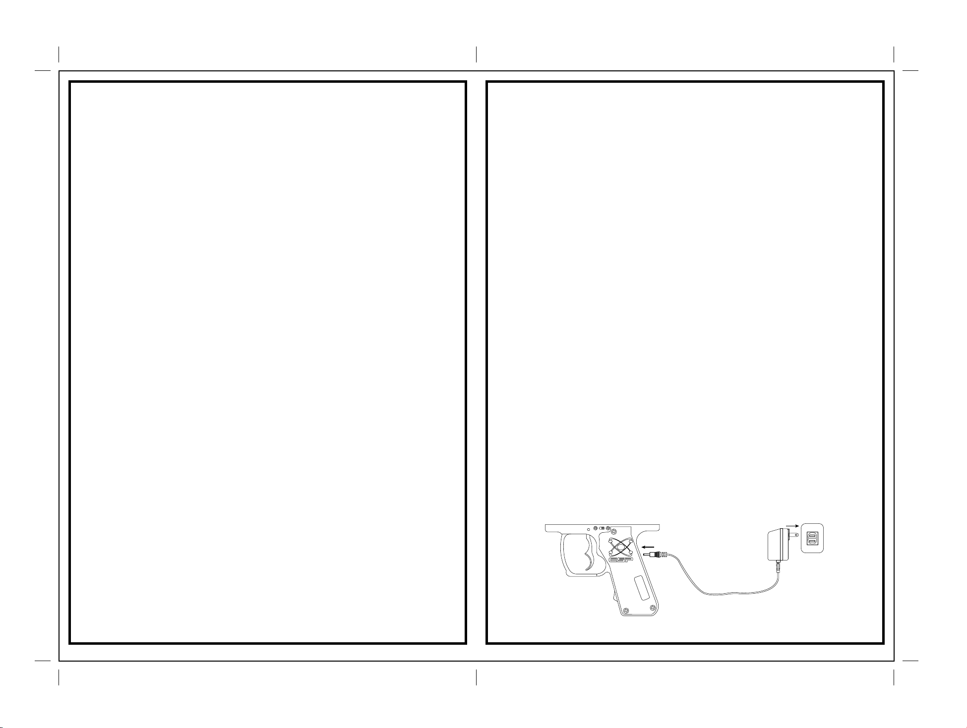
Remove the left E-Marker grip cover (part#22321). The battery terminal is located to the left
of the circuit board. Attach the battery to the battery connectors by aligning the + (positive)
on the battery connector to the + (positive) on the battery.
THE CHARGER FOR THIS BATTERY
This charger is specially designed for a 9.6Volt rechargeable battery. Five types of
chargers will be available from your Kingman Dealer:
1. Java Rapid Standard Indoor 110v A/C Charger (#JE1026)
2. Java Rapid Car Charger (#JE1022)
3. Java Standard Indoor 110v A/C Charger (#JE1024)
4. Java Standard 2B Indoor Charger (#JE1023)
5. Java Standard Indoor 220v A/C Charger (JE1025)
Using a Rapid Charger it will take approximately one and a half hours to fully charge the
JAVA 9.6 battery. It will take approximately 5-6 hours for the standard chargers.
WARNING
Using other unspecified batteries or chargers can cause damage to the circuit board. This
will void all warranty and liability from Kingman. Please use only Java 9.6 volt NiMH
rechargeable battery (Part # JE1015) and Java chargers.
RECHARGING THE BATTERY AFTER INITIAL USE
A fully charged battery will provide about 8000-12000 shots in normal use. The actual shots
will depend on the markers and the type of use. Due to the characteristics of the NiMH
battery, it won't be necessary to completely drain the battery before recharging it. So, you
can charge the battery any time you want and the time needed to the full charge will
depend on how much energy is left in the battery. The more energy left in the battery,
the sooner it will achieve a full charge.
P4 P5
Page 5
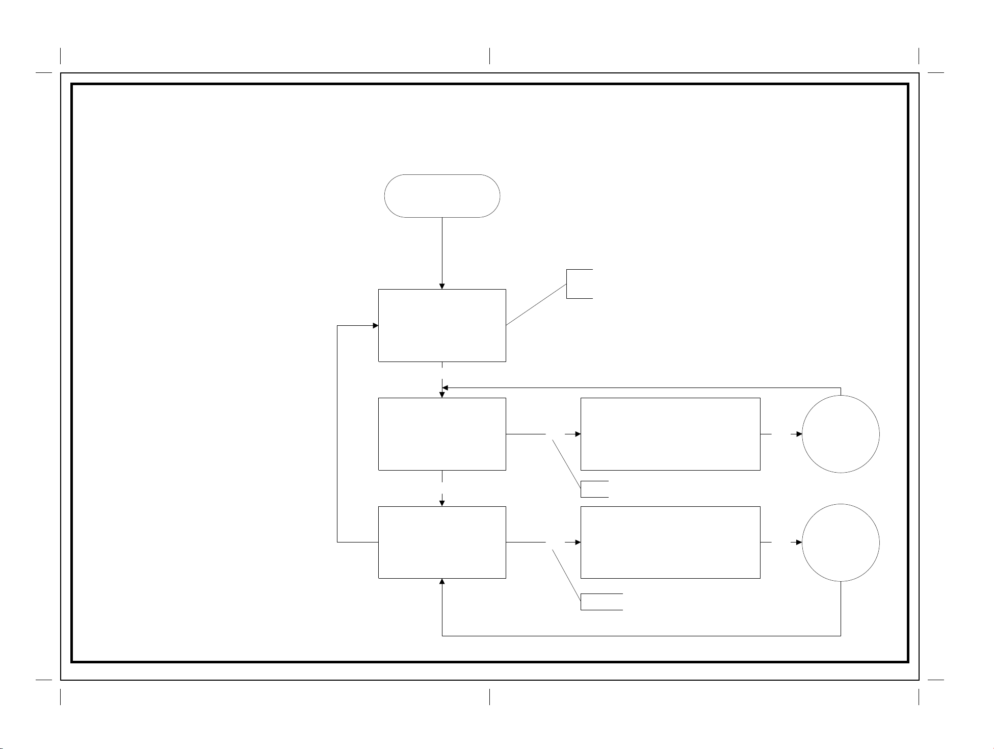
I.P.I 3.0 ( Intellig ent Push ke y Indicator - 3.0 )
Specifications & Operation Dia gram
Operation Methods:
1. The new I.P.I-3.0 has one push key for adjustment and 6
high efficiency LEDs for indicator. Three 5mm LEDs stands
for "MODE©, and two 3mm LEDs stands for "R.O.F". There
is also another one single 3mm red color LED for "Battery
Low" indicator.
2. For "MODE" indicator, there will be 3 colors can be
displayed, they are "Blue ", "Green" and "Red". The
meaning of colors are as follows:
(a). Blue SEMI , near the botttom.
(b). Green Burst-3 , on the middle.
(c). Red FULL . near the trigger.
3. For "R.O.F." Indicator, there are only 2 colors can be
displayed, they are "Orange" for low rate, and "White" for
high rate. For "Burst-3" and "FULL" mode, the "R.O.F"
can be toggled on "High" and "Low". But for "SEMI"
mode, the "R.O.F" indicator will be fixed on "High" for
reactive trigger response up to 14 shots per second.
4. When Power turns ON, the defaults will be Mode
="SEMI" and "R.O.F" = "High". All settings can be
adjusted while power keeps ON. Any adjustments will
be lost when Power turns OFF.
Click
Power ON
SEMI
MODE display "Blue"
ROF display "White"
Click
Burst 3
MODE display "Green"
ROF display unchanged
Press, Push and hold the key for over
2 seconds, then release the key.
Click, Push and then release the
key. The duration should be less than 1
seconds.
For SEMI Mode, the ROF
can not be adjusted.
NOTES:
During the interval of ROF Adjustment, the SAFETY will be
turned ON automatically, that is, trigger will be disabled on
this interval. The SAFETY will be turned OFF automatically
at the end of ROF Adjustment, then the trigger will be
functioning normally.
ROF Adjustment
ROF Indicator flashes, one click, it will
Press
be changed from "White flash" to
Press
"Orange flash". Click once more, it will
be changed to "White flash" again.
End of ROF
Adjustment
5. The "Battery Low" Indicator will remain OFF during
normal operations. When the capacity of battery
drops to about 1/3 of the battery full capacity, this
indicator will turn ON.
6. The I.P.I - 3.0 also equipped with a "LOCK" function.
A short-circuit plug located on the internal circuit board serves
this function. When this plug had been pulled out, the MODE
will be locked to SEMI, and cannot be adjusted.
P6
Click
FULL
MODE display "Red"
ROF display unchanged
Press
Mode Indicator display "Green"
ROF Adjustment
ROF Indicator flashes, one click, it will
be changed from "White flash" to
"Orange flash". Click once more, it will
be changed to "White flash" again.
Mode Indicator display "RED"
P7
Press
End of ROF
Adjustment
Page 6

NOTICE:
I. TROUBLESHOOTING
It is recommended that the battery be charged prior to use to ensure the maximum
capacity if you leave the battery unused for over a week.
LIFE OF BATTERY
With the qualified Charger, and in normal use conditions, about 700 – 1000 chargerecharge cycles can be expected. This be varied depending on the type of use.
GENERAL MAINTENANCE
1. Use compressed air to clean the coil set after every use (part no. #JE18C) to maintain
performance.
2. Beside step (1), cleaning should only be performed on the exterior of the E-Marker
frame. Never submerge the E-Marker frame in any type of liquid for any reason. The
electronics may become damaged or destroyed. Keep water or cleaning solution from
entering the inside of the E99 Avant frame. Solvents should not be used to clean any part
of the E99 Avant frame.
3. Always use the appropriate tool to remove screws and other components of the E99
Avant frame.
4. DO NOT DRY FIRE.
TOURNAMENT MODE SETTING
ONE OR MORE OF THE FOLLOWING MAY CAUSE RECOCKING RELATED
PROBLEMS:
a. The pressure in the tank is too low or too high.
b. Need lubrication. (See OPERATION GUIDE in P4)
c. #19A (striker o-ring) is damaged. Replace with new Kingman or Kingman-approved
o-ring. (NOTE: the #19A O-ring cannot be substituted by a tank o-ring or a #9 o-ring).
d. Need to clean barrel and upper chamber or the receiver.
e. Paintball may be defective (i.e. expired, change shape)
f. #9 (bolt o-ring) is damaged or the o-ring has expanded or swelled.
Replace with a new o-ring.
g. After ball breaks, remove all parts from UPPER chamber of receiver, wipe parts clean,
and reassemble parts into receiver. Also make sure to clean barrel with squeegee.
II. HELPFUL HINTS
Always remove air tank before any disassembly of your marker. DO NOT remove #14
(valve body) unless specific valve body repairs are needed. If needed, remove valve body
with a long, soft-tipped object such as the eraser end of a pencil. DO NOT remove the
valve body with a screwdriver as it will damage the valve body and cause air leaks. (Note:
#15 screw must be removed prior to taking out the valve body).
Air leaks are usually cause by a damaged valve body or damaged cup seal (#12). Replace
with new valve body and/or cup seal if necessary.
To assure marker is assembled properly, follow the schematic drawing or place parts in
order during disassembly. Parts assembled backwards or placed in the wrong order will
cause marker to malfunction.
The E99 Avant circuit board – (IPI 3.0) part no. JE28N also equipped with a “LOCK”
function. A short-circuit plug (JE30B) located on the internal circuit board serves this
function. When this plug had been pulled out, the MODE will be locked to SEMI, (single
shot mode) and cannot be adjusted. Putting the lock switch (JE30B) back into the circuit
board will enable the multi-mode functions. IMPORTANT! For optimal performance,
Kingman recommends that an agitator loader or hopper be used in order to shoot at high
rate of fire. Kingman also recommends to use JAVA CO2 Air Tank or High Pressure Air
Tank and tournament grade paint.
P8 P9
III. ELECTRONIC GRIP TROUBLESHOOTING
a. Check to make sure there is enough air pressure to fire the marker.
b. Battery may need to be recharged.
c. Specific troubleshooting questions may be answered by calling toll free at
(888) KINGMAN or (626) 430-2300.
Page 7
WARRANTY STATEMENT
Kingman warranties to the original customer purchaser that this product is free
from defects in material and workmanship under normal use and service for a
period of 12 months from the original date of purchase by the initial
owner/purchaser. For warranty to be effective, customer must return the enclosed
warranty registration card, along with a copy of the purchase receipt, within fifteen
days of purchase. Kingman agrees to repair or replace (at its discretion) any
product within a reasonable period of time. This warranty does not cover orings, 9.6v rechargeable battery, charger, scratches, nicks, normal wear and tear
of parts, any modifications or normal fading of anodizing or damage caused by
dropping or hitting of products. This warranty shall not apply if it is shown by
Kingman that the consumer caused the defect or malfunction because of misuse.
This warranty only covers original factory parts. Any modifications or tampering of
original factory parts will not be covered by this warranty. Any damage caused by
water will not be covered by this warranty. Warranty work can only be conducted
by Kingman technician or Kingman authorized technicians. If product needs
repair, package it carefully and send together with your name, address, phone
number and a brief description of the malfunction to:
KINGMAN GROUP
14010 Live Oak Avenue
Baldwin Park, CA 91706 U.S.A.
KINGMAN GROUP Warranty Registration
PLEASE COMPLETE AND RETURN THIS FORM, ALONG WITH
A COPY OF YOUR PURCHASE RECEIPT, WITHIN 15 DAYS OF
PURCHASE SO THAT WE MAY VALIDATE YOUR ONE YEAR
LIMITED WARRANTY.
Mail to: Kingman Group
14010 Live Oak Avenue,
Baldwin Park, CA 91706 U.S.A.
Name Telephone ( )
Address
City State Zip Country
Your age E-mail address Occupation
Product name and model
What other brand(s) of markers do you own?
Why did you purchase this Kingman marker?
Avg # of times you play paintball per month
What is the next paintball product you intend to buy?
What are your hobbies (other than paintball)?
Phone no.: 626.430.2300
Fax no.: 626.851.8530
Website: www.kingman.com
What are some magazines you like to read?
Have you purchased products from the Internet within the last 6 months?
Comments/Suggestions:
14010 Live Oak Avenue, Baldwin Park, CA 91706 USA
Telephone:(626)430-2300 Fax:(626)851-8530
Website: www.kingman.com
P10 P11
 Loading...