


Spy®
model 670
po rtab le wet sponge
h o l i day detector
o p e r at i n g
instructions
PIPELINE INSPECTION COMPANY
picltd.com

2
pi clt d.co mpi clt d.co m
3
welcome
Thank you for purchasing the SPY® Model 670 Wet Sponge Holiday
Detector.
Pipeline Inspection Company and our SPY
®
brand of coating inspection,
jeep meter and pig tracking equipment has been serving companies all
over the world for over 60 years. With the purchase of this high precision
instrument you can now enjoy access to worldwide service and support
only SPY® and our vast Distributor network can offer.
For more information about SPY® brand equipment please visit our
website at picltd.com.
Tab le of contents
Unit Calibration . . . . . . . . . . . . . . . . . . . . . . . . . . . . . . . . . 4
Principles of Wet Sponge Holiday Detection . . . . . . . . . . . . 5
670 Overview . . . . . . . . . . . . . . . . . . . . . . . . . . . . . . . . 6
Connecting Accessories . . . . . . . . . . . . . . . . . . . . . . . . . . 8
Connecting Optional Accessories . . . . . . . . . . . . . . . . . . . . . 10
Battery Instructions . . . . . . . . . . . . . . . . . . . . . . . . . . . . 11
Controls & Testing Instructions . . . . . . . . . . . . . . . . . . . . . . 12
670 Operation . . . . . . . . . . . . . . . . . . . . . . . . . . . . . . . . . . 13
Troubleshooting Guide . . . . . . . . . . . . . . . . . . . . . . . . . . . . . . 15
Technical Specifications . . . . . . . . . . . . . . . . . . . . . . . . . . . . 18
Maintenance & Repair . . . . . . . . . . . . . . . . . . . . . . . . . . . . 19
Warranty . . . . . . . . . . . . . . . . . . . . . . . . . . . . . . . . . . . . . . 20
Electrode Types . . . . . . . . . . . . . . . . . . . . . . . . . . . . . . . . 21
Accessories . . . . . . . . . . . . . . . . . . . . . . . . . . . . . . . . . . 22
Related Equipment . . . . . . . . . . . . . . . . . . . . . . . . . . . . . 23
Wet Sponge Inspection Kit . . . . . . . . . . . . . . . . . . . . . . . . 24
The SPY® Model 670 Holiday Detector meets the Electromagnetic
Compatibility and Low Voltage Directive. This product is a Class B,
Group 1 ISM equipment according to CISPR 11. Group 1 ISM product: A
product in which there is intentionally generated an d/or used conductively
coupled radio -frequency energy which is necessary for the internal
functioning of the equipment itself. Class B products are suitable for use
in domestic establishments and in establishments directly connected to
a low voltage power supply network which supplies buildings used for
domestic purpose.
is a registered trademark of Pipeline Inspection Company,
Houston, Texas 77055, United States.
A copy of this Operating Instructions Manual can be downloaded on our
website at picltd.com.

4
pi clt d.co mpi clt d.co m
5
unit calibration principles of wet Sponge
h o l i day detection
As the operator of this unit you require accurate, safe, and reliable equipment to
perform coating inspections at the proper output voltage.
Prior to leaving our manufacturing facility Pipeline Inspection Co. certifies
that SPY
®
Model 670 Wet Sp onge Holiday Detectors has b een calibrated and
demonstrates the ou tput voltage of 67.5 volts (+/- 5%). Since output voltage is
regulated, this toler ance is maintained regardless of load.
Your unit comes with a Factory Calibration Certificate and a Factory
Authorized Calibration Decal applied to the bottom of the unit both with the
date your unit was calibrated.
Our units do not tend to drift but it is recommended that this unit be calibrated at
least once per year or more frequently based on heav y usage. Recal ibration of
our equ ipment should be perfo rmed ONLY at a SPY
®
Authorized Service
Cente r due to the uniq ue calibration proces s; test equi pment util ized and
prope rly trained SPY
®
technicians.
We DO NOT recommend using any other calibration ser vice other than a SPY
®
Authorized Ser vice Center; using an outside service with technicians not trained
to work on SPY
®
brand equipment could damage the unit and if the enclosure is
opened will void the warranty.
When calibration is needed please return your unit to a SPY
®
Authorized Service
Center or SPY
®
manufacturing facility located at:
Pipeline Inspection Company
Attn: Calibration
1919 An toine Dr.
Houston, T X 77055
Please include: Company Name and Contac t Information. For a complete list of
Authorized Ser vice Centers please visit our website at picltd.com. If a copy of the
Calibration C ertificate on file is needed it may be obtained by emailing a request to
sales@picltd.com.
Wet Sponge Holiday Detectors are used for the detection of discontinuities
(holidays) in thin film coatings (1-20 mils) of paint, epox y or any non-con ductive
material applied to a conductive material. This t ype of detector uses 67.5 volts
DC for a test voltage, w hich is applied to the test surfac e via a wet sponge. The
fluid media (usually water) in the wet sponge fills the voids in the surface to be
tested and allows low current (micro-amps) to flow into any ho lidays in the test
area. The current moves through the holiday and into the conductive substrate
which activates a horn to indicate the presence of the holiday.

6
pi clt d.co mpi clt d.co m
7
670 overview
The NEW SPY Model 670 Wet Sponge Holiday Detector operates on a
single 9 volt alkaline battery. Unit output voltage is 67.5 volts DC. This
voltage makes the detector highly sensitive and accurate. Compact and
light weight with no bulky battery packs allowing for non destructive
inspection of paints, epoxy paints and coatings 1-20 Mils.
Inspect larger surfaces faster and with less operator fatigue using a
quick attach, easy to use roller sponge electrode. (Optional Accessory).
•
New Ergonomic, Balanced, Lightweight Hand held Design
•
New Rugged, Durable Construction
•
67.5 Volt DC, Sensitive and Accurate
•
New Quick Change Battery Compartment
•
A New Wide Range of Quick Change Accessories
•
New Inspections Kit w/Carrying Case (Optional)
1 Standard Large Sponge
2 Standard 14.5” Wand Shaft
3 Quick Connect Points for
Optional Accessories
4 Built-In 8 0Kohm and 100Kohm
Calibration Test Buttons
5 Water Proof Power Switch
6 Audible Holiday Indicator
7 Visual Holiday and Low Battery
Indicator
8 Shoulder Strap Connection
9 Quick Change Batter y
Compartment
10 Ground Cable Connection
9
10
3
3
5
6
7
8
4
2
1

8
pi clt d.co mpi clt d.co m
9
con necting accessories
STEP 3. CO NNECTING T HE GROUND CABL E. The ground cable at tach
point is on the backside of the 670, untwist the black knob to expose the hole in
the ground connector, thread the ground wire through the hole and then tighten the
black ground connector knob tightly with your hand only.
CAUTION! DO NO T TOUCH Make sure the switch is in the OF F position
prior to connecting any accessory.
STEP 1. CONN ECTING THE E LECTRODE WAND. Screw the wand onto the
base of the 670 holiday detector and firmly tighten with your hand only.
STEP 2. CO NNECTING T HE ELECTROD ES. The flat sponge ele ctrode comes
standard with t he 670 and is already attac hed to the wand. However, if you purchased
the optional roller sponge electrode just unsc rew the flat sponge electrode from the
top of the wand and screw on the optional roller sponge elec trode. You can adjust
the flat sponge o r roller sponge electrode by simply holding the knurled k nob firmly
and twisting the electrode to the desired position.
CAUTION! DO NO T TOUCH THE ELECTRODE WHILE T HE DETECTOR
IS OPERATING.
CAUTION! DO NO T TOUCH THE ELECTRODE WHILE T HE DETECTOR
IS OPERATING.
PROPER GROUNDING. Make sure the ground c able is uncoiled and
extended.
DIAGRA M 1: Shows the method of completing a circuit is by connecting
the ground cable of the 670 holiday detector to the unco ated part of the metal
substrate of the test piece using the alligator clip. This allow s the circuit to
complete directly from the detector through the holiday into the substrate back
into the detec tor.
1
2
3
DIAGRAM 1
WET SPONGE GROUND
CABLE
METAL
NON-CONDUCTIVE
COATING
ALLIGATOR
CLIP
PINHOLE
HO LIDAY

10
pi clt d.co mpi clt d.co m
11
battery
Instructions
connecting optional
accessories
For a range of optional accessories and spare parts that enhance and
expand the capabilities of the SPY 670 SPY offers an Optional 670
Inspection Kit. See the Accessories page in this manual or call your SPY
distributor or manufacturer to order.
STEP 5. (OPT IONAL) CONNECTING THE SHOULDER STRAP.
Attach the strap clips tabs on each side of the 670 detector. Adjust strap
for comfort. The strap comes with the optional 670 Inspection Kit which
offers the option of attaching a light weight foam handle wand to use
while operating rather than holding the weight of the complete unit.
STEP 6. (OPTIONAL) CONNECTING ADDITI ONAL 14.5”
WAND EXTENSION RODS. With the 670 turned off simply unscrew
the electrode from the wand and screw on the number of 14.5” wand
extensions you need for the job, once complete add the electrode back
to the end of the wand. The optional 670 Inspection Kit comes with
2-14.4” wand extensions to give the 670 detector added length for hard
to reach test areas
STEP 7. (OPTIONAL) CONNECTING WAND LEAD CABLE.
With the 670 turned off disconnect the wand from the base of the unit,
screw the knurled portion knob of the wand lead cable to the base of the
unit and plug the other end of the wand lead cable to the end of the foam
handle wand. Unscrew the electrode from the stock wand electrode and
screw it on the foam hand wand.
The NEW SPY® Model 670 Wet Sponge Holiday Detector operates on
a single 9 volt alkaline battery. Unit output voltage is 67.5 volts DC. This
voltage makes the detector highly sensitive and accurate.
STEP 1: Make sure the detector switch is in the off position.
STEP 2: The battery compartment is located on the left side of the unit,
using the notch on the bottom of the batter y compartment lift up and
pull out to slide the battery tray out.
STEP 3: Insert a new 9V battery into the battery tray and push the
battery tray firmly back into the unit making sure it locks back into place.
If the battery discharges to a low level the detector will begin to tone
continuously, at this point the detector is not properly detecting holidays
and the battery should be changed to a new 9V battery.
Low Battery

12
pi clt d.co mpi clt d.co m
13
controls
testing
instructions
No Signal adjustment is necessary with the 670 Wet Sponge Holiday
Detector. The unit can easily be tested by means of the test buttons
located on the front operating panel.
The test is performed by turning the 670 on and by pressing the 80 Kohm
button, the signal will become active causing the horn and LED to be
activated. Release the 80 Kohm button then press the 100 Kohm, the
signal should NOT activate the horn and LED. This test indicates the unit
sensitivity is within calibration.
670 operation
STEP 1: Insert a new 9V battery in the battery box and push the
battery box firmly back into the unit making sure the battery box locks
back into place.
STEP 2: Attach the electrode wand and electrode.
STEP 3: Attach the ground cable to the conductive substrate of the test
surface (the uncoated bare metal portion of the surface). See Diagram
1 on page 8.
STEP 4: Wet the electrode sponge with clean tap water to where it is
damp or moist to the touch and apply SPY
®
wetting agent.
STEP 5: Keeping the detector away from the test surface and turn the
detector to the on position.
IMPORTANT! While the electrode sponge must be damp or
moist to the touch it should not be saturated to the point water
is running from the sponge. This can result in the water migrating and
causing the current to flow away from the sponge down the test surface
to holidays further down the test sur face or even on the support surface
causing false holiday indications.
IMPORTANT! When the coating thickness is between 11– 20
mils, a low sudsing wetting agent such as KODAK Photo-flo
™
should be applied to the water (test media). This will allow for a lower
surface tension, which will help the test media to penetrate the thicker
coatings. You can order Kodak Photo-flo
™
direct from SPY®.

14
pi clt d.co mpi clt d.co m
15
STEP 6: Place the electrode sponge on the coated surface and begin
passing the sponge across the surface (See Diagram 2 Below). Several
passes should be made over the test area to ensure that moisture has
penetrated any possible holiday. If the sponge passes across a pinhole
in the coated surface an audible horn from the detector will begin to
sound and the red light on the control panel will light up. The audible
and visual alert will stop once the electrode moves away from the
pinhole. For more precisely locating the holiday use the corner of the
sponge in the area the holiday occurred.
IMPORTANT! Care should be made to ensure that the sponge
stays as clean as possible. Dirt or other contamination of the test
surface adds resistance, which impedes the current flow capability of
the sponge. This can result in missing holidays in the test piece.
troubleshooting guide
PROBLEM POSSIBLE SOLUTION CORRECTION MET HOD
HOLIDAY
DETECTOR
WILL NOT
DETECT
HOLIDAY S
Test Buttons Push the 80k test button,
the horn should sound.
Push the 100k test button,
the horn WILL NOT sound.
Detection Testing Touch electrode/wand
directly to bare ground
cable to test that the unit is
functioning properly.
The horn will sound and the
light on the control panel
will light up.
If the detector does not
detect then ensure ground
cable and electrode wand
are correctly connected.
If the detector still fails
to detect a defect in the
coating a repair may be
needed, contact Pipeline
Inspection Company for
support.
TROUBL ESHOOTING G UIDE CONTIN UED ON THE NE XT PAGE...
DIAGRAM 2
CONNE CT GROUND CA BLE TO UNCOATED ME TAL SUBSTR ATE.

16
pi clt d.co mpi clt d.co m
17
troubleshooting guide troubleshooting guide
PROBLEM POSSIBLE SOLUTION CORRECTION MET HOD
HOLIDAY
DETECTOR
WILL NOT
DETECT
HOLIDAY S
Check Detector Ground
Connection
With the detector OFF
remove the ground
cable, clean banana plug
connection point and
reconnect ground.
Ensure both ends of the
ground cable are clean.
Ensure the clip end of the
ground cable is securely
connected to metal
substrate.
Check Electrode/
Wand Connection
With the detector OFF
unscrew the wand,
clean connections and
reassemble.
Ensure wand and electrode
connection points are clean.
PROBLEM POSSIBLE SOLUTION CORRECTION MET HOD
DETECTOR
HORN
CONSTANT
SOUND
Check Battery When the battery is
low the horn will sound
continuously to let you
know it needs to be
replaced. Replace with
new battery.
Test Buttons Stuck Check that the test buttons
are not stuck by pressing
each several times to
disengage.
DETECTOR
DOES NOT
TURN ON
Switch Check the power switch to
make sure its full toggled
on.
Battery Batter y is low. Replace
battery.

18
pi clt d.co mpi clt d.co m
19
technical
specifications
If maintained the Model 670 Wet Sponge Holiday Detector will offer you
years of dependable operation. Regular care and maintenance of the unit
is a requirement of good quality preventative maintenance practices.
WARN ING! This detector does not contain any user-serviceable
parts; your warranty will be voided if the SPY
®
unit is opened
by anyone other than a SPY
®
Authorized Service Center or SPY®
manufacturing facility.
In the event the unit fails to operate properly please return your unit to a
SPY Authorized Ser vice Center or SPY manufacturing facilit y located at:
Pipeline Inspection Company
Attention: Repair
1919 Antoine Dr.
Houston, Texas 77055
Please include: Company name, contact information and a short
description of the problem with the unit. For a complete list of
Authorized Service Centers please visit our website at picltd.com.
ELECTRODES AND ACCESSORIES
Sponge electrodes and all attached accessories are prone to wear and
tear and will eventually need to be replaced, timing of replacement
will depend on how they are maintained and the coatings that they are
used on.
maintenance & repair
MODEL 670
Voltage Type DC
Voltage Range (k V) 67.5 Volts
Voltage Output Accuracy ±5%
Coating Rang e (Min-Max ) 1 - 20 mils
Operating Temperature 33°F to 148°F
Holiday Indic ator Type Audible/Visual
Battery 9 Volt Battery
Battery L ife 8-12 Hours
Low Battery Indicator Yes
Unit Weight Only 0.9 lbs
Unit Weight With Battery Only 1.8 lbs
Unit Dimensions (LxWxH) 9” x 4.5” x 3.25”
With Wand 25” x 4.5” x 8”
Domestic/International Standards NACE SP0188 -2006
Unit Complies W ith
Factory Warranty 3 Month

20
pi clt d.co mpi clt d.co m
21
Pipeline Inspection Company, hereafter referred to as (SPY®) warrants
that SPY
®
‚ Model 670 Series Holiday Detectors shall, under normal use
and service, be free from defects in material and workmanship. SP Y
®
‘s
entire warranty oblig ation shall be limited to, at SPY
®
’s option, the repair or
replacement free of charge to the buyer of any defective equipment or parts
thereof which prove to be defective in material and workmanship under
normal use and ser vice.
Claims for defective par ts must be made in writing within three (3) months
after shipment of the equipment from the works of SPY
®
. Fast wearing and
consumable par ts including, but not limited to, electrodes and ground cables,
are expressly excluded from the warranty. SPY
®
shall have the option to
require return of a claimed defective part to SPY
®
’s manufacturing facility in
the U.S.A ., freight prepaid by buyer for examination to establish buyer’s claim.
Except with SPY
®
’s prior written approval, SPY® shall not be liable (a) for
the cost of repairs, alterations or replacements or any expense connected
therewith made or incurred by the buyer or its designers, or (b) for defects
resulting from alterations or repairs made by others than SPY
®
‚ or its
approved representatives.
SPY
®
shall not be liable for dam ages, including but not limited to direct , special,
indirect or consequential, resulting from the handling, or use, whether alone
or in combination with other products, or any SPY
®
equipment or third par ty
designed or manufactured equipment, including without limitation, any loss
or damage sustained or caused by the operation and use of the equipment
which is improperly operated or its successful operation is impaired by
natural elements after its delivery to the buyer.
The foregoing warrant y is exclusive and in lieu of all other warranties
whether written, oral or implied (including without limitation, any warranty
of merchantability or fitness for purpose).
warranty
FL AT SP ONG E
3” X 2” X 2”
INTERNAL SPONGE
2”- 28” (5 0–711mm)
ROLLER SPONGE
INTERNA L
SPONGE PU LL
CABLE
Electrode types
The Model 670 uses cellulose sponge electrodes that vary in form and
size and fit a wide range of coating inspection projects. If we don’t carry
it we can custom build an electrode to fit your project needs.
Different types of electrodes can be used with different units. The most
common electrode is a flat sponge electrode wand. The Model 670
wand utilizes a 2”x 4” x 8” (51mm x 102mm x 203mm) size flat sponge.
Roller sponges are also available to increase the surface area in contact
and the speed at which the test piece can be tested.
Please call our office at (713) 681-5837 or email us at sales@picltd.com
for more product details or to place an order.
IMPORTANT! SPY uses ONLY cellulose sponges for our wet
sponge units. DO NOT use rubber or urethane sponges!

22
pi clt d.co mpi clt d.co m
23
accessories
The Model 670 has a wide variety of accessories to assist you with your
coating inspection project.
Please call our office at (713) 681-5837 or email us at sales@picltd.com
for more product details or to place an order.
related equipment
GROUND CABLE
(2 5 FT. )
ITEM #11927
SHOULDER
STRAP
ITE M #10187
16 OZ. BOTTLE O F
WET TING AGENT
ITE M #1400 1
ROLLER SPONGE
WAND
ITE M #14160
4 OZ. BOTTLE O F
WET TING AGENT
ITE M #1398 5
14.5” EXTENSION
ROD FOR WAND
ITE M #14162
SPY
®
MODEL 673
WET S PONGE
DETEC TOR
FL AT SPO NGE
WAND
ITE M #14159
ROLLER SPONGE
REPLAC EMENT
PACK S
AVAIL ABLE IN
PACKS O F 3, 5 OR 7
Please call our office at (713) 681-5837 or email us at sales@picltd.com
for more product details or to place an order.
24
pi clt d.co mpi clt d.co m
25
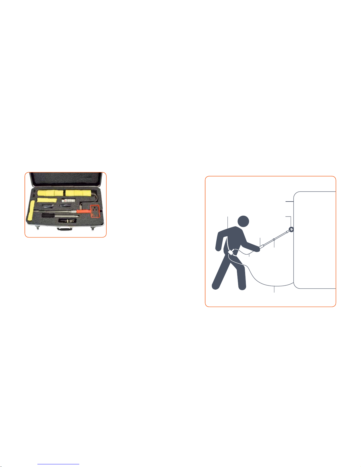
wet sponge inspection kit optional 670 inspection kit
For added operator comfort & inspection capability
KIT INCLUD ES:
1 - CAR RYING/SHI PPING CASE
1 - ROLL ER SPONGE AXL E
3 - SPARE RO LLER SPONGES
2 - 14.5” EX TENSION SHA FTS
1 - SPARE FL AT SPONGE
(4” X 8” X 2”)
1 - 35FT G ROUND CABLE
1 - FOAM WAND H ANDLE
1 - WAND SIGN AL CABLE
1 - 4OZ. WE TTING AGENT
2 - 9 VOLT BATTERI ES
1 - SHOULD ER STRAP
ITE M #670 KIT (DE TECT OR NOT
INCLU DED)
Foam Grip Wa nd
Handle for Ad ded
Comfort
Any La rge
Coated Surface
12” Roller Spong e
to Reduce Surface
Resistance
2 - 14.5” Add- On
Extensions for
Added Reach
35’ Ground C able to Help Inspect
Larger Co ating Areas
Wand Signal
Cable
Adjustable Shoulder
Strap to Carr y 670
and Reduce Operator
Fatigue

26
pi clt d.co mpi clt d.co m
27
User Notes User Notes

PIPELINE INSPECTION COMPANY
picltd.com
 Loading...