

SPX POWER TEAM 3S-6224, 65804, PA550, X1A1, 8S-8033 Operating Instructions Manual
...
SPX Hydraulic Technologies
5885 11th Street
Rockford, IL 61109-3699 USA
powerteam.com
Tech Services: +1 800 477 8326
Fax: +1 800 765 8326
Order Entry: +1 800 541 1418
Fax: +1 800 288 7031
AIR, ELECTRIC, OR GAS-POWERED
TWO-STAGE HYDRAULIC PUMP
5,000 OR 10,000 PSI
Operating Instructions for:
3S-6224 65804 PA550 X1A1
8S-8033 66027 PA90A X1E1
110-000251E-* 66027-230 PE55 SERIES X1E1-TDS
4060 SERIES 66105 PE90 SERIES X1E1C
4070 100220 PE120M X1E2
4080 SERIES 100220-230 SERIES X1E3
60014-AMP AHC-10E PG55 SERIES Y26 SERIES
60018-AMP EP-720-G PLA6014 Y60 SERIES
60208 EP-720-G-230 PLE6014 Y70 SERIES
61217 HWP*-JR PLE6014-220 X1A1-PT
61217-50-220 JT07192 RSST-20 X1E1-PT
61217-575 NTW-HPE310 SST-200T
© 2014 SPX CORPORATION
1
Form No. 102463
Rev. 9 February, 2015

CONTENTS
SAFETY DEFINITIONS 3
SAFETY PRECAUTIONS 3
HYDRAULIC PUMP SET-UP PROCEDURE 7
1. Motor Hook-up and Operation 7
2. Electric line connection (for electric motor units only) 7
SET-UP AND OPERATION 9
1. Filling The Reservoir 9
2. Hydraulic Connections 10
3. Valve Options 10
4. Hydraulic Gauge (Optional) 10
5. Adjusting The Hydraulic Gauge 12
6. Reservoir Vent Air Filter (Optional) 12
7. Priming The Pump 12
8. Adjusting The Pressure Regulating Controls 13
9. Adjusting The Pressure Regulating Valve 13
10. Adjusting The Pressure Switch 14
PREVENTIVE MAINTENANCE 15
1. Bleeding Air From The System 15
2. Hydraulic Fluid Level 15
3. Lubrication (Air Driven Motor Only) 15
4. Maintenance Cleaning 15
5. Draining And Flushing The Reservoir 16
6. Adding Oil To The Reservoir 16
7. Sound Reduction 17
8. Checking Brushes On Universal Motors 17
REASSEMBLY SPECIFICATIONS 17
NEEDLE BEARING INSTALLATION SPECIFICATIONS 18
TROUBLESHOOTING GUIDE 18
POWER TEAM FACILITIES 23
DECLARATION OF INCORPORATION 24
© 2014 SPX CORPORATION
2
Form No. 102463
Rev. 9 February, 2015
SAFETY DEFINITIONS
Safety symbols are used to identify any action or lack of action that can cause personal injury.
Your reading and understanding of these safety symbols is very important.
DANGER
Danger is used only when your action or lack of action will cause serious human injury or
death.
WARNING
Warning is used to describe any action or lack of action where a serious injury can occur.
DANGEROUS VOLTAGE
Dangerous Voltage is used to describe any action or lack of action that could cause serious personal injury or death from high voltage electricity.
CAUTION
Caution is used when action or lack of action can cause equipment failure, either immediate or over a long period of time.
SAFETY PRECAUTIONS
To help prevent personal injury,
HYDRAULIC HOSE
• Before operating the pump, all hose connections must be tightened with
the proper tools. Do not overtighten. Connections should only be tightened
securely and leak-free. Overtightening can cause premature thread failure or
high pressure ttings to split at pressures lower than their rated capacities.
• Always shut off the electric motor before breaking any connections in the
system.
• Should a hydraulic hose ever rupture, burst, or need to be disconnected,
immediately shut off the pump. Never attempt to grasp a leaking pressurized
hose with your hands. The force of escaping hydraulic uid could cause
serious injury.
• Do not subject the hose to potential hazard such as re, sharp surfaces,
extreme heat or cold, or heavy impact. Do not let the hose kink, twist, curl or
bend so tightly that oil ow within the hose is blocked or reduced. Periodically inspect the hose for wear, because any of these conditions can damage the hose.
WARNING
• Do not use the hose to move attached equipment. Stress can damage the
hose, causing personal injury.
© 2014 SPX CORPORATION
3
Form No. 102463
Rev. 9 February, 2015
• Hose material and coupler seals must be compatible with the hydraulic uid
used. Hoses also must not come in contact with corrosive materials such as
creosote-impregnated objects and some paints. Consult the manufacturer
before painting a hose. Never paint the couplers. Hose deterioration due to
corrosive materials can result in personal injury.
PUMP
• Do not exceed the PSI hydraulic pressure rating noted on the pump nameplate
or tamper with the internal high pressure relief valve. Creating pressure beyond rated capacities can result in personal injury.
• Before replenishing the oil level, retract the system to prevent overlling the
pump reservoir. An overll can cause personal injury due to excess reservoir
pressure created when the cylinders are retracted.
CYLINDER
• Do not exceed the rated capacities of the cylinders. Excess pressure can result
in personal injury.
• Do not set poorly balanced or off-center loads on a cylinder. The load can tip
and cause personal injury.
POWER SUPPLY (Electric)
• Never use an ungrounded power supply with this unit.
• The pump must be compatible with existing line voltage.
• Disconnect the pump from the power supply when performing maintenance or
repair on the unit.
• If the unit’s power supply is damaged or the inner wiring is exposed in any
way, replace immediately.
• Any electrical work must be done by a qualied electrician.
• If the power cord is damaged or wiring is exposed, replace or repair immediately.
• Changing the voltage on the jet motor (single, or three phase) is a complicated
and, if not done correctly, dangerous procedure. Consult the pump manufacturer’s Technical Services Department for specic information before attempting any rewiring. Rewiring voids CSA approval.
• All voltages must be wired for CW rotation when viewed from the lead end
(top) of the motor.
• Check the total amperage draw for the electrical circuit you will be using. (For
example: Do not plug a motor or motors that may draw 25 amps into a 20 amp
fused electrical circuit.)
• Do not attempt to increase the powerline capacity by replacing a fuse with
another fuse of higher value. Overheating of the powerline and the possibility
of a re will result.
• To rewire a motor from one voltage to another or when a ow control valve is
changed between manual and solenoid, consult the electrical schematic in the
pump’s parts list.
© 2014 SPX CORPORATION
4
Form No. 102463
Rev. 9 February, 2015

• Circuit Breakers: If motor stops due to an overload or power outage, Universal
Motor: Move motor switch to OFF and control valve to neutral. Let motor cool
or wait until power is restored. Reset circuit breaker switch in power panel.
(The pump motor doesn’t have a circuit breaker.) Single-phase Motor: Thermal
overload switch will break circuit to the motor. Move motor switch to OFF and
control valve to neutral. Allow motor to cool before switching on again, or wait
until power is restored. Three-phase Motor: A magnetic starter switch breaks
circuit to the motor. Move the motor switch to OFF and control valve to neutral.
Remove the cover on motor control box. Let the motor cool or wail until power
is restored. One of three reset buttons must be pushed in to reset motor. Replace cover.
Power Supply (Gasoline Engine)
• Read the instruction manual for the gasoline engine before using.
• Do not allow fuel to splash on the engine when refueling.
• Do not add fuel when the engine is running or very hot.
Power Supply (Air Driven Motor)
• Disconnect air supply when pump is not in use or when breaking any connection in the hydraulic system.
• A shut-off valve or quick disconnect should be installed in the air line to the
pump unit. Close the shut-off valve before connecting the air line to the pump.
© 2014 SPX CORPORATION
5
Form No. 102463
Rev. 9 February, 2015
NOTE
• Carefully inspect the pump upon arrival. The carrier, not the manufacturer, is responsible for any damage resulting from shipment.
• Read and carefully follow these instructions. Most problems with new equipment are
caused by improper operation or installation.
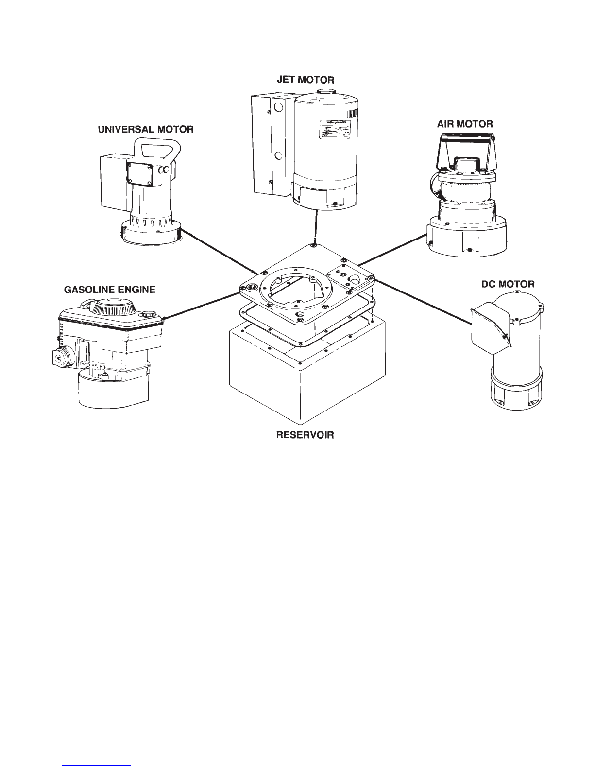
• The hydraulic power unit can be ordered with “building block” exibility. The customer
can choose from a variety of motors, controls, reservoirs, and other options. Because
of the many options available, these instructions will include directions for options that
your particular pump may not have.
• Do not change motors without consulting the pump manufacturer’s Technical Services
Department.
© 2014 SPX CORPORATION
6
Form No. 102463
Rev. 9 February, 2015

HYDRAULIC PUMP SET-UP PROCEDURE
1. Motor Hook-up and Operation
A. Universal Motor
The universal motor is wired for 115 or 230 volts, 50/60 cycles according to the customer’s
request. This motor cannot be rewired.
B. Jet Motor, Single-phase
The single-phase jet motor is wired for 115 or 230 volts, 50/60 cycles according to the
customer’s request.
C. Jet Motor, Three-phase
The three-phase jet motor is wired for 230 or 460 volts, 50/60 cycles according to the
customer’s request.
D. Gasoline-Powered
Consult the instruction manual for the gasoline engine.
E. Air Motor
Remove the thread protectors from the air inlet, and install the air supply ttings (not supplied) as shown in Figure 1. Air supply must be minimum 50 CFM and 80 PSI, with 100 PSI
maximum.
2. Electric Line Connections (for electric motor units only)
DANGER
Your pump comes equipped with a standard plug and cord and is appropriate for the
specied voltage of this pump (as identied on the product and package labeling). Before
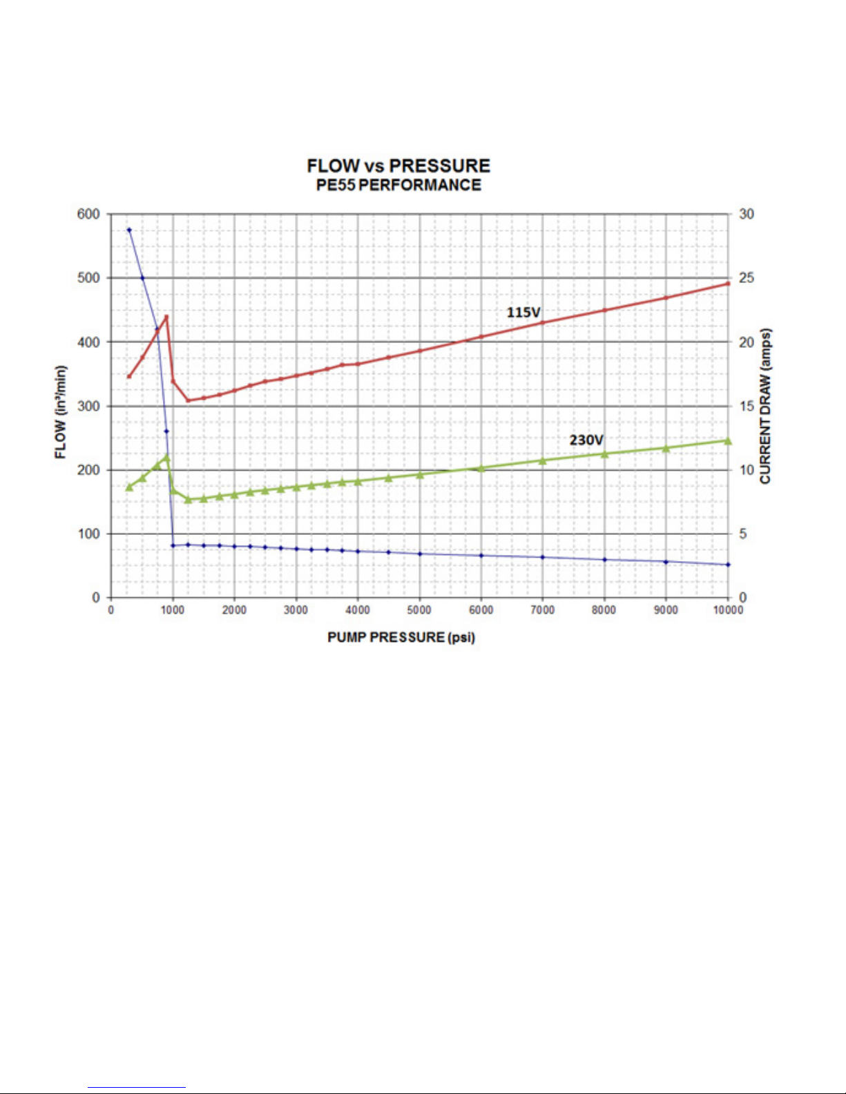
each use of the pump, the user must consult with the gure below in order to determine the
applicable current draw for each specic application and then must ensure that the
infrastructure of the facility in which the pump is to be used is suitable for safe operation of
this pump based upon the following guidelines:
A. Line circuit protection and disconnect are to be provided by the customer.
B. Line circuit protection is to be at least 115% of the full load current at the peak pressure
attained when the pump is in use (see gure below). Per the specic application.
C. Refer to the pump nameplate for additional information about the pump’s power rating.
D. Refer to the SAFETY PRECAUTIONS at the beginning of this manual before operation and
before making any modications.
MODIFICATIONS TO THE CORD AND/OR PLUG SHOULD ONLY BE DONE BY A QUALIFIED
ELECTRICIAN. IT IS THEIR RESPONSIBILITY TO ADHERE TO ALL LOCAL, STATE AND
FEDERAL CODES.
Alternative cord sets are available based upon your specic application requirements
(see gure below). Contact your local service center or distributor or www.PowerTeam.com for
details.
© 2014 SPX CORPORATION
7
Form No. 102463
Rev. 9 February, 2015
© 2014 SPX CORPORATION
8
Form No. 102463
Rev. 9 February, 2015
 Loading...