

Page 1
PORTA
LE AIR CO
B
NDI
IONER
T
S
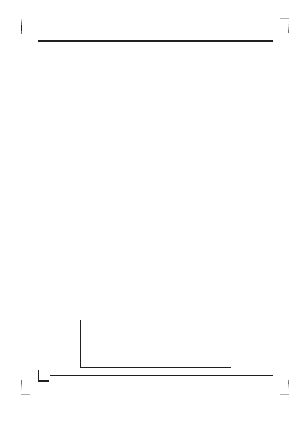
WA-1240E: 12,000 BTU Cooling only
WA-1240H: 12,000 BTU Cooling and Heating
WA-1420E: 14,000 BTU Cooling only
WA-1420H: 14,000 BTU Cooling and Heating
Inside you will find many helpful hints on how to use and maintain your air conditioner properly. Just
a little preventative care on your part can save you a great deal of time and money over the life of
your air conditioner. Before operating this product, please read the instructions carefully and save this
manual for future use.
Page 2
CONTENTS
SOCIABLE REMARK
Sociable remark..................................................................................................................................2
SAFETY PRECAUTIONS
Safety rules .......................................................................................................................................3
Operating condition ...........................................................................................................................3
Electrical information .........................................................................................................................4
IDENTIFICATION OF PARTS
Accessories .......................................................................................................................................4
Names of parts...................................................................................................................................5
AIR CONDITIONER FEATURES
Electronic control operating instructions ...........................................................................................6
OPERATING INSTRUCTIONS
Operating instructions .......................................................................................................................7
INSTALLATION INSTRUCTIONS
Location ............................................................................................................................................9
Window kit installation ......................................................................................................................9
Exhaust hose installation ................................................................................................................12
Though-the-wall connection ..............................................................................................................12
Water drainage ................................................................................................................................13
CARE AND MAINTENANCE
Care and maintenance ....................................................................................................................14
TROUBLESHOOTING TIPS
Trouble shooting ..............................................................................................................................15
HANDLING THE REMOTE CONTROLLER
Replacing batteries ...........................................................................................................................16
Function buttons ...............................................................................................................................17
Indicators on LCD ............................................................................................................................18
Using the remote controller .............................................................................................................19
YOUR GUARANTEE
NOTE
The rating data indicated on the energy label is based
on the testing condition of installing an un-extended
air exhaust duct without adaptor B (please refer to
the accessories chart on page 4.)
1
Page 3
SOCIABLE REMARK
DISPOSAL: Do not dispose this product as unsorted municipal waste. Collection of
such waste separately for special treatment is necessary.
It is prohibited to dispose of this appliance in domestic household waste.
For disposal, there are several possibilities:
A) The municipality has established collection systems, where electronic waste can be
disposed of at least free of charge to the user.
B) The manufacture will take back the old appliance for disposal at least free of charge
to the user.
C) As old products contain valuable resources, they can be sold to scrap metal dealers.
Wild disposal of waste in forests and landscapes endangers your health when
hazardous substances leak into the ground-water and find their way into the food chain.
CAUTION:
This appliance is not intended for use by persons (including children) with reduced
physical sensory or mental capabilities, or lack of experience and knowledge, unless
they are being supervised or been given instruction concerning the use of the appliance
by a person responsible for their safety.
Children should be supervised to ensure that they do not play with the appliance.
2
Page 4

SAFETY PRECAUTIONS
MODE
ROOM TEMPERATURE
COOL
62°F~95°F (17°C~35°C)
DRY
55°F~95°F (13°C~35°C)
HEAT (heating models only)
41°F~88°F (5°C~30°C)
Safety rules
To prevent injury to the user or other people and property damage, the following instructions must be
followed. Incorrect operation due to ignoring of instructions may cause harm or damage.
Always do this Never do this
!
Your air conditioner should be used in such a way
that it is protected from moisture. e.g.
condensation, splashed water, etc. Do not place or
store your air conditioner where it can fall or be
pulled into water or any other liquid.
Always transport your air conditioner in a vertical
position and stand on a stable, level surface.
Turn off the product when not in use.
Always contact a qualified person to carry out
repairs. If the power cord is damaged, it must be
repaired by a qualified electrician.
Keep an clearance of at least 12 inches around the
unit for proper airflow (from walls, furniture and
curtains).
If the unit is knocked over during use, turn off
power immediately and unplug from power source.
Never leave the unit unsupervised when in
operation.
When unit is not in good order, please use
common sense to prevent further damage to
surroundings.
Do not operate your air conditioner in a wet/damp
room such as a bathroom or laundry room.
Do not touch the unit with wet or damp hands or
when barefoot.
Do not press the buttons on the control panel with
anything other than your fingers.
Do not remove any fixed covers. Never use this
appliance if it is not working properly, or if it has
been dropped or damaged.
Never use the plug to start and stop the unit.
Do not cover or obstruct the inlet or outlet grilles.
Do not use hazardous chemicals to clean or allow
to come into contact with the unit.
Do not use the unit in the presence of flammable
substances or vapor such as alcohol, insecticides,
petrol, etc.
Do not allow children to operate the unit
unsupervised.
Do not use this product for functions other than
those described in this instruction manual.
Energy Save
Use the unit in the recommended room size.
Locate the unit where furniture cannot obstruct the air flow.
Keep blinds/curtains closed during the sunniest part of the day.
Keep the filters clean.
Keep doors and windows closed to keep cool air in and warm air out.
If a very hot day is expected, turn on the unit early to keep the room cool and keep the heat out.
Operating condition
The air conditioner must be operated within the temperature range indicated below:
Suggested tools for window kit installation
1. Screwdri ver(medium size Phil lips)
2. Tape measu re or ruler
3. Knife or sci ssors
4. Saw(In the e vent that the window kit n eeds to be cut down in size be cause
the window is t oo narrow for direct ins tallation)
3
Page 5
IDENTIFICATION OF PARTS
WARNING
For your safety
Do not store or use gasoline or other flammable vapors and liquids in the vicinity of this or any other
appliance.
Avoid fire hazard or electric shock. Do not use an extension cord or an adaptor plug. Do not remove
any prong from the power cord.
WARNING
Electrical Infor mation
Be sure the electrical service is adequate for the model you have chosen. This information can be found
on the serial plate, which is located on the side of the cabinet and behind the grille.
Be sure the air conditioner is properly grounded. To minimize shock and fire hazards, proper grounding is
important. The power cord is equipped with a three-prong grounding plug for protection against shock
hazards.
Your air conditioner must be used in a properly grounded wall receptacle. If the wall receptacle you intend
to use is not adequately grounded or protected by a time delay fuse or circuit breaker, have a qualified
electrician install the proper receptacle.
Ensure the receptacle is accessible after the unit installation.
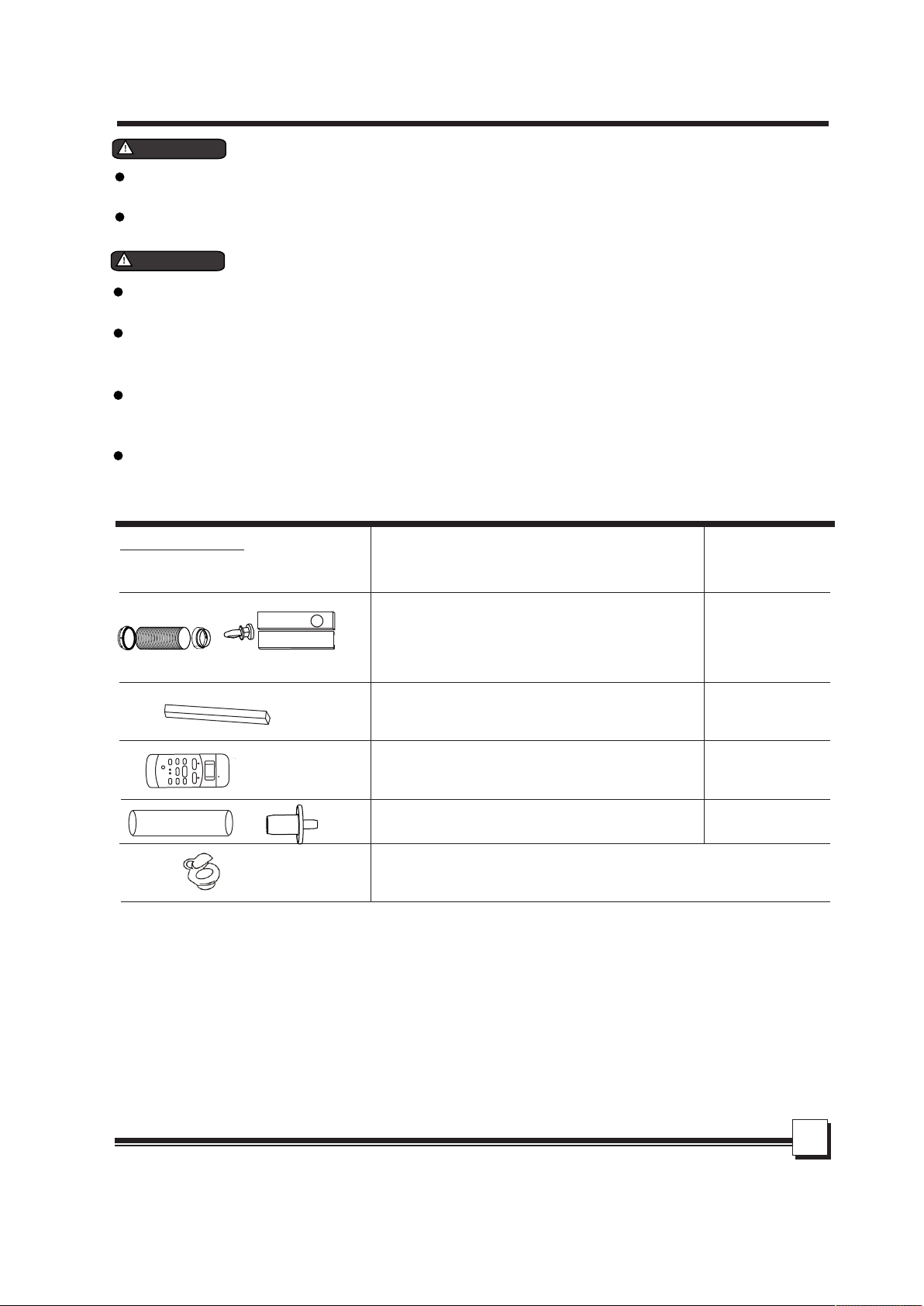
Accessories
PARTS :
PARTS NAME : QUANTITY :
Adaptor A (connects unit to hose)
Adaptor B (connects hose to slider kit)
1 set
Exhaust Hose
Window Slider Kit and bolt
Foam seal
ME
RESET LOCK
TEMP
ECONOMY
ON/OFF
LED
DISPLA
Y
TURBO
TURE( C)
FAN SPEED
TIMER OFF
TIMER ON
FAN
HIGH
MED
LOW
Remote Controller
(Requires 2 AAA batteries, not included)
AUTO
COOL
DRY
HEA
T
SET TEMPERA
MODE
SWING
ION
FOLLOW
Drain hose and drain hose adaptor
3/pcs
1pc
1pc
Wall adaptor for through-the-wall installation
(not included, option to purchase)
Please refer to page 12 for installation instructions
* Check to ensure all accessories are included in the package. Please refer to the installation instructions for
their usage.
NOTE:
All the illus trations in this manua l are for explanation pu rpose only. Your air conditioner
may be slight ly different. The actu al shape shall prevail .
4
Page 6

IDENTIFICATION OF PARTS
2
1
NAMES OF PARTS
Front
4
Control panel
1
Horizontal louver blade
2
(swings automatically)
Caster
3
Carrying handle
4
(both sides)
3
Fig.1
Rear
Upper air filter
5
6
7
8
9
15
14
13
5
(Behind the grille)
Upper air intake
6
7
Air outlet
Drain outlet
8
(Heating models only)
Power cord outlet
9
5
10
11
12
Fig.2
10
Power cord bracket
(for storage purposes only)
Bottom tray drain outlet
11
Power plug socket
12
(for storage purposes only)
Lower air filter
13
(Behind the grille)
Lower air intake
14
15
Drain outlet
Page 7
AIR CONDITIONER FEATURES
ELECTRONIC CONTROL OPERATING INSTRUCTIONS
Before you be gin, thoroughly fami liarize yourself wit h the functions of the con trol panel and
remote cont roller, then follow the s ymbol for the function s you desire.
The unit can be c ontrolled by the unit control panel alone or with the remot e controller .
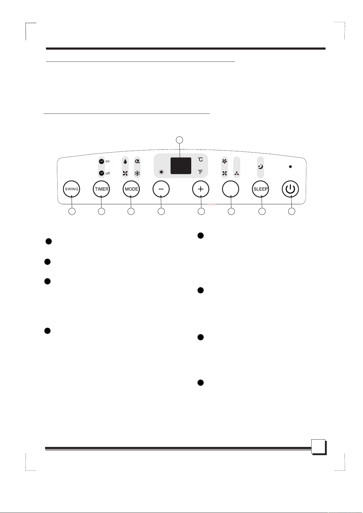
OPERATION PANEL OF THE AIR CONDITIONER
8
FAN
Fig.3
1
POWER button
Power switch, press to turn on/off.
2
SLEEP button
Used to initiate the SLEEP operation.
FAN button
3
Controls the fan speed. Press to select the fan
speed in four steps: LOW, MED, HI and AUTO.
The corresponding speed indicator light will illuminate,
except for AUTO speed. When AUTO speed is selected,
all fan indicators are dark.
4
UP( ) and DOWN( ) button
+
Used to increase or decrease temperature
setting in 1°C or 2°F increments.
Adjustable range: 62°F-88°F (17°C-30°C)
Also used to set timer between 0-24 hours
NOTE: The control is capable of displaying
temperature in Fahrenheit or Celsius. To
convert from one to the other, press and
hold the UP and DOWN buttons
simultaneously for 3 seconds.
-
2344567
MODE select button
5
Selects the appropriate operating mode.
Each press of the button will select mode
in the following sequence: AUTO, COOL,
DRY, FAN and HEAT(heating models only).
The corresponding mode indicator light
will illuminate.
6
TIMER button
Used to initiate the AUTO ON (start time) and
AUTO OFF (stop time) programs. Used in
conjunction with the + and - buttons. The
corresponding timer indicator light will illuminate.
SWING button
7
Used to initi ate the Auto swing feature. If
auto-swin g is in function, press th e button
again to stop t he louver at desired ang le.
LED Display
8
Displays se t temperature, in eith er °C or °F.
Displays au to-timer settings (i f any)
When unit is in D RY or FAN modes, displays
current roo m temperature.
1
6
Page 8

OPERATING INSTRUCTIONS
Error codes a nd protection code:
E1- Room temp erature sensor error -
Unplug the un it and plug it back in.
If error repe ats, call for service.
E2- Evapora tor temperature sens or error Unplug the un it and plug it back in.
If error repe ats, call for service.
E3- Condens er temperature senso r error Unplug the un it and plug it back in. If err or
repeats, ca ll for service.
E4- Display p anel communication e rror-
Unplug the un it and plug it back in.
If error repe ats, call for service.
P1- Bottom tr ay is full - Connect the dra in
hose to drain a nd empty the bottom tray.
If protection repeats, call for service.
Operating Instructions
COOL operation
- Press the MODE button until the "COOL"
indicator light comes on.
- Press the + or - buttons to set desired room
temperature. The temperature range is between
62°F-88°F (17°C-30°C).
- Press the FAN button to choose the
desired fan speed.
HEAT operation (heating models only)
- Press the MODE button until the "HEAT"
indicator light comes on.
- Press the + or - buttons to set desired room
temperature. The temperature range is between
62°F-88°F (17°C-30°C).
- Press the FAN button to choose the desired
fan speed.
DRY (dehumidify) operation
- Press the MODE button until the "DRY"
indicator light comes on.
- Under this mode, you cannot select a fan
speed or adjust the temperature. The fan
motor operates at LOW speed.
- Keep windows and doors closed for the
best dehumidifying effect.
- Do not connect exhaust hose fixture to window.
AUTO operation
- When you set the air conditioner in AUTO
mode, it will automatically select cooling,
heating (for heating models only), or
fan mode, depending on set temperature
and ambient room temperature.
- The air conditioner will operate in the
appropriate mode based on the set
temperature.
- Under AUTO mode, you can not
select the fan speed.
FAN operation
- Press the MODE button until the "FAN "
indicator light comes on.
- Press the FAN SPEED button to
select desired fan speed. The temperature
cannot be adjusted.
- Do not connect exhaust hose fixture to window.
TIMER operation
- When the unit i s on, pressing the
TIMER button will initiate the auto-stop
program, th e TIMER OFF indicator light
will illumi nate. Press the + or - butto ns to
set the time fo r unit to turn off.
Press the TIMER butto n again within 5
seconds wil l initiate the auto-st art
program, th e TIMER ON indicator light
will illumi nate. Press the + or - butto ns to
set the time fo r unit to turn on.
- When the unit i s off, pressing the
TIMER button will initiate the auto-start
program; pr ess again within 5 secon ds to
initiate au to-stop program.
- Press or hold t he +/- button to change ti me
in 0.5 hour inc rements, up to 10 hours;
then in 1 hour in crements, up to 24 hours .
The control panel will count down the
remaining t ime until program begi ns.
- The display will automaticall y revert
back to displ aying the previous
temperatu re setting if there is no ac tivity
within a 5 seco nd period.
- After timer ha s been programmed, if un it
is manually t urned ON or OFF; or if the
timer setti ng is adjusted to 0.0, any t imer
programme d will be cancelled.
- When unit mal functions and error co des
E1, E2, E3 or E4 is d isplayed, timer
programs wi ll also be cancelled.
7
Page 9

OPERATING INSTRUCTIONS
SLEEP operation
- If unit is running in COOL mode when SLEEP
function is activated, unit will automatically
increase set temperature by 1°C/2°F after 30
minutes. After another 30 minutes, unit will
again increase temperature by 1°C/2°F.
- If unit is running in HEAT mode (heating
models only) when SLEEP function is
activated, unit will automatically decrease set
temperature by 1°C/2°F after 30 minutes. After
another 30 minutes, unit will again decrease
temperature by 1°C/2°F.
- Unit will maintain the new temperature for 7
hours, then returns to original set temperature.
This ends the Sleep function and unit will
continue to operate as originally programmed.
Note: This feature is unavailable under FAN or
DRY mode
Swing automatical ly
Fig.4
Other features
Auto-Restart
If the unit bre aks off unexpectedly due to
power cut, it w ill restart at previou s function
when the powe r resumes.
Wait 3 minutes before resuming operation
After the uni t has stopped (or powere d off), there
will be a 3-min ute delay before unit wi ll start up
again. This is to protect the compressor. Operation
will automa tically resume after 3 m inutes.
Air flow direction adjustment
The louver ca n be adjusted automati cally (Fig. 4):
- When unit pow ers ON, the louver opens f ully.
- Press the SWI NG button on the panel or
remote cont roller to initiate the Au to swing
feature. The louver will automatically swing
up and down.
- Press SWING b utton again at desired a ngle
for set air flo w.
- Please do not a djust the louver manua lly.
8
Page 10

INSTALLATION INSTRUCTIONS
B
A: 12-40 inch es. B: 12 i nch es
Horizo ntal
window
Window S lide r Kit
Minimu m: 26. 57”
Maxmum : 48.4 3”
A
Fig.5
Fig.6
INSTALLATION INSTRUCTIONS
Location
The air conditioner should be placed on a firm
foundation to minimize noise and virbration. For
safe and secure positioning, place the unit on a
smooth, level floor strong enough to support the unit.
The unit has casters to aid placement, but it should
only be rolled on smooth, flat surfaces. Use caution
when rolling on carpet. Do not attempt to roll the
unit over objects.
The unit must be placed within reach of a properly
grounded socket.
Never place any obstacles around the air inlet or
outlet of the unit.
Allow 12 to 40 inches of space between the back
of the unit and the wall for efficient air-conditioning.
Window slider kit Installation
Your window slider kit has been designed to fit most
standard vertical and horizontal window applications.
However, it may be necessary for you to improvise or
modify some aspects of the installation procedures
for certain types of windows. Please refer to Fig. 6
and Fig.7 for minimum and maximum window
opening requirements.
Window slider kit can be fixed with a bolt (Fig.7a).
Horizo ntal
window
Win dow S lide r Kit
Minimu m: 26. 57”
Maxmum : 48.4 3”
bolt
Note: If the window opening is less than the
minimum required length and the slider kit needs to
be cut down to size, cut the piece with the hole in it,
but cut the end without the hole.
Do Not cut out the hole in the slider kit.
Fig.7
Slider kit length: 26.5 to 48 inches.
Window opening requirements:
Minimum = 26.57 inches
Maximum = 48.43 inches
Window s lide r kit
Fig.7a
9
Page 11

INSTALLATION INSTRUCTIONS
Installation for a double-hung sash window
Foam seal A
(adhesive type)
1. Trim foam seal (with adhesive) to the proper length and
attach to window stool (Fig.8)
2. Adjust the length of the slider kit according to the width
of the window. Place slider kit to window stool, on top of
foam seal (Fig.9)
Fig.8
3. Trim another foam seal (with adhesive) to the proper
length and place on top of the slider kit (Fig.10).
4. Close the window sash securely against the kit.
Window kit
5. Trim the last foam seal to the proper length to seal
C
the open gap between the top window sash and
outer window sash (Fig.11)
Window stool
Fig.9
Window kit
Foam seal
Window stool
Fig.10
Fig.11
10
Page 12

INSTALLATION INSTRUCTIONS
Installation for sliding sash window
Window
panel
Foam seal A
(adhesive type)
Fig.12
C
Fig.13
1. Trim foam seal (with adhesive) to the proper length
and attach to window frame (Fig.12).
2. Adjust the length of the slider kit according to the height
of the window. Place window slider kit against foam
seal (Fig.13).
3. Trim another foam seal (with adhesive) to the proper length
and attach it to the open side of slider kit (Fig.14).
4. Slide window close against the slider kit.
5. Trim the last foam seal to the proper length to seal the
open gap between the two window sashes (Fig.15).
Foam seal
Fig.14
Fig.15
NOTE: All illustrations in this manual are for explanation
purposes only. Your unit may differ slightly. The
actual shape shall prevail.
11
Page 13

Fig.16
Wall Adaptor
(sold separately, please contact
Sunpentown at 1-800-330-0388 or visit
www.sunpentown.com)
Screws & expansion plugs
(can be purchased at any hardware store)
INSTALLATION INSTRUCTIONS
Exhaust hose installation:
The exhaust hose and adaptor must be installed or removed
in accordance with the usage mode.
COOL, HEAT (heating models only)
or AUTO mode
Install
Opening
Hook
Expansion plug
position
Wall Adaptor
Cap
Fig.17
max 47 inches
FAN or DEHUMIDIFY mode
Remove
1. Attach both adaptors A and B to exhaust hose. Extend each
end of the hose by couple inches and turn the adaptors
as shown in Fig.16. Do not over-tighten. Refer to previous
pages for window kit installation.
2. Align the hooks on adaptor A to the openings of the air
outlet. Insert and slide downwards to install. (Fig. 17)
Through-the wall connection
NOTE: It is necessary to purchase the following parts for
through-the-wall installation:
min 12 inches
Fig.18
Fig.19
1. Prepare a hole in the wall and install the Wall Adaptor to the
opening (from outside). Secure with 4 expansion plugs and
screws. (Fig.18)
2. Attach exhaust hose to the Wall Adaptor.
Note: Cover the hole using the adaptor cap when not in use.
IMPORTANT:
DO NOT OVER BEND THE EXHAUST HOSE (SEE Fig.19)
The exhaust hose can be compressed or extended moderately
according to the installation requirement, but it is desirable to
keep the hose length to a minimum.
CAUTION:
Make sure there are no obstacles blocking the air outlet of
the exhaust hose (in the range of 20 inches), for the exhaust
system to work properly.
12
Page 14

INSTALLATION INSTRUCTIONS
Water drainage:
Continuous Drainage - COOL/DRY modes
Remove the upper drain plug from back of unit.
Attach drain connector (5/8” universal female
mender) to a 3/4” hose (not included, purchase
from any hardware store). Connect to spout.
Position the open end directly over drain area.
(Fig.20a)
Continuous Drainage - HEAT mode
(heating models only)
Remove the lower drain plug from back of the
unit.
Attach drain connector (5/8” universal female
mender) to a 3/4” hose (not included, purchase
from any hardware store). Connect to spout.
Position the open end directly over drain area.
(Fig.20b)
NOTE: Make sure connections are secure to prevent
leakage. Direct the hose downwards, as water
drainage is gravity-pulled, make sure there are no
kinks that may stop the water ow. Never direct the
hose upwards as in Fig. 21a and 21b.
Fig.22
Emptying the Water Tank
When the water in the bottom tray reaches its
maximum capacity, the unit will beep 8 times and
display will show “P1”. At this time, the
compressor will immediately stop (AC, Dry or
Heat) but fan will continue to operate.
Place a collection pan underneath the drain spout
or carefully move the unit to a drain location.
Remove the bottom drain plug and water will
begin to drain out. Fig.22
Replace the drain plug and restart unit. P1
indication should disappear.
Note: Be sure to replace the drain plug before
restarting the unit.
13
Page 15

CARE AND MAINTENANCE
CARE AND MAINTENANCE
1) Be sure to unplug the unit before cleaning or servicing.
2) Do not use gasoline, thinner or other chemicals to clean
the unit.
3) Do not wash the unit directly under a tap or spray with
water hose. It may cause electrical danger.
4) If the power cord is damaged, it should be repaired by
manufacture or its certified electrician.
1. Air filter
- Clean the air filter at least once every two weeks to prevent
inferior fan operation due to dust accumulation.
- Removal (This unit has two filters)
Upper Filter: Pull and remove according to arrow direction
in Fig. 23.
Lower Filter: First remove the screw as indicated in Fig.23,
remove filter.
- Cleaning
Wash the air filters by immersing gently in warm water
(about 40 C/104 F) with a neutral detergent. Rinse the filters
and allow to dry completely in a shady area - do not place
under direct sunlight.
- Mounting
Replace upper filter according to arrow direction in Fig.24
Replace lower filter and reinsert the screw. (Fig.24)
O O
2. Housing
- Use a lint-free cloth soaked with neutral detergent to clean
the unit’s housing. Finished by a dry clean cloth.
3. Storage
- Remove the rubber plug at the back of the unit and attach
a hose to drain outlet. Place the open end of the hose
directly over the drain area (See Fig.20 & 21).
- Drain water from the bottom tray by removing the plug from
the bottom drain outlet (See Fig.22).
- Turn unit on and run in FAN for half a day in a warm room.
This will dry the inside of the unit and prevent mold and
mildew growth.
- Power off the unit and unplug from power source. Wrap the
cord around the bracket and insert plug into the storage
socket. (Fig.25)
- Clean both filters and reinstall.
- Remove batteries from the remote and store with unit.
- Cover with a plastic bag and store in a cool, dry place.
14
Page 16

TROUBLESHOOTING TIPS
TROUBLE SHOOTING
TROUBLES
1. Unit will not start
2. Not cool enough
4. Noisy or vibration
5. Gurgling sound
POSSIBLE CAUSES
- P1 appears in the display window
- Room temperature is lower than
the set temperature.(Cooling mode)
- The windows or doors in the room
are not closed.
- There are heat sources inside the
room.
- Exhaust air duct is not connected or
blocked.
- Temperature setting is too high.
- Air filters are dirty.
- The ground is not level or not flat
enough.
- This is the sound of refrigerant
flowing inside the unit.
SUGGEST REMEDIES
Drain the water in the bottom tray.
Adjust the set temperature.
Make sure all the windows and
doors are closed.
Remove the heat sources if possible.
Connect the duct and make
sure it can function properly.
Decrease the set temperature.
Clean the air filters.
Place the unit on a flat, level
ground if possible.
This is normal.
6. Power shuts off in
Heat mode
(heating models only)
15
- Overheat protecti on. Whe n the
temperature at the ai r outle t
exceeds 70 C/15 8 F, the unit
will automaticall y shut off as a
protection featur e.
O O
Switch on again after the unit
has cooled down.
Page 17

Location of the remote controller.
26’
SET TEMPERATURE( C)
AUTO
COOL
DRY
HEA
T
F
AN
HIGH
MED
LOW
TEMP
MODE
ON/OFF
SWING
FAN SPEED
ECONOMY
ION
TIMER ON
RESET LOCK
FOLLOW
TIMER OFF
ME
LED
DISPLA
Y
TURBO
Replacing batteries
HANDLING THE REMOTE CONTROLLER
Use the remote controller within a distance of 26 feet
from the appliance, pointing it towards the receiver.
Reception is confirmed by a beep.
CAUTIONS
The air conditioner will not respond if curtains, doors or other barriers
block the signal from the remote controller to the unit.
Prevent any liquid from coming in contact with the remote controller.
Do not expose the remote controller to direct sunlight or heat.
If the infrared signal receiver on the unit is exposed to direct sunlight,
the air conditioner may not respond. Close curtains/blinds to block
sunlight from falling on the receiver.
If other electrical appliances react to the remote controller, move
those appliances if possible.
The remote controller is powered by two AAA batteries (not included).
The batteries are housed in the back of remote, protected by a cover.
(1) Remove the cover by pressing down and sliding off.
(2) Remove the old batteries and insert new batteries, placing the
(+) and (-) ends correctly.
(3) Replace cover by sliding it back into position.
NOTE: When the batteries are removed, any programming
will be erased. After inserting the new batteries, the remote controller
.
can be reprogrammed.
CAUTIONS
Do not mix old and new batteries or batteries of a different type.
Do not leave the batteries in the remote controller if it is not going to be used for extended period
of time (2 months or more).
Dispose old batteries at recycling centers - contact your local government for disposal practices
in your area.
Performance Feature
1. Operating Mode: AUTO, COOL, DRY, HEAT (Heating models only) and FAN.
2. Timer Setting Function in 24 hours.
3. Indoor Setting Temperature Range: 62°F to 88°F (17°C to 30°C)
4. Full function of LCD (Liquid Crystal Display)
(Operating temperature: -41°F to 140°F (-5°C to 60°C)
NOTE:
All illustrations i n this ma nual ar e for explanation purpose only. Your air c onditioner
may be differ slightl y. The actual shape sh all pre vail.
16
Page 18

HANDLING THE REMOTE CONTROLLER
Function buttons
AUTO
COOL
DRY
HEAT
1
3
4
5
1
TEMP DOWN Button
Push this button to decrease set temperature, in
increments of 2°F (1°C). Lowest is 62°F (17°C°)
TEMP UP Button
2
Push this button to increase set temperature, in
increments of 2°F (1°C). Highest 88°F (30°C°)
3
MODE Button
Each time the button is pressed, the operation
mode is selected in the following sequence:
AUTO
NOTE: Heat mode is for Cooling & Heating models only.
SWING Button
4
COOL
Press to start/stop auto swing feature. Or to set
desired angle for directional airflow.
5
RESET Button
If the recessed RESET button is pressed, all
current settings will be cancelled and the
controller will return to the default settings.
6
ON/OFF Button
Power button, press to turn unit ON/OFF.
7
FAN SPEED Button
Press to select the fan speed in four steps:
Auto Low Med High
DRY
HEAT FAN
SET TEMPERATURE( C)
TEMP
MODE
SWING
ON/OFF
ECONOMY
RESET LOCK
LED
DISPLAY
FAN SPEED
TIMER ON
TIMER OFF
10
11
12
FAN
HIGH
MED
LOW
2
6
7
8
9
10
11
12
8
TIMER ON Button
Press to activate Auto-on timer. Each press
increases the timer setting by 30-minutes, up
to 10 hours. Then at 1-hour increments, up
to 24 hours. To cancel the Auto-on timer, press
the button until time setting is 0.0.
9
ECONOMY(SLEEP) Button
Press to engage Sleep mode. Select this
function for the sleeping hours to maintain the
most comfortable temperature and save energy.
This function is only available under AUTO,
COOL and HEAT (heating models) modes.
NOTE: SLEEP function would be cancelled if
ON/OFF, FAN SPEED, SLEEP or MODE button
is pressed.
TIMRT OFF Button
Press to activate Auto-off timer. Each press
increases the timer setting by 30-minutes, up
to 10 hours. Then at 1-hour increments, up
to 24 hours. To cancel the Auto-off timer, press
the button until time setting is 0.0.
LOCK Button
Press this recessed button to lock all current
settings (a lock symbol will appear on the LCD).
When the remote is locked, it will not respond
to any actions except LOCK. Use the LOCK
mode when you want to prevent any accidental
setting changes. Press again to unlock
LED Display Button
Press this button to turn off the display on the
unit, press it again to light the display .
17
Page 19

Indicators on LCD
HANDLING THE REMOTE CONTROLLER
MODE display
Indicates the current selected mode: AUTO, COOL,
DRY or HEAT (heating models only).
Transmission Indicator
This transmission indicator lights up whenever remote controller
is transmitting signals to the AC unit.
Temp./Timer display
Displays the set temperature (62°F to 88°F / 17°C to 30°C) or
timer setting (0~24h).
If FAN mode is selected, there will be no display.
ON/OFF display
This indicator will be displayed when the unit is operating.
SET TEMPERATURE
TIMER ON OFF
MODE display (FAN mode)
FAN SPEED display
Indicates the selected fan speed: AUTO, HIGH, MED or LOW.
AUTO fan speed will have no indicator displayed.
When unit is operating in AUTO or DRY Mode, there will be no signals.
TIMER display
This display area indicates if Timer ON and/or Timer OFF has been set:
- TIMER ON: auto-on function is set
- TIMER OFF: auto-off function is set
- TIMER ON OFF: both auto-on and auto-off are set
LOCK Indicator
Indicates the remote is locked and will not respond to any changes
(except LOCK button).
18
Page 20

HANDLING THE REMOTE CONTROLLER
Using the remote controller
SET TEMPERATURE( C)
AUTO
COOL
DRY
HEAT
2
1
MODE
SWING
TEMP
ON/OFF
ECONOMY
RESET LOCK
LED
DISPLAY
FAN
HIGH
MED
LOW
FAN SPEED
TIMER ON
TIMER OFF
Auto operation
Ensure the unit is plug ged in an d power i s available.
1. Press the MODE butto n to sele ct Auto.
2. Press the TEMP up/do wn butt on to set d esired temperature,
between 62°F to 88°F (1 7°C to 30 °C). Ea ch press is in
3
increments of 2°F or 1° C.
3. Press the ON/OFFbu tton to s tart the air conditioner.
NOTE:
Under Auto mode, the unit will sense the difference between
ambient temperature and set temperature to determine the
operating mode: COOL, FAN or HEAT (heating models only).
Fan speed cannot be controlled in Auto mode. Unit automatically
selects the most appropriate speed.
If Auto mode is not comfortable for you, the desired mode can be
selected manually.
Cooling /Heating/Fan operation
SET TEMPERATURE( C)
AUTO
COOL
DRY
HEAT
TEMP
FAN
HIGH
MED
LOW
Ensure the unit is plug ged in an d power i s available.
1. Press the MODE butto n to sele ct COOL , HEAT (heat ing mod els
only) or FAN mode.
2. Press the TEMP up/do wn butt on to set d esired temperature,
between 62°F to 88°F (1 7°C to 30 °C). Ea ch press is in
2
1
MODE
SWING
ON/OFF
ECONOMY
RESET LOCK
LED
DISPLAY
FAN SPEED
TIMER ON
TIMER OFF
increments of 2°F or 1° C.
4
3. Press the FAN SPEED but ton to se lect fa n speed: Auto, Low,
3
Med or High.
4. Press the ON/OFF but ton to st art the AC unit.
NOTE:
In FAN mode, temperature setting is not applicable. There will be no
temperature displayed on the LCD. Only steps 1, 3 and 4 may be
performed.
19
SET TEMPERATURE( C)
AUTO
COOL
DRY
HEAT
2
1
MODE
SWING
TEMP
ON/OFF
ECONOMY
RESET LOCK
LED
DISPLAY
FAN
HIGH
MED
LOW
FAN SPEED
TIMER ON
TIMER OFF
Dry (Dehumidifying) operation
Ensure the unit is plug ged in an d power i s available.
1. Press the MODE butto n to sele ct DRY mode.
2. Press the TEMP up/do wn butt on to set d esired temperature,
between 62°F to 88°F (1 7°C to 30 °C). Ea ch press is in
3
increments of 2°F or 1° C.
3. Press the ON/OFF but ton to st art the AC unit.
NOTE:
In DRY mode, fan speed is au tomat icall y controlled.
Page 21

HANDLING THE REMOTE CONTROLLER
1
SET TEMPERATURE( C)
AUTO
COOL
DRY
HEAT
MODE
SWING
SET TEMPERATURE( C)
AUTO
COOL
DRY
HEAT
TEMP
ON/OFF
MODE
SWING
ECONOMY
RESET LOCK
TIMER ON
TEMP
ON/OFF
FAN SPEED
ECONOMY
RESET LOCK
LED
DISPLAY
FAN SPEED
TIMER ON
TIMER OFF
LED
DISPLAY
FAN
HIGH
MED
LOW
TIMER ON
TIMER OFF
FAN
HIGH
MED
LOW
Swing operation
Use the SWING button to adjust the Up/Down airflow direction.
1. When the button is quickly pressed once, the louver is adjusted by 6°.
Keep pressing the button to adjust louver to desired angle.
2. Press and hold for 2 seconds to activate/deactivate auto-swing function.
NOTE: When the louver swings to a position which would affect the cooling
(or heating) of the unit, it would automatically change the swing direction.
Timer operation
To set the Auto-on timer:
1. Press the TIMER ON button and remote will display TIMER ON. The last
auto-on setting and the signal “h” will also be displayed.
2. Press the TIMER ON button again to begin setting the desire time. Each
press of the button increases the time by 30-minutes, up to 10 hours.
Then by 1-hour increments, up to 24 hours.
To set the Auto-off timer:
1. Press the TIMER OFF button and remote will display TIMER OFF. The
last auto-off setting and the signal “h” will also be displayed.
2. Press the TIMER OFF button again to begin setting the desire time. Each
press of the button increases the time by 30-minutes, up to 10 hours.
Then by 1-hour increments, up to 24 hours.
After setting TIMER ON/OFF, there will be a one-half second delay before
the remote controller transmits the signal to the AC unit. The after another
1
2 seconds (approximately), the “h” signal will disappear and set temperature
2
will re-appear on the display window.
NOTE: Timer ON/OFF is limited to the following time settings: 0.5, 1.0, 1.5,
2.0, 2.5, 3.0, 3.5, 4.0, 4.5, 5.0, 5.5, 6.0, 6.5, 7.0, 7.5, 8.0, 8.5, 9.0, 9.5, 10,
11, 12, 13, 14, 15,16,17, 18, 19, 20, 21, 22, 23 and 24.
Set
h
TIMER ON
Off
Start
6 hours later
Examples of Timer setting
TIMER ON (auto-on operation)
The TIMER ON feature is useful when you want the unit to automatically
turn on, say before you return home from work.
Example:
To start the AC unit in 6 hours.
1. Press the TIMER ON button. Remote displays the last time setting and
the “h” signal.
2. Press the TIMER ON button repeatedly till “6:0h” is displayed on remote.
3. Wait for about 3 seconds and display will revert to show set temperature.
4. Auto-on function has been set.
20
Page 22

HANDLING THE REMOTE CONTROLLER
TIMER OFF (auto-off operation)
h
TIMER OFF
Stop
On
Set 10 hours later
h
TIMER ON OFF
2 hours later
after setting
Stop
10 hours later
after setting
On
Set
Start
The TIMER OFF feature is useful when you want the unit to automatically
turn off, say after you go to bed.
Example:
To have the AC unit turn off after 10 hours:
1. Press the TIMER OFF button. Remote displays the last time setting and
the “h” signal.
2. Press the TIMER OFF button repeatedly till “10h” is displayed on remote.
3. Wait for about 3 seconds and display will revert to show set temperature.
4. Auto-off function has been set.
COMBINED TIMER (auto-off / auto-on)
This feature is useful when you want the unit to stop after you leave the
house and to start again upon your return.
Example:
To stop the AC unit in 2 hours and start up again in 10 hours.
1. Press the TIMER OFF button to initiate auto-off programming.
2. Press the TIMER OFF button repeatedly till “2.0h” is displayed.
3. Press the TIMER ON button to initiate auto-on programming.
4. Press the TIMER ON button repeatedly till “10h” is displayed.
5. Wait for about 3 seconds for display to revert back to set temperature.
Off
Set
SET TEMPERATURE( C)
AUTO
COOL
DRY
HEAT
MODE
SWING
TIMER ON OFF
Start
2 hours later
after setting
TEMP
ON/OFF
ECONOMY
RESET LOCK
LED
DISPLAY
h
5 hours later
after setting
FAN
HIGH
MED
LOW
FAN SPEED
TIMER ON
TIMER OFF
Stop
COMBINED TIMER (auto-on / auto-off)
This feature is useful when you want the unit to start before you wake up
and stop after you leave the house
Example:
To start the AC unit in 2 hours and stop after 5 hours.
1. Press the TIMER ON button to initiate auto-on programming.
2. Press the TIMER ON button repeatedly till “2.0h” is displayed.
3. Press the TIMER OFF button to initiate auto-off programming.
4. Press the TIMER OFF button repeatedly till “5.0h” is displayed.
5. Wait for about 3 seconds for display to revert back to set temperature.
ECONOMY(SLEEP) operation
Press ECONOMY button to engage the economic (sleep) operation.
The set temperature will increase (cooling) or decrease (heating) by 1°C/2°F
after 30 minutes and by another 1°C/2°F after an additional 30 minutes. The
new temperature will be maintained for 7 hours before unit returns to
originally set temperature.
NOTE: The ECONOMY (sleep) function is only available under COOL,
HEAT (heating models only) and AUTO mode.
1
21
Page 23

Your Guarantee
If this product is found to be faulty as a result of faulty materials or workmanship within one
year from date of purchase, it will be repaired free of charge.
This guarantee is subject to the following terms:
Sunpentown must be notied of the fault.
Proof of purchase must be presented to Sunpentown's nominated representative.
The warranty will be void if the product if modied, misused or repaired by an
unauthorized person.
The warranty after repair will not be extended beyond the original one-year period.
All replacement parts will be new or reconditioned.
Parts, which are replaced, become the property of Sunpentown.
The warranty applies for the use of the product in the USA only.
What is NOT COVERED:
Warranty does not include freight charges.
Incidental or consequential damage caused by possible defects with this product.
Damage to product caused by improper power supply voltage, accident, re, oods or
acts of nature.
Failure of product resulting from unauthorized modications to the product.
Improper installation or failure to perform the necessary maintenance.
This GUARANTEE is in addition to your Statutory Rights
SUNPENTOWN INTERNATIONAL INC.
14625 Clark Ave. City of Industry, CA 91745
Tel: 800-330-0388
service@sunpentown.com
www.sunpentown.com
 Loading...