

Page 1
OWNER’S MANUAL
16” Stand Fan
Model: SF-16D31
Version 1.0 2015
READ AND SAVE THESE INSTRUCTIONS
Attention: Pictures in the IM are for reference only.
Page 2

CAUTION
Read Rules for Safe Operation and Instructions Carefully.
WARNING
1. This appliance has a polarized plug (one blade is wider than the other). To reduce
the risk of electric shock, this plug is intended to fit in a polarized outlet only one
way. If plug does not fit fully in the outlet, reverse the plug. If it still does not fit,
contact a qualified electrician. Do not attempt to defeat this safely feature.
2. To reduce the risk of fire or electric shock, do not use this fan with any solid state
speed control device.
RULES FOR SAFE OPERATION
1. Never insert fingers, pencils, or any other object through the grille when fan is
running.
2. Disconnect fan when moving from one location to another.
3. Disconnect fan when removing grilles for cleaning.
4. Be sure fan is on a stable surface when operating to avoid overturning.
5. Do not use fan in window. Rain may create electrical hazard.
6. Ensure that the fan is switched off from the supply mains before removing the grille.
The rules about cord and plug as below:
1. This product employs overload protection (fuse). A blown fuse indicates an
overload or short-circuit situation. If the fuse blows, unplug the product from the
outlet. Replace the fuse as per the user servicing instructions (follow product
marking for proper fuse rating) and check the products. If the replacement fuse
blows, a short-circuit may be present and the product should be discarded or
returned to an authorized
service facility for
examination and/or repair.
2. Do not operate any fan with
a damaged cord or plug.
Discard fan or return to an
authorized service facility
for examination and/or
repair.
3. Do not run cord under
carpeting. Do not cover
cord with throw rugs,
runners, or similar coverings.
Do not route cord under
furniture or appliances.
Arrange cord away from
traffic area and where it will
not be tripped over.
Front Guard
Center Piece
Circlip
Clip
Tighten
Spinner
Blade
Plastic Nut
Loosen
Rear Guard
Control Part
Remote
Control
Hook
Base
Shaft
Motor
Power Cord
Screw
Female Terminals
Pole
PART FIGURE
Knob
Note: All the pictures in this manual are for explanation purpose only. Any discrepancy between
the real object and the illustration in the drawing shall be subject to the real subject.
1
Page 3
ASSEMBLY INSTRUCTION
1. Take out the base tube, three butterfly screws for fixed base and the round base
from the packing carton;
2. Insert the tube to the round base, be sure to make the positioning screw align with
the base;
3. Screw the three butterfly screws into the holes on the tube and tighten them;
4. Loosen the fastening knob, adjust the height of inner tube and tighten the knob.
5. Take out the control part of the fan from the packing carton, loosen the fastening
screw at the back of the box, insert the inner tube into the bottom hole, make sure
that the fastening screw and the fastening knob in the same position.
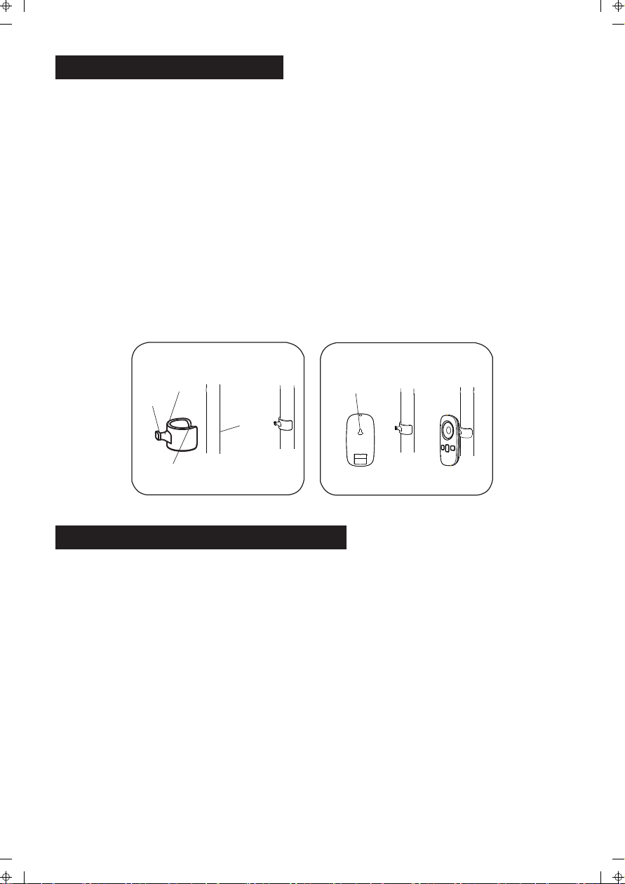
6. Usage of the remote control hook: make the straight face of hook up, clip the hook
to the inner tube along with the opening, the hook can be moved up and down
along the tube (Fig.1). The hook of the remote control may be linked to the
hole for storage when not in use. (Fig.2)
Fig. 1 Fig. 2
Straight face
Hook
Inner tube
Opening
Hook hole
GUARD & FAN BLADE ASSEMBLY
1. Unscrew and remove the spinner clockwise (or obtain from parts bag), and the
plastic nut counterclockwise. You may have to hold the shaft in place with one
hand to unscrew the spinner with the other. Position the rear guard against the
motor face so that the two pins on the motor face fit through the matching holes
in the rear guard. Tighten the rear guard into place with the plastic nut. (Fig.3)
2. Mount the blade set onto the motor shaft through the center hole in the blade
set. Insert the pin on the motor shaft into the notches on the back of the blade
set. Turn the spinner counterclockwise onto the shaft to tighten the blade set
into place. (Fig.4)
3. Remove the small screw from the clear plastic clasp on the bottom of the front
guard and set aside. Place the front guard over the rear guard so that the tab
at the top of the front guard fits over the rear guard rim (Fig. 5). Push the two
guards together. Close the clasp at the front guard bottom over the rear guard
rim, and re-insert and tighten the small screw removed earlier.
2
Page 4

Fig.3
Fig.4
Blade Set
Fig.5
On/Off
Drive plate
OSC
Fig.6 Fig.7
PRO/Timer
Mode
Remote controller
Battery
Battery cover
OPERATING INSTRUCTIONS
Plug in the power adapter, after a "beep" tone, the fan is on standby.
I. Remote Controller (Fig.6)
“ ” ON/OFF KEY
The standby mode, press this button, the fan to memory stall start. In the operation
of the fan, press this button, the fan off to standby state.
“ ” DRIVE PLATE
After start, rotate the drive plate clockwise, the fan increases from the current level
circulation in the following manner: normal wind 01 → normal wind 02 → ......→
normal wind 12, rotate the drive plate counterclockwise, the fan will decrease from
the current level in the following manner: normal wind 12 → normal wind 11 → ......
→ normal wind 01
“ ” MODE KEY
Repeat press this button, the wind will be switched in order of “normal wind - natural
wind - sleep wind - mute - normal wind - ... ".
Normal wind: The wind speed is constant set by the wind level, when the "normal
wind" icon is lit, 01 - 12 levels are normal wind;
Natural wind: Fan will simulate natural wind according to pre-programmed manner,
the wind speed changes in accordance with the program, which makes people
feeling idle, naturally and it likes to be in the nature.
Smart wind:
The wind weakens step by step during the preset time until stop. And then the fan
switches automatically off so that man can drop asleep.
Mute: Press this key to make the fan switch to the mute mode, in which the noise is
low and the mute indicator “ ”will be on. Press this key again, the fan will switch to the
normal air mode and work at the low speed.
3
Page 5

“ ” OSC KEY
After the fan starts, repeatedly touch this button to start or stop oscillation.
“ ” PRO KEY
Under power-on state, timed power-off can be set. Press the PRO button; it starts the
timing power-off state. "Timing" and icon displayed on the fan display will flash once
per second, the rotate the drive plate clockwise, the fan display will display 0.5 → 1.0
→ ...... → 7.5 → 00 → 0.5 → ...... in cycle, rotate the drive plate counter-
clockwise, it cycles as 7.5 → ...... → 0.5 → 0 0 → 7.5 → .......
When set a time, 5 seconds without any operation, the timing on the display flashes
twice and beep to refer successfully settings, if there is any button operation in five
seconds (except for on/off button), the time is successfully set and the fan returns to
current state immediately, "Timing" and icon stops flashing, if the timing button is
pressed in five seconds then timing is cancelled. If there is time setting, then “Timing"
and icon is lit, if not, it is off. When setup is successful, the display returns to display
the wind level.
Under standby mode, press the PRO button to set power-on time, "PRO" and icon is
lit, the operation mode please refers to timed power-off; rotate the drive plate to
adjust the time. After adjustment, the set time will be displayed on the screen. To
cancel a time setting, user only need to repeatedly press the PRO button.
Inquiry: Under working state, press forward/timing button to enter the timing status,
user can check the set time, and user can re-set the time in five seconds; if no
operation within five seconds, the time shown on the screen flashes twice and
returned to the wind level.
II. Control Panel (Fig.8)
• On/Off button
Same as them on remote control.
• Function button
1. Under working state, short press the function
button, the fan will alternate between oscillation
and fix; Long press the button, the fan enters
into the timing function, refer to the operating
instructions of PRO button on remote control
(To cancel the timer, long press function button).
2. Under standby mode, short press of the function
button is invalid; Long press the function button,
the fan enters into the appointment starting
function, refer to the operating instructions of
PRO button on remote control (To cancel the
timer, long press function button).
III. Tilt Adjustment
To adjust the air flow upward or downward, push
the guards lightly to the desired direction.
4
Fig.8
Function buttonOn/Off button
Page 6

IV. Height Adjustment
Lowing: lift up the head with a hand, unscrew the fastening knob counterclockwise
with the other hand, slowly lower the head to an appropriate height, and tighten the
knob clockwise. Rising: lift up the head with a hand, unscrew the fastening knob
counterclockwise slowly with the other hand, rises up the head to a proper height,
and tighten the knob clockwise.
V. Pivoting Angle Adjustment
When adjust the pivoting angle, fix the guards with hands and reverse the head of fan.
Note: Do not forcibly twist the fan in order to avoid damage to the fan.
VI. Screen-off Function
Press the “On/Off" button for three seconds, the screen will turn off and the fan is still
running. Press any button [not include "On/Off” button), the screen will light up.
Remote control does not have this feature.
VII. Forced Shutdown
The fan will be turned off when there is no operation within 12 hours.
BATTERIES INSTRUCTIONS (Fig.7)
Batteries should be installed before using the remote control. It uses a 3 -volt button
battery.
(1) Open the battery cover;
(2) install a new battery, pay attention to the battery polarity (+ and -);
(3) Close the battery cover.
HOW TO USE THE REMOTE CONTROLLER CORRECTLY
1. The remoter controller must point to the receiving window of the fan box when it
is used;
2. The remoter controller can be normally used within five meters and 30 degrees
from the fan;
3. Avoid direct sunlight on the receiving window, so as not to affect the receiver's
effect;
4. Remove the built-in batteries when do not use the remote control for a long time
or before the batteries are leaked.
OVERHEAT PROTECTION OF THE MOTOR
The windings of the motor have a thermal-fuse that burns out and the fan switches
off and temperature of the motor is no longer going up so that plastic parts of the fan
don’t subject to deformation so far so to be burned by the overheat if the motor is
overheat for any unexpected reason.
5
Page 7

USER SERVICING INSTRUCTIONS
a) Grasp plug and remove from the receptacle or
other outlet device. Do not unplug by pulling
on cord.
b) Open fuse cover. Slide open fuse access
cover on top of attachment plug towards blades.
c) Remove fuse carefully. Insert the tip of your tool
into fuse slot (close with the terminal), then prize
the fuse gradually and slowly, but not overexert. If you feel tight, you can try it at
several times and prize the fuse little by little. When one side of the fuse has
been prized, then you can get the fuse out entirely.
d) Risk of fire. Replace fuse only with 2.5 Amp, 125 Volt fuse.
e) Close fuse cover. Slide closed the fuse access cover on top of attachment plug.
f) Risk of fire. Do not replace attachment plug. Contains a safety device (fuse) that
should not be removed. Discard product if the attachment plug is damaged.
Notice:
1. When you replace the fuse, please don’t operate suddenly or overexert, or else
the product will be damage or cause accident.
2. When you feel it hard to be operated, please make sure you have got the right
way.
CLEANING
1. Be sure to unplug from the electrical supply source before cleaning.
2. Plastic parts should be cleaned with mild soap and a damp cloth or sponge.
Thoroughly to remove soap film with clean water.
3. Be sure not to make water or other liquid enter inside of motor.
6
Page 8

Your Guarantee
If this product is found to be faulty as a result of faulty materials or workmanship within
s
one year from date of purchase, it will be repaired free of charge.
This guarantee is subject to the following terms:
●
Sunpentown must be noti�ed of the fault.
●
Proof of purchase must be presented to Sunpentown's nominated
representative.
The warranty will be void if the product is modi�ed, misused or repaired by an
●
unauthorized person.
●
The warranty after repair will not be extended beyond the original one-year
period.
●
All replacement parts will be new or reconditioned.
●
Parts, which are replaced, become the property of Sunpentown.
●
The warranty applies for the use of the product in the USA only.
What is NOT COVERED:
●
Warranty does not include freight charges.
●
Damage due to installation error, product abuse and/or misuse.
●
Incidental or consequential damage caused by possible defects with this
product.
●
Labor cost incurred for the installation and/or removal of a possible defective
unit.
●
Damage to product caused by improper power supply voltage, accident, �re,
�oods or acts of nature.
●
Failure of product resulting from unauthorized modi�cations to the product.
●
Improper installation or failure to perform the necessary maintenance.
●
Normal wear and tear on parts or replacement of parts designed to be
replaced.
●
Damage to personal property from use of product.
●
Replacement or repair of household fuses, circuit breakers, wiring or plumbing.
This GUARANTEE is in addition to your Statutory Rights
SUNPENTOWN INTERNATIONAL INC.
14625 Clark Ave. City of Industry, CA 91745
Tel: 800-330-0388
service@sunpentown.com
www.sunpentown.com
7
 Loading...