

Page 1

18inch Built-In Dishwasher
Install ation Instruct ion
SD-9252W
SD-9252SS
Page 2

READ CAREFULLY AND KEEP THESE INSTRUCTIONS.
BEFORE INSTALLATION
Read these instru ctions com pletely an d carefully.
IMPORTANT
Observe all gover ning codes a nd ordinan ces.
Note to Installer
Be sure to lea ve these ins truction s for the con sumers
and local inspect ors use.
Note to Consumer
Keep th ese instru ctions wit h your Owners Man ual for
future reference .
Skill level
Installation of this dishwashers require basic mechanical
and ele ctrical sk ills. Imprope r ins tallatio n can result in
product fa ilure which is no t covered under the Product
Warranty.
CONTENTS
Mater ial You Will Need
Tools
Unit Dimensions
Prepare the Locat ion
Corner Installa tion
Ways of Drain Connections
Prepare Electri cal Wiring
Elect rical Requ irement
Prepare Water Line
Adjust Door Balan ce
Remov e Toekick
Insta ll Power Cor d
Position Water Line and House Wiring
. . . . . . . . . . . . .. . . . . .. . . . . . . . . . . . . . . . . . . . . . . . . . . 1
. . . . . . . . . . . . . . . . . . . . . . . . . . . . . 1
. . . . . . . .. . . . . . . . . . . . . . . . . . . . . . . . . . . 2
. . . .. . . . . . . . . . . . . . . . . . . . . . . . . . . 2
. . .. . . .. . . . . . . . . . . . . . . . . . . . . . . . . . . 2
. . . .. . . .. . . . . . . . . . . . . . . . . . . 2
. .. . . .. . . .. . . . . . . . . . . . . . . . . . . 3
. . . . . . . . . . . . . . . . . . . . . . . . . . . . . . 3
. . . .. . . . . . . . .. . . . . . . . . . . . . . . . . . . . 4
. . . .. . . . . . . . . .. . . . . . . . . . . . . . . . . . . 4
. . . .. . . .. . . . . . . . . . . . . . . . . . . . . . . . . . . . 4
. . . .. . . .. . . . . . . . . . . . . . . . . . . . . . . . . 5
. . . . . . . . . . . . . . . . 5
IMPORTANT
The dis hwasher mu st be instal led to allow f or future
remov al from the en closure if s ervice is required.
Before You Begin--Examine the dishwasher carefully,
if the produ ct is damage d, you shoul d immediat ely contac t
your deale r.
FOR YOUR SAFETY
Read ca ref ully all WARNINGS and CAUTIONS in this
instructions which will gua rantee you r saf ety.
Inser t Drain Hose through Cab inet
and Con nect Water Line
Slide D ishwasher into Cabin et
Level D ishwashe r
Position Dishwasher, Secure to Cabinet
Connect Water Supply
Connect Drain Lin e
Pre-Test Check List
Dishwasher Wet Test
Repla ce Toekick
Liter ature
. . . . . . . . . . . . . . . . . . . . . . . . . . . . . . . . . . 6
. . . .. . . .. . . . . . . . . . . . . . . . . . . . . . . . . . . 9
. . . .. . . .. . . . . . . . . . . . . . . . . . . . . . . . . . . . . . . . 9
. . . .. . . .. . . . . . . . . . . . . . . . . . . 5
. . . .. . . . . . . . . . . . . . . . . . . 6
. . . .. . . . . .. . . . . . . . . . . . . . . . . . . 7
. . . . . . . . . . . . .. . . . . . . . . . . . . . . . . . . 8
. . . .. . . . . . . . . . . . . . . . . . . . . . . . . . . . 9
. . . .. . . .. . . . . . . . . . . . . . . . . . . . . . 9
. . . . . . . . . . . . . 7
Page 3

Installation Preparation
1
Page 4
choos e C and D.
Installation Preparation
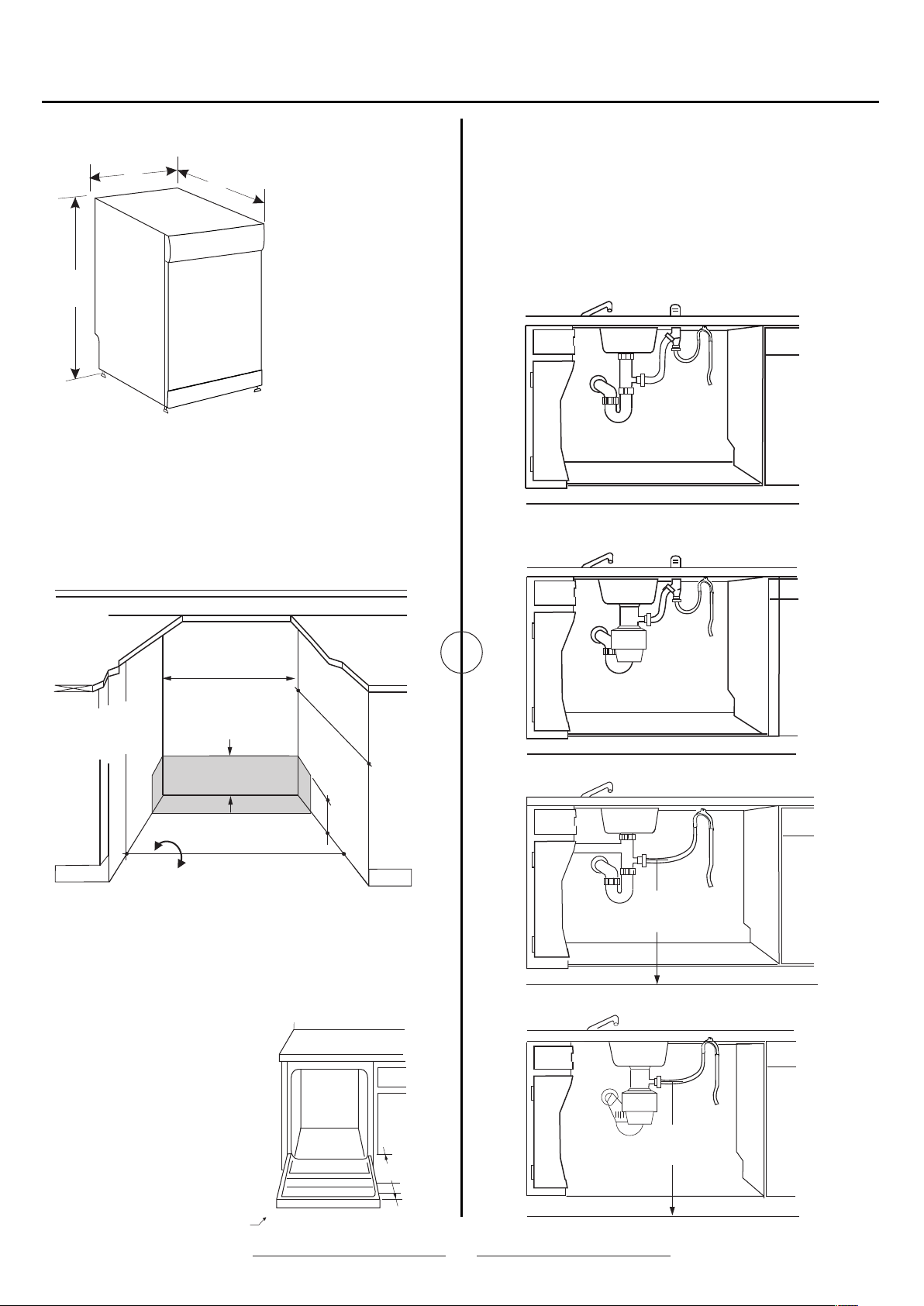
UNIT DIMENSIONS
18"
33 ~35" "
Figure 1
23"
DEPTH£ 23"(580mm)
WIDTH£18"(450mm)
HEIGHT £33"~35"
(840~890m m)
PREPARE THE LOCATION
The dis hwasher shoul d be install ed near a sink for
water supply connection and proper drainage.
A build- in dishwas her must be f ully enclo sed on
the top, sides and back, and must not support any
part of the enclosu re.
DRAIN CONNECTIONS
The type of drain installation depends on the answers to
the following questions:
• Is air gap required by local codes and ordinances?
• Will waste tee or disposer connection be less than 18”
above the floor?
If both answers are YES, use method A or B. Otherwise
choose C or D.
A) air gap wit h waste tee
Figure 4
B) air gap wit h disposer
Are a of Pi pe or wi res
Min. 24 "
33 35-1/2" "
Underside of
Counterto p to Floo r
Are a of Pl umbing an d
Electr ic Se rvice
6"
Min. 18 "
Floor mu st be Even
Wit h Roo m Floor
Figure 2
DEPTH£ 24"(610mm)
WIDTH£18" (460mm)
HEIGHT £33"~35-1/ 2"(840~900 mm)
CORNER INSTALLATION
When in stalled in to a corner,
allow 2 ” minimum cl earance
between dishwasher and
adjacent cabinet, wall or
other appl iances. Allow 22"
clear ance from the front
of the dishwasher for door
opening.
Figur e 5
C) waste tee
18"
Min.
Figur e 6
D) disposer
18"
Min.
22"
Minimum Clearance 2"
Figur e 3
Figur e 7
2
Page 5

Installation Preparation
PREPARE ELECTRICAL WIRING
WARNING!
FOR PER SONAL SAFET Y:
Remove house fuse or ope n circuit breaker before beginning installation. Do not use an extension cord or adapter
plug with this appliance.
GROUNDING INSTRUCTIONS--Power Cord Models
This appliance must be grounded. I n the event of a m alfunction or breakdown, grounding will re duce the ris k of
elect ric shock by p rov iding a path o f least resista nce for electric current. This appliance is equipped with a cord
having an equipment-groundin g conductor and a g rou nding plug . The p lug must be pl ugged into a n appropriate
outlet that is installed in an accordance w ith all loca l codes and or dinances .
WARNING!
Improper conn ection of th e equipmen t-grounding c onductor can result in a risk of electric shock .Check with a qualified
elect rician or servi ce representative if you are in doubt wether the appliance is properly grounded. Do you modify the plug
provided w ith the appl iance; If it w ill not fit th e outlet, ha ve a proper outlet installed by a qualified electrician.
GROUNDING INSTRUCTIONS--Cable Direct
This appliance must be connected to a grounded m etal, perm anent wiri ng system ,o r an eq uipment- gro unding
conductor must be run wi th the circuit co nductors a nd connect ed to the equi pment-groun ding termi nal or lead on
appliance.
ELECTRICAL REQUIREMENT
This dishwasher is designed for operation on an adequately wired individual 120VAC, 60HZ, and connected to an
indiv idual, proper ly grounded bra nch circuit, protected by a 15 or 20 amp circuit breaker or time-delay fuse.
If the electric supply does not meet the above specifi cations, contact a licensed electric ian before proce eding.
Your dishwasher circuit should not be used for any other appliance while the dishwasher is in operat ion. The
dishwasher requires the f ull capac ity of the circuit.
If the wall socket used for th e dishwas her is controlle d by a swit ch, turn o ff the swi tch before in stallati on.
1
The pow er-sup ply socket f or the appliance shall be
insta lled in a cabi net or on a wall adja cent to the
undercou nter space in whi ch the appli ance is to be
insta lled.
There shall be an opening through the partition
2
between the compartments specified in 1 that is
large enough for the attachment plug to pass through.
The longest dimension of the opening shall not be
more than 38mm.
The edges of the opening specified in 2 shall, if the
3
partition is wood, be smooth and rounded, or, if the
partition is metal, be covered with an edge protector
provided for this purpose by the manufacturer; and
Care shall b e exercised, wh en the appli ance is
4
installed or re moved, to reduc e the likeli hood of
damage to the power-suppl y cord.
10"
6"
10"
Receptacle
Location
Area
6"
Alternate
Receptacle
Location
1-1/2" Dia. Hole (Max.)
24"
from Wall
Ground
Black
Figur e 8
3"
from
Cabinet
White
ELECTRICAL CONNECTION
Elect rical conn ection is on t he right front of d ishwashe r.
For cable di rec t connecti ons the cabl e must be routed as s hown. Cabl e must exten d a minimum of 2 4” from the rear
wall. F or po wer cord co nnection s, install a 3-prong grounding t ype receptacl e in the sink ca binet rear wall, 6” min.
and 16”max. From the ope ning, 6”to 16” above the floor.
3
Page 6

Installation Instructions
PREPARE WATER LINE
The lin e may enter from eithe r sid e, rear or floor within
the shaded area.
The lin e may pass throug h the same hol e as the elect rical
cable a nd drain hose. Or cut an additional hole of 1-1/2”
max.
Note: Power cords with p lug must pas s through a
separate hole.
4"
2" From Floor
5"
4"
6"
Shut-off
Valve
Hot
2"
From
Cabinet
Cabinet Face
1-1/2" Dia.
Hole
Figur e 9
5"
19" From Wall
ADJUST DOOR BALANCE
To check door balance, hold the top of the dishwasher
firmly. Open the door slowly, if the door drops when
released, increase spring tension. If the door closes
when released, decrease tension.
Increa se
Spring
Tension
Decrea se
Spring
Tension
Figur e 10
WATER LINE CONNECTION
Note to Consumer
This dishwasher can use both hot or cold water.
* Turn off the water supply.
* Install a hand shut-off valve in an accessible
locat ion, such as under the sink. (O ptional bu t
strongly reco mmended. )
* Water connection is on the left side of the dishwasher.
Install the hot water in let line, us ing no less th an 3/8¡
O.D. Copper tubing. Ro ute the line a s shown and extend
forward at least 19” fro m rea r wal l.
* Flush w ater line to clea n out debris .
* The water pressure must be 20-120 PSI .
REMOVE TOEKICK
Remov e the two screws to remo ve toekick .
ADJUSTMENT
If door does not open easily or falls too quickly, you
should adjust the tension of door spring:
Pull th e spring adjustment pin out of the holes, insert
it in the next highes t or lo west hole an d test again .
Continue moving the spring pin until door is balanced.
Figur e 11
4
Page 7

Installation Instructions
INSTALL POWER CORD
Skip this step if dishwasher will be d ire ct wired or has
a facto ry install ed power cord.
The power co rd and conne ctions mus t comply wit h
the National Elec trical Cod e, Section 4 22 and/or
local c odes and ord inances.
Be sure powe r is tu rned off at th e source.
1. Remove junction box cover.
2. Secu re ho use wiring t o the back of th e junction
box with a strain relief .
3. Connect incoming power cord whi te (or ribbed) to
dishwasher white, bl ack (or smooth) t o black and
Ground to green w ire . Use UL listed wire nuts of
appropri ate size.
4. Replace juncti on box cover. Check to be sure
that wires a re no t pinched un der the cov er.
A
Remove
Juncti on Box
Cover
B
Check That Whi te, Black a nd
Gre en Dishwashe r Wir es Are Threaded
Thru Sma ll Hole in Br acket
C
Insert P ower
Cord Wire s Thru
Strain R elief
and Tig hten
Gro und
Figure 12
White
Black
D
Use UL List ed
Wir e Nuts
WARNING!
If house wiring is not 2-wire with ground, a ground must
be pro vided by t he instal ler . When hou se wiring is
alumi num, be su re to use U L Listed anti-oxidant
compo und and al uminum -t o-copper Connecto rs
POSITION WATER LINE
AND HOUSE WIRING
Posit ion water suppl y line and hou se wiring on t he
floor ofth e opening to a void inter ference with ba se of
dishwasher and compo nents under dis hwasher.
6"
4"
5"
4"
5"
4"
6"
INSERT DRAIN HOSE AND
CONNECT WATER LINE
Upright the dishwasher and posit ion in the front of
opening. Insert drain hose into cabinet wall hole.
If a power cor d is used, gui de the end throug h a
separate hole.
Water
Line
House
Wir ing
Figure 13
Figure 14
Connect the water line of dishwasher into user wat er li ne.
5
Page 8

Installation Instructions
SLIDE DISHWASHER INTO CABINET
DO NOT PUSH AGAINST FRONT PANEL WITH KNEES.
DAMAGE WILL OCCUR.
Slide d ishwasher int o the openin g a few inches a t a time.
As you proceed, pull the drain hose through the opening
under the sink. Stop pushing when the dishwasher is a
few inches forward of adjacent cabinetry.
Make sure drain hose is not kinked under the dishwasher
and there is no interference with the water line and
wiring or any other component.
Figur e 15
LEVEL DISHWASHER
IMPORTANT– Dishwasher must be level for proper dish
rack op eration an d wash performance.
* Place l evel on door and ra ck track ins ide the tub as
shown to check that the dishwasher is level.
* Level t he dishwasher by adjusting the four leveling legs.
* If adjustment to the right rear levelin g leg is required,
loose n junction b ox bracket scre w and rotate brac ket
clock wise.
Turn Legs
to Adjust
Figur e 16
Check
Level
Front
to Back
Check Level
Side To Side
Figur e 17
6
Page 9

Installation Instructions
POSITION DISHWASHER, SECURE TO CABINET
The dis hwasher must be s ecured to the cou ntertop or
the cab inet sides . Whe n countert ops are made of woo d
use Met hod 1. When count ertops are gran ite or other
mater ials that wi ll not accep t screws, use Met hod 2 to
secure at th e sides.
Metho d 1: Secure dishw asher to wood cou ntertop
Posit ion dishwasher so that the do or li nes up with th e
front face o f adjacent c abinets.
Fasten the dishwasher to the under side of the co untertop
with the 2 Phillips s pecial hea d screws provided.
Metho d 2: Secure dishw asher with side -mountin g brackets
Posit ion dishwasher so that the do or li nes up with th e
front face o f adjacent c abinets.
Remove plug buttons (one on each side)
Install screws through th e dishwash er si de mount bra cket
and into the adjacent cabinet on each side. Reinstall plug
buttons.
Bracke ts
Bracke ts
Figure 18
Wood C ountertop
3/4"
Figur e 19
When step is complete (either meth od), close d ishwashe r
door and ver ify that gap b etween cou ntertop an d top of
dishwasher door is at least 1 /2”.
IMPORTANT:
Figur e 20
Check to be sure the dishw asher is centered in t he
opening and there is no in terference wi th adjacen t
cabin ets when opening or closing t he door
Drive s cre ws straigh t and flush. P rot ruding screw he ads
will sc ratch the to p or si des of the con tro l panel and ca n
inter fere with door closi ng.
CONNECT WATER SUPPLY
IMPORTANT– Check to be sure that dishwash er does no t rub o r
contact th e fill hose or wa ter supply line. Test by openin g and
closing th e door. Re-route the lines if a rubbing n ois e or
interference occurs .
* Wra p 90º elbow with tread seal tape.
* Wra p 90º elbow onto the water valve.
* Do not over tighten th e 90º e lbow, water va lve bracket could
bend or water valve fitting could b reak.
* Position t he end of the elbow to face the left .
* Connect wa ter supply line to 90º elb ow.
If water supply line coul d not be connected to 90º elb ow directly,
slide ferr ule against elbow and secure with comp ression nut .
7
El bow90¡
Hot Water
Supply Line
Thread S eal Tape
Water Valve
Bracke t
Fill Hos e
Figur e 21
Page 10

Installation Instructions
CONNECT DRAIN LINE
FOLLO W ALL LOCAL CODES AND ORDI NANCES.
If a longer dr ain hose is requi red , add up to 42” of l ength for a total o f 10 ft. to the fa ctory inst alled hose . Use 5/8"
or 7/8" insi de diamete r hos e and a couple r to co nnect the tw o hose ends. S ecure the connection with hose clamps .
Coupler
Hose Cla mp
* Secure the d rain hose to t he air gap, waste t ee or dispo ser with clamps.
NOTE: TOTAL DRAIN HOSE LENGTH MUST NOT EXCEED 10 FE ET FO R PROPER DRA IN OPERATION.
Figur e 22
Hose Cla mp
* Connect drain line to air gap, waste tee or disposer using either previously determined method.
Metho d 1 --Air gap with wa ste tee of dis poser
Figure 23--air gap wit h waste tee
Figure 24--air gap wit h disposer
Metho d 2 --Waste tee of disposer
18"
Min.
Figur e 25--waste tee
IMPORTANT
If drai n plug of disp oser or waste tee has not be en
remov ed, the dish washer wil l not drain.
18"
Min.
Figure 26--disposer
Remove
Hopper
Plug
Waste teeDisposer
Figur e 27
8
Page 11

Installation Instructions
PRE-TEST CHECK LIST
Revie w this list af ter installation to avoid charges for a
servi ce call that i s not covered by yo ur wa rranty.
• Check to be sure power is OFF.
• Open door an d rem ove all foam a nd paper packag ing.
• Locat e the owner’s man ual in the lit erature packa ge.
• Read the owner ’s manua l for opera ting instr uction.
• Check door opening and closing. If door does not open
close f ree ly or tends t o fall, chec k spring adj ustment.
• Check to be sure that wiri ng is secure unde r the
dishwasher, not pinched or in contact with door
sprin gs or other components.
• Check door alignment with tub. If door hits the tub,
level t he dishwas her.
• Pull lo wer rack out, about half way. Check to b e sure
it does n ot ro ll back or forwar d on the door. If the rack
moves , adjust leveling legs .
• Check door alignment with cabinet. If door hits cabinet,
repositi on dishwas her.
• Check that door spring d oes not cont act water line,
fill ho se, wiring o r oth er co mponents .
• Verify water supply and drain lines are not kinked or
in contact with other co mponents . Contact wi th motor
or dishwas her frame could cause noise.
• Add 1.5 qu arts of wate r to the bottom of the dishwash er
to lubricate the pu mp seal.
• Turn on water supply. Check for leaks . Tighte n
connections if needed.
DISHWASHER WET TEST
• Turn on power supply(or plug power cord into outlet,
if equipped).
• Start with normal wash.
• Check to be sure that water enters the dishwasher.
If water does not enter the dishwasher, check to be sure
that water and power supply are turned on.
• Check for leaks under the dishwasher. If leak is found,
turn power supply off, then tighten connections. Turn
on power again after leak is corrected
• Check for leaks around the door. A leak around the door
could be caused by door rubbing or hitting against
adjacent cabinetry. Reposition the dishwasher if necessary.
• Check drain lines when draining. If leaks are found, turn
power off and correct as necessary.
• After the unit drains, open the door and make sure most
of the water has drained. If not, check that disposer plug
has been removed and/or air gap is not plugged.
• Let dishwasher turn through another fill and drain cycle.
Check again for leaks and correct as required.
REPLACE TOEKICK
Figure 28
Align toe kick along the bottom edge - make sure it
is against the floor. Replace the two screws.
LITERATURE
Be sure to leave comp lete liter ature package and
insta llation in structio ns with the co nsumer
.
9
 Loading...