

SPT 15-AU50H, 15-AU50E Operation Manual

Speed Dome Camera Controller
Operation Manual
15-AU50H / 15-AU50E
Please read this operation manual before using this device and use the device properly.
Also, please keep this manual with care to ensure easy access at any time.
VER: 1.1

1
INDEX
Summary ---------------------------------------------------------------------------------------2
è
Introduction of the Keyboard Panel -------------------------------------------------------2
The Sketch of the Front Panel and Description of Buttons--------------------------------2
Rear Panel -------------------------------------------------------------------------------------4
Setting of the Keyboard ---------------------------------------------------------------------4
Operation of the Keyboard -----------------------------------------------------------------6
Installation and Connection ----------------------------------------------------------------9
Technical Specifications --------------------------------------------------------------------11
Points for Attention -------------------------------------------------------------------------12
Packing List ---------------------------------------------------------------------------------- 12
2
Summary
The keyboard controller is used for terminal receivers such as the intelligent speed dome and the decoder
etc. It is very easy for operating and setting the speed dome camera. The controller is also to control the
terminal receiver to achieve the function of controlling pan/tilt, lens and etc.
Taking the EIA/RS-485 electrical interface between the keyboard and the receiver.
one keyboard can control as much as 32 speed dome and decoders.
the maximum communication distance between the keyboard and the receiver is up to 1.2 km.
è
Introduction of the keyboard Panel
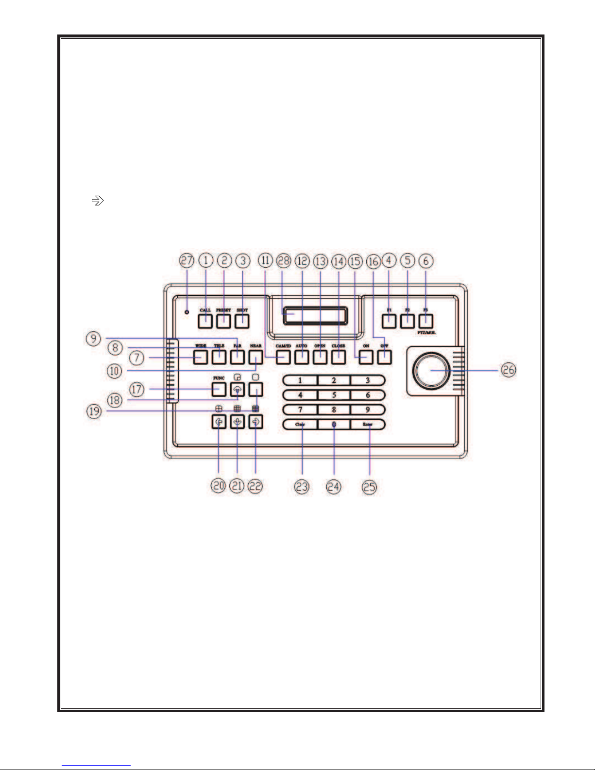
The Sketch of the Front Panel and Description of Buttons (Figure 1)
Figure 1
1!CALL"To call the preset position.
2!PRESET"To set the preset position.
3!SHOT"To call cruising track.
4!F1"Auxiliary control buttons.
5!F2"Auxiliary control buttons.
6!F3"Switching control between intelligent speed dome and multiplexer.
7!WIDE"To a wide angle.

3
8!TELE"To turn to a telescopic range.
9!FAR"To make focus far manually.
10!NEAR"To make focus near manually.
11!CAM/ID"Select address of the intelligent Speed Dome.
12!AUTO"To control auto-horizontal rotation for pan/tilt.
13!OPEN"To open iris.
14!CLOSE"To close iris.
15!ON"Switch on the setting of function.
16!OFF"Switch off the setting of function.
17!FUNC"Set special function of the system together with other buttons.
18!PIP#up arrow$"Show picture of the camera in PIP mode (Picture-in-Picture).
19!FULL SCREEN"Show picture of the camera in full screen.
20!3×3#left arrow$"Show picture of the camera in 9-frame.
21!2×2#down arrow$"Show picture of the camera in 4-frame.
22!4×4#right arrow$"Show picture of the camera in 16-frame.
23!CLEAR" To clear inputted data.
24!0-9" Number key.
25!Enter"To confirm.
26!joystick"control the upward, downward, leftward and rightward speed motion of the speed dome.
3D Joystick twist to zoom in and out (15-AU50H)
27!Power LED
28!LCD
 Loading...