

Spruce AIRaider Installation & Operating Instructions Manual
Doc. No. IN031
Rev. C
Page 1 of 19
Installation &
Operation Manual
All Residential and
Small System Models
(Except EZ95)
3 Saber Way
Ward Hill, MA 01835

Table of Contents
Doc. No. IN031
Rev. C
Page 2 of 19
1. PRE-INSTALLATION
1.1. Safety Maers
1.2. Water Flow Requirements
1.3. Unpacking and Locating System Components
1.3.1. Unpack All System Components
1.3.2. Locate All Components
1.4. Use Qualified Technicians
1.5. Full Water Test
2. INSTALLATION INSTRUCTIONS
2.1. System Location
2.2. Readying the AIRaiderTMfor Installation
2.3. Plumbing Hook-up
2.4. Electrical Hook-up
2.5. Vent Line Installation
2.6 Air Filter
2.6.1 Remote Air Intake
2.7. System Start-up
2.8. System Check
3. RETESTING
4. MAINTENANCE
4.1. Six-Month Service (recommended)
4.2. Annual Service (required)
3
3
4
5
5
5
5
5
7
7
7
9
10
13
14
14
14
15
16
16
16
17
5. TROUBLE SHOOTING
LIMITED WARRANTY
Table of Figures
Figure 1 – Typical System (433 & 321)
Figure 2 – Bypass/Solenoid Assembly
Figure 3 – Diagram of Installed System
Figure 4 – Water Connections
Figure 5 – Pressure Gauge and Pressure Tank
Figure 6 – 433 Wiring Diagram
Figure 7 – 321 Wiring Diagram
Figure 8 – Vent Line Connection
Figure 9 – Vent Line Installation (2 inch)
Figure 10 – Vent Line Intsallation (3 inch)
Figure 11 – Air Intake Connection
Figure 12 – Air Filter
Figure 13 – Installed AIRaider
TM
18
19
6
7
8
9
9
11
12
13
13
13
14
14
14

Doc. No. IN031
Rev. C
Page 3 of 19
1. Pre-Installation
The AIRaiderTMSystems are diffused bubble aeration systems for the removal of radon and other VOCs from
residential and municipal water supplies. This installation/operation manual is designed to guide professionals
through the safe and proper installation of the AIRaider
Before beginning the installation of the AIRaider
They are:
1. Safety
2. Installation site requirements
3. Inspection of System components
4. Qualified Technicians are necessary
5. Knowledge of all contaminants in the water
TM
1.1. Safety Maers
TM
Systems.
System, there are 5 items to be considered.
Safety is the most important step in the installation process. Never perform any step of the installation that
you are not qualified to perform (i.e. electrical or plumbing hook up). It is important that you read through
the entire manual prior to beginning the installation. When performing the installation, work slowly and
deliberately. Follow all instructions carefully and never take shortcuts. Our team of technicians are available
to answer your questions at 800-355-0901.
WORK SAFELY!

Doc. No. IN031
Rev. C
Page 4 of 19
1.2. Water Flow Requirements
The standard residential AIRaiderTMSystems are designed for use with water flows up to 20 gallons per
minute(GPM).* The system should be installed with an outflow ball valve. If higher/lower system outflow is
needed, open/close the ball valve by the amount necessary to balance the system. The well pump output must
TM
produce at least 1 GPM more than theoutput of the AIRaider
(i.e. well output = 8 GPM ; AIRaiderTMoutflow
seing = 7 GPM) for proper system performance. If the well pump output is less than the system output the
AIRaider
TM
will run dry and possible damage may occur. To preveent this from occuring the water flow rate
must bedetermined before the system is installed.
*Some AIRaiderTMSystems are not recommended for high flow residential properties. Repressurization systems (except for the
AIRaider
if assistance is needed for system selection.
M
5
T
9
EZ
are sold separately). Proper repressurization system sizing is required to meet water flow needs. Consult manufacturer
In order to determine available water flow rate the following are needed:
· Garden Hose
· Five Gallon Bucket
· A Stop Watch or Watch with a Second Hand
Or
· A Water Flow Meter
Household water use must be discontinued during the following flow rate test.
Mid-Range Flow Rate Test:
1. Aach garden hose to the drain connection on the base of the well pressure tank.
2. Open the drain valve and run water for 15 minutes.
3. Aer 15 minutes, check the pressure gauge on the well system. Adjust the drain valve (open or close) as
needed to maintain the required running system pressure (constant pressure on gauge) with the well pump
running continuously.
4. Run for 5 minutes while ensuring that the pressure is not fluctuating.
5. Run water from the hose into a five gallon bucket. Using a stop watch, time how many seconds it takes to fill
the bucket (X sec.).
6. Determine the GPM by dividing 60 seconds by the number of seconds it took to fill the bucket (X sec.).
Multiply the answer by 5 gallons. This gives you the GPM. GPM = ( 60 / X ) x 5
7. Repeat steps 5 and 6 and average the 2 numbers. The answer is the well pump output in gallons per minute.
It is recommended that this number be indelibly recorded in an obvious location, together with the date of test,
TM
as it will be required when seing the AIRaider
the well pump system or the AIRaider
TM
System.
System and may be required for future troubleshooting of

Doc. No. IN031
Rev. C
Page 5 of 19
1.3. Unpacking and Locating System Components
1.3.1. Unpack All System Components
Remove all packing material and discard appropriately away from the work area.
1.3.2. Locate All Components
Check to ensure all components are intact and included in shipment (See Figures 5 and 8).
Included Component List (may vary with order)
· Tank Assembly
· Control Panel* and Float Switches
· Jet Pump and Bladder Tank assembly**
· Brass – Bypass/Solenoid assembly, pump brass, and tank brass***
· Installation Kit – hoses, hose clamps, pressure gauge, manual, etc.
* Models 211 and 321 do not come equipped with a control panel
** Pump and Tank packages are sold separately and will vary with the order.
*** Standard systems are equipped for a ¾” plumbing connection. Please specify plumbing connection requirements when ordering.
1.4. Use Qualified Technicians
A Licensed Plumber, Electrician, Contractor and/or Certified Water Treatment Specialist may be required to
install the AIRaider
accordance with the National Fire Protection Association’s (NFPA)”National Electrical Code, Standard #70”current edition-for all commercial and industrial work. All wiring must be performed by a qualified and
licensed electrician. Check your Local and State Code and Licensing requirements. Failure to follow the
instructions may lead to poor system performance and/or possible system damage.
TM
System in accordance with the installation instructions. All wiring must be performed in
The Installation must comply with all applicable Local and State Codes
and NFPA National Electrical Code, Standard #70.
1.5. Full Water Test
A full Water Sample Analysis must be performed to determine the quality of the water that requires treatment.
In many water supplies, contaminants other than Radon are present and may need to be pre-treated in order
for the AIRaider
some other VOCs. The Aeration Process employed by the AIRaider
systems can worsen problems due to iron or manganese contaminants in the water supply. For optimal
removal of Radon or other VOCs, other contaminants such as iron, or manganese must be removed before the
water supply enters the AIRaider
TM
to work properly. The AIRaiderTMSystem is only effective for the removal of Radon and
TM
System.
TM
System and other Radon removal
Failure to remove other contaminants can reduce the effectiveness of the system
and may result in system damage.
Doc. No. IN031
Rev. C
Page 6 of 19
2. Installation Instructions
OVERVIEW
Now you are ready to begin the installation process. The eight steps to properly install the AIRaiderTMSystem
are listed below. Read all components of each step prior to beginning the actual installation.
1. System Location
2. Readying the System for Installation
3. Plumbing Hook Up
4. Electrical Hook Up
5. Vent Line Installation
6. Remote Air Intake Installation
7. System Start Up
8. System Check
SAFETY TIP: Do Not undertake any step for
which you are Not Qualified
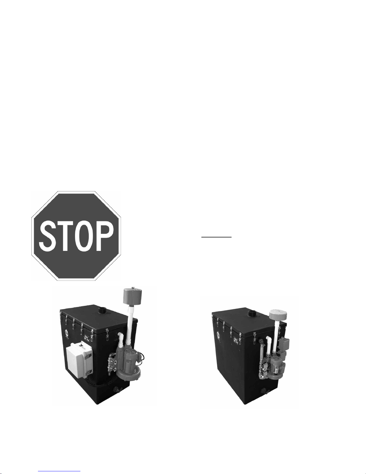
AIRaider 433
(Repressurization systems not shown. Sold separately.)
AIRaider 321
Figure 1
Typical System
 Loading...