

SPRSUN CGK/C-XX(L) Series, CGK/C-XX(LHC) Series, CGK/D-XX(L) Series, CGK/D-XX(LHC) Series, CGK/C-XX(H) Series User Manual
...
Heat Pump User Manual
Comprehensive version
(EVI heat pump and High temp. heat pump)
Version: CG2017111601
This manual is suitable for below heat pumps:
No Abbreviations Details Model
1 EVI-HW EVI air source heat pump hot
water series
CGK/C-XX(L),
CGK/D-XX(L)
2
EVI-HH EVI air source heat pump
heating + hot water series
3 EVI-HC EVI air source heat pump
heating and cooling series
4 HT Air source high temperature
heat pump
Note: Abbreviations name will be used in the below content, pls check the
related content for your heat pump referring to the form above.
CGK/C-XX(L),
CGK/D-XX(L)
CGK/C-XX(LHC),
CGK/D-XX(LHC)
CGK/C-XX(H),
CGK/D-XX(H)

Contents
Part 1. Before use …….…………………………………………………2-6
A. Attentions ...............................................................................................2
B. Installation ............................................................................................4-6
Heat pump installation location and attentions……………………………….….4
Installation diagram and tips…………………………...………………………...5
Pre-stat up………………………………………………………………………..6
Part 2. Use …………………………………………….….……………….7-21
Operation and display…………………………………………………..…….9-12
Data query and setting……………………………………………………...…..13
Error code………………………………………………………………………14
Working modes…………………………………………………………………19
Electrical component controlling……………………………………….………21
Part 3.Maintenance and Reparing ………………………………...23-26
Warranty card………………………………………………………………...26
P1
Part 1 Before Use
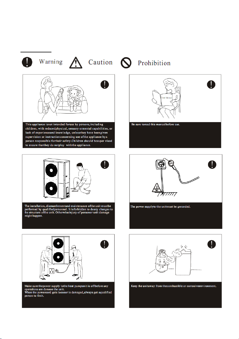
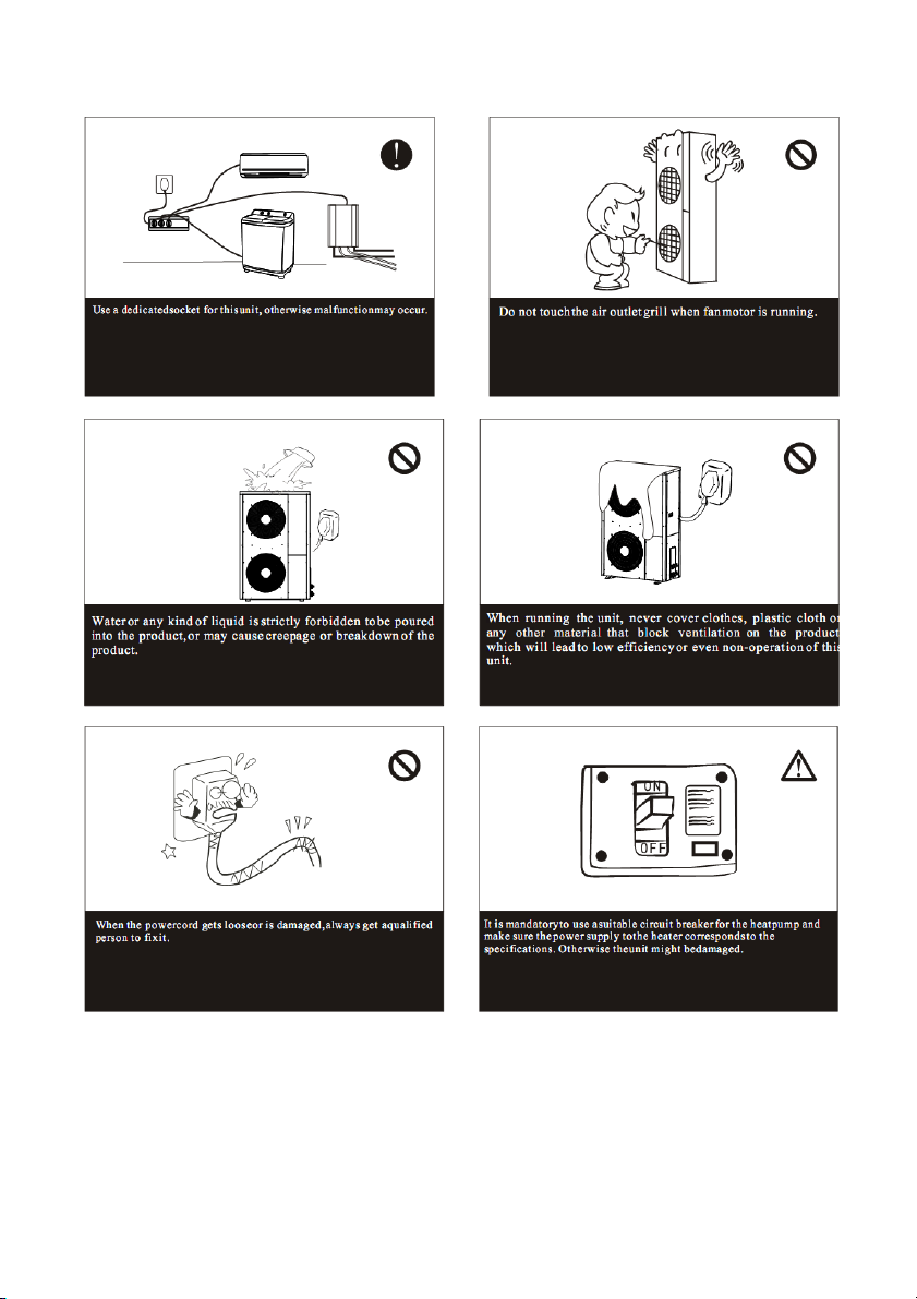
Attentions
P2
P3
2.Installation
A. Heat pump installation location and attentions
*. Heat pump is not allowed to be installed in the place where combustible gas
may leaks.
*. Heat pump is not allowed to be installed in the place where there is oil or
corrosion gas released.
*. Heat pump should be installed in a open space, and good ventilating.
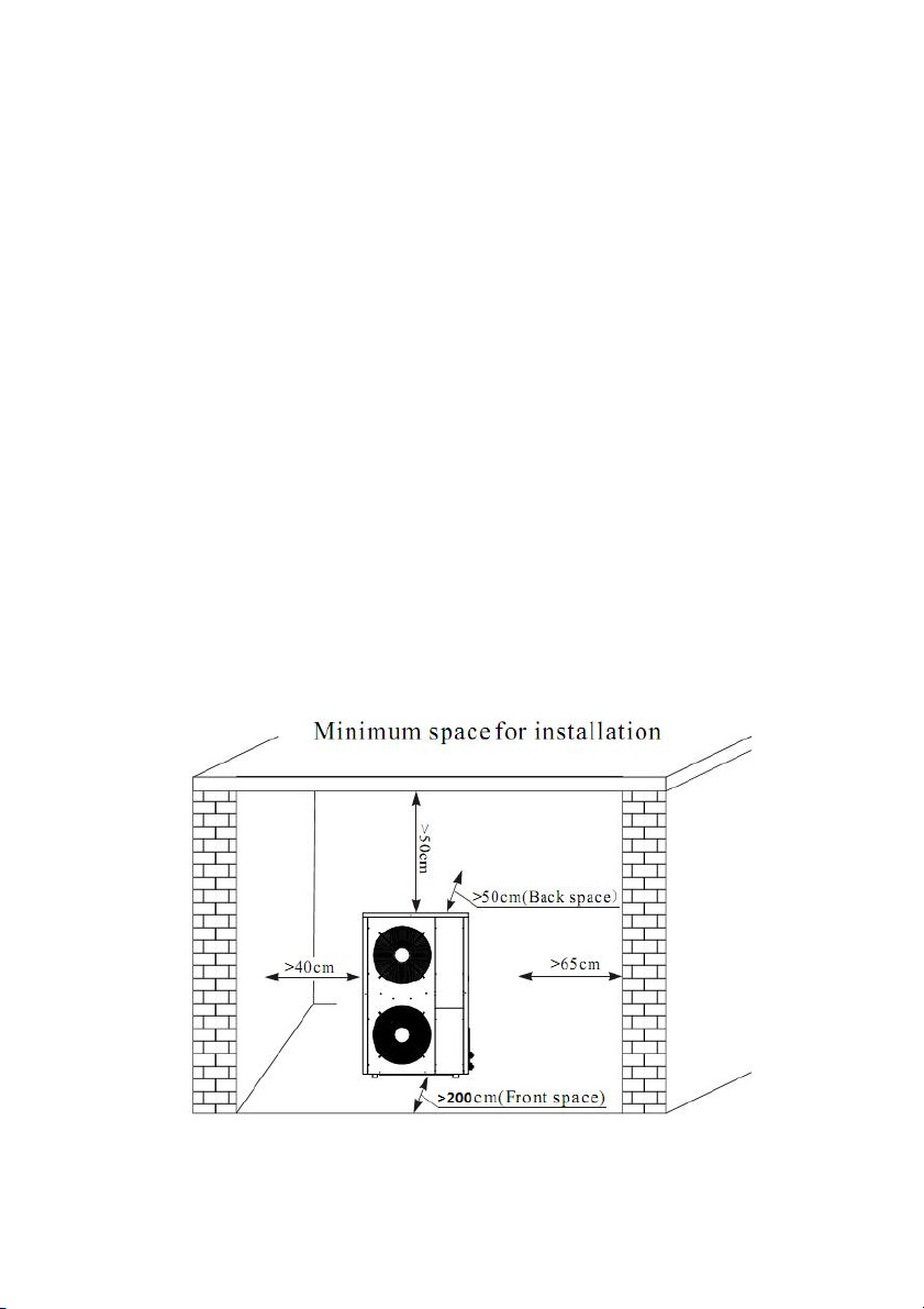
*. Heat pump each side to wall or barrel should be keep certain distance, air
outlet to barrel distance should ≥2m, air inlet distance to wall or barrel≥0.5m,
bottom distance to ground ≥0.5m, other side distance should be enough for
installation or repairing.
*. Heat pump should be installed on concrete basic or steel bracket, and
anti-shock pad should be put between heat pump and basic or bracket. Then use
expansion bolt to fix heat pump on bracket.
* Water drainage pipe and ditch should be set around heat pump and water pipes
and water tank. When testing or repairing, maybe need drain plenty of water, and
when heat pump is working, there are some condensed water flow down.
B. Installation diagram ( it is only for reference,the actual installation shall be
based on actual project)
P4

* for hot water and floor heating
*for heating/cooling
P5

Tips for installation related to the water pipe part:
*Install a valve at the highest point of each water circulations for releasing air
from water system.
* A Y filter is very important in front of circulating water pump of heat pump.
* If more heat pumps installed in one water pipe system, the connection of these
heat pumps can’t be in series, only can be in parallel or independent.
C. Pre-start up
1.Checking before pre-start up
* Check if the water pipe are connected well and if there is any leakage. The
water supply valve are open.
* Make sure the water flow is enough and meet the demand of the heat pump
selected and water flow smoothly without air . In cold area, pls make sure that
the water flow is without freezing
* Check if the power cable is connected well and properly grounded.
* Check if fan blade is blocked by the fixing plate of fan blade and fan blade
protecting grill.
* Check if the tank has been filled with water or enough water volume that can
meet the demand of heat pump running
Pre-start up
After check completely and confirm no problem for installation, the unit can be
power to start up .
After connect power supply, heat pump delay 3 mins to start. Check carefully
is there is some abnormal noise or vibration or if the working current is normal
or if water temp increasing is normal.
After the unit is working properly for 10 minutes without any problem, then the
pre-start up is usefully completed. If not, pls refer to Service and Maintenance
Chapter to solve the problem.
P6
Part 2. Use
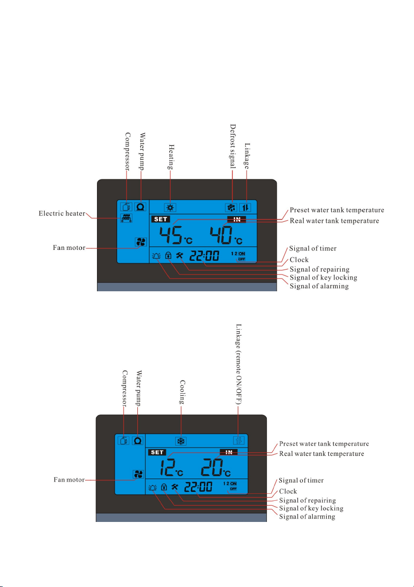
Operating panel display
EVI-HC
A. Heating mode
B. Cooling mode
P7

EVI-HH
A. Only hot water mode
B. Heating + hot water mode
P8

EVI-HW
HT series
P9

Buttons function
↓ ↓ ↓ ↓ ↓
Clock M + - power
“Power” button
2.1.1 Under unlock state, press this button for 1second, can turn on and turn off
heat pump.
2.1.2 Under other state, press this button, can return main interface.
2.1.3 Under locking state, press this button for 5 seconds, can unlock buttons.
“M” button
Under main interface, press “M” button, can query the working status
parameters
“+”and “-“ button
2.3.1 Turns page, change value
2.3.2 Combine with “M” button, can query and set parameter
2.3.3 Under power on state, press “+”and “-“button, can set current working
mode water temperature (except heating + hot water mode).
“Clock” button
2.4.1 Press this button for 10seconds, enter clock setting interface
2.4.2 Press this button, can enter timer of ON/OFF setting, combine “+”and
“-“button, can set timers.
Operating
Operating panel get electricity
When heat pump power supply is supplied, operating panel and PC board will
get electricity, then display panel displays, background light is very weak, all
buttons are locked now, any touching is invalid.
Unlock buttons
Press “power” button for 3sec, when hear “Du” voice, move finger, now
background light is strong, all buttons are unlocked, the lock symbol disappear.
P10

(if there is not operating on buttons for 60sec, buttons will be locked
automatically, and displays lock symbol)
Turn on/off heat pump.
Press “power” button, if operating panel shows off state, will turn on heat pump.
If operating panel shows on state, will turn off heat pump.
Water tank temperature setting (L3 or L4)
Except EVI-HH and HH series, other series have two way to set water tank
temperature:
Way 1:
Under on state and main interface, press “+” and “-“ button, can adjust current
working mode water tank preset temp. The preset water tank temp is the left one
temperature, the real water tank temp is the right one temperature. When setting,
the left temp will change, and display L3 or L4 below it.
Way 2:
Refer to “Table 3: user parameters query and setting” in P15. All user parameters
can be set by the same way. Floor heating water temperature only can be set by
this way.
Parameters query and setting operation
① Working status parameters and history error code query
How to enter? Under main interface, press ”M” button, can query the working
status parameters and history error codes
Working status parameters (table 1)
P11

Table 1: heat pump working status parameters query
Code Meaning Note
A0 Water tank temperature
A1 Outlet water temperature
A2
A3
A4
Air heat exchanger 1 lowest
tube temp
Inlet gas temperature of
compressor 1
Outlet gas temperature of
compressor 1
Same meaning for all series
Same meaning for all series
Same meaning for all series
A5 Ambient air temperature Same meaning for all series
A6 Inlet economic unit 1 Same meaning for all series
A7 Outlet economic unit 1
A8
Return water temperature of
water tank
Inlet water temp For EVI-HC
For EVI-HW and HT series
For EVI-HH and HH series
Floor heating water temp
(displayed on main interface, the
left one temperature)
A9 Compressor 1 current Same meaning for all series
For HW and HH and SP-H series,
rated heating capacity less than
52KW models
Same meaning for all series
A10
A11
Primary electronic expansion
valve opening degree 1
Secondary electronic expansion
valve opening degree 1
A12 After throttling1 temperature
A13 Air heat exchanger 2 lowest Same meaning for all series
P12

tube temp
A14 Outlet gas temperature of
Same meaning for all series
compressor 2
A15
Inlet gas temperature of
compressor 2
Same meaning for all series
A16 After throttling 2 temperatures
A17 Inlet economic unit 2
A18 Outlet economic unit 2
A19 Compressor 2 current Same meaning for all series
A20
Primary electronic expansion
valve opening degree 2
For HW and HH and SP-H series,
rated heating capacity less than
52KW models
A21
A22
Secondary electronic expansion
valve opening degree 2
Air conditioning (floor heating)
inlet the water temperature
Same meaning for all series
A23 User return water temperature
E1~
E6
History error code Same meaning for all series
Note:
1.A23 return water temperature:
It is the return temperature of hot water mode, the temp sensor need to be
installed in the water tank on the return pipe, used to control the return valve;
2. about water tank temp sensor, installation position in each series is
different.
A. EVI-HW: should be installed in hot water tank by installer
B. EVI-HH series: hot water tank temp sensor should be installed in hot water
tank by installer. (Floor heating water temp sensor should be installed in floor
heating water tank or on floor heating system return water pipe)
C. EVI-HC series: water tank temp sensor has been installed on inlet water pipe
by factory (if project has A/C water tank, installer can move the sensor to tank
from heat pump)
P13

Table 2: Error code
Code Meaning Method
Er 01
Wrong phase error
Exchange phase sequence
Er 02 Lack phase error
Er 03 Water flow switch error
Er 04
Er 05 System (1) High pressure
Er 06 System (1) Low pressure
A/C side of the water flow
switch
Er 07 System (2) High pressure
Er 08 System (2) Low pressure
Er 09 Communication error
Er10 Tank temp sensor
Er 11
Er 12
Time limit for locking heat
pump reached
System (1)
pressure of compressor 1 is
Outlet gas
Check the power supply
Check the hot water side of the water
flow is sufficient or the water flow
switch wiring, such as damage please
replace
Check the hot water side of the water
flow is sufficient or the water flow
switch wiring, such as damage please
replace
Check water flow is too small; check
the dust of fin heat exchanger
Check water flow is too small; check
whether the refrigerant leak
Check the PC board and control panel
line is connected, if damaged please
replace
Please cancel setting time of
running
P14

too high
System (2)
Er 13
pressure of compressor 2 is
too high
Er 14 Throttling temperature 1
Er 15 Throttling temperature 2
Er 16
Er 17
Er 18
Er 19
Air heat exchanger 1 coil
temp sensor
Air heat exchanger 2 coil
temp sensor
Outlet gas temp sensor 1 of
compressor error
Outlet gas temp sensor 2 of
compressor error
Outlet gas
Check the sensor contact is good;
replace the temp sensor
as above
as above
Er 20 Ambient air temp sensor error as above
Er 21
Er 22 HE
Er 23
A/C Return water temp
sensor
outlet water temp sensor as above
Inlet gas temp sensor 1
Er 24 Inlet gas temp sensor 2
Er 25
Er 26
Er 27
Er 28
Er 29
The economic unit 1 inlet
the sensor error
The economic unit 2 inlet
the sensor error
The economic unit 1 outlet
the sensor error
The economic unit 2 outlet
the sensor error
Compressor 1 current too
high protection
Er 30 Compressor 2 current too
as above
as above
as above
as above
Check the current and voltage are
stable
P15

high protection
Er 31 Water level switch error
Ambient temp too low
Er 32
protection
Outlet water temp too high
Er 33
error at heating mode
Air conditioning supercooling
Er 34
protection
Return water temp sensor error
Er 35
of water tank
Hot water symbol flashing Anti-freeze protection for hot water side
Heating symbol flashing Anti-freeze protection for heating side
Check the wiring contact is good; replace
the pressure switch
Beyond the normal operating temperature
range of the heat pump
Check the sensor contact is good; replace
the temperature sensor
Check if the air conditioning water pump
is low water
Check the sensor contact is good; replace
the temperature sensor
②User parameters query and setting (both ON and OFF state can set)
How to enter?
◆ Under main interface, press “M” for 3seconds, enter user parameter query
interface, then press “+”and “-“ button , can query L0 to L9value.
◆ Under user parameter query interface, press “M” button, enter setting interface,
press “+”and “-“ button, to set the value of current parameter, press “M” button
again, return query interface.
◆ Under user parameters query interface and setting interface, if there is not
operation for 30seconds constantly, system will quit user parameter query or setting
interface automatically, and return to main interface, press “power” button can return
main interface too.
Table 3: user parameters query and setting
P16

Code Meaning
L0
L1
L2
L3
Compressor restart temperature
of hot water drop
Preset water tank temperature of
heating mode
Compressor restart temperature
cooling drop
Preset water tank temperature of
cooling mode
L4 Heating drop
L5 Heating set the temperature
Ambient air temperature below
L6
which electric heater is allowed
Setting
range
2℃─18℃
20℃─58℃
2℃─18℃
10℃─32℃
2℃─18℃
12℃─99℃
─30℃─35
℃
Factory setting
3℃
1. HT series: 75℃
2. EVI-HC series: 45℃
3. Other series: 55℃
5℃
12℃
5℃
45℃
0℃
to start
L7 Return water temperature
L8
Water compensate temperature
L9 Compressor current
20℃─80℃
20℃-80℃
0~48A
30℃
48℃(20℃ no need
water compensate)
0A(0A: will not detect
current)
Note:
L1, L3 is the water tank setting temperature . Water tank temperature is directly
displayed on PC board. The left side is the setting temperature, the right side is the
actual temperature.
For heating, User need put the temp sensor into blind tube which is installed on
water tank.
The pool temp sensor is installed on a titanium tube heat exchanger by factory
The water temp sensor of the heating and cooling mode is installed in the return pipe
of the heat pump by factory.
Other operation
P17

①Clock setting
A. At main interface, press “clock” button for 5 seconds, enter clock setting interface
B. At clock interface, press “clock” button, then “hour” flash, press “+”or “-”button,
can set hour.
C. After finish setting hour, press “clock” button, then “minute” flash, now press
“+”or“-”button,can set minute.
D. After finish setting minute, press “clock” button, to confirm clock setting, and
back to main interface.
E. At clock setting interface, if there is not operation within 30seconds, system will
confirm clock setting and back to main interface automatically.
F. At clock setting interface, press “power” button, can confirm current clock setting
and back to main interface.
②Timer setting and cancelling (ON/OFF timer)
A. At main interface, press “clock” button, enter timer group setting.
Now press “+”or“-”button, can switch timer groups, there are 4 groups ON/OFF
timer.
B. When group 1 ON timer flashing, press “clock” button, enter group 1 ON timer
“hour” setting interface, “hour” flash, then press “+”or“-”button,then can set “hour”
for group 1 ON timer.
C. After finish setting “hour”, press “clock” button, then “minute” flash, then press
“+”or“-”button,can set “minute” for group 1 timer.
D. After finish setting group 1 ON timer “minute”, press “clock” button, enter group
1 OFF timer setting, same way like ON timer setting.
E. After finish setting group 1 ON/OFF timer, press “clock” button, confirm group 1
setting, and enter group 2 ON/OFF timer setting, same way like group 1 setting.
F. At timer interface, if there is not operation within 30seconds, then confirm current
timer setting, and back to main interface (this setting can be remembered if
electricity is cut off)
G. At timer interface, press “power” button, confirm current timer setting, and back
to main interface.
H. Other groups ON/OFF timer setting are same way like group1.
Remarks: groups 1 and 2 are heat pump ON/OFF timer, group 3 is return water timer,
group 4 is cool water compensating timer.
P18

group 3 and 4 only valid for EVI-HW, HT series.
I. How to cancel timer?
At timer interface, press “clock” button for 5seconds, when the ON and OFF signal
disappear, then press “power” button to confirm, can cancel current group ON/OFF
timer.
③③③③Forced defrosting
◆ At ON status, press “-” for 3seconds, enter forced defrost.
◆ To quit forced defrost, there are two ways.
a. Automatic quitting: when defrost time reach preset quitting temperature, can quit
forced defrost.
b. Forced quitting: Press “power” button,after power off, 3minutes later, will quit
forced defrost completely.
④④④④Remove history error code
At the interface of query history error code, press “power” and “M” button together
for 5seconds, can remove all the history error code.
⑤⑤⑤⑤Change working mode
Press “+” button for 5seconds, can change the working mode For EVI-HC series,
change working mode between heating mode and cooling mode.
For EVI-HH series, change working mode between hot water mode and heating +
hot water mode.
C. Working mode
1. EVI-HW, HT series
The three series mainly used to supply hot water, (sometimes used for house
heating), have only one working mode: hot water mode.
1.1 The unit start and stop based on the hot water tank temp. and setting temp.
2. EVI-HH series
The two series mainly used to supply hot water and heating house, have two
working mode: Hot water mode and hot water + heating mode.
2.1 Hot water mode controlling, the unit start and stop based on the hot water tank
temp. and the setting temp.
2.2 Hot water + heating mode controlling
2.2.1 Hot water mode: working same as 2.1
P19

2.2.2 Heating mode
The unit start and stop based on the heating return temp. and the setting temp.
2.2.3 Hot water + floor heating controlling logic
◆ Hot water is priority, before hot water reach preset temp, 3-way valve doesn’t
have electricity
◆ When hot water reach preset temp, heat pump stop, then check heating side
water temp automatically, if heating side water temp doesn’t reach preset temp, then
3-way valve will get electricity, and meanwhile heat pump start. When heating
system water temp reach preset temp, heat pump stop to standby. In the process, if
check hot water tank temp dropped lower then setting temp., then heat pump stop
and 3-way valve loss electricity, then heat pump restart to heat hot water.
3. EVI-HC series
The three series are all heating and cooling type. User can change the working mode
between heating mode and cooling mode.
3.1 Heating mode
The unit start and stop based on the setting temp. and real water tank temp.
3.2 Cooling mode
The unit start and stop based on the setting temp. and the real water tank temp.
4. Defrosting:
Defrost only valid at heating or/and hot water mode.
When defrost, the display panel will display defrost symbol.
Fan motor doesn’t work.
Compressor stops first, then start.
Circulating water pump doesn’t stop.
D. Each electrical component controlling
1. Compressor (installed inside heat pump)
1.1 Compressor start / stop according to water tank (or heating system) real
temperature and preset temp.
1.2 After compressor stops, should need at least 3min, then it can restart again.
1.3 After compressor start, should work at least 2min first, then can stop. (Except
turned off or there is error).
1.4 There is not 3min protection for the first time starting.
P20

2. Four - way valve (installed inside heat pump)
2.1 At heating or hot water mode, 4-way valve lose electricity.
2.2 When cooling or defrosting, four-way valve get electricity.
2.3 Four way valve delay 2min change direction after compressor stop when change
working mode.
2.4 When defrosting and forced defrosting, 4-way valve get electricity.
3. Circulating water pump
3.1 EVI-HW, EVI-HC, HT series:
Circulating water pump start / stop together with compressor.
3.2 EVI-HH series
If change to hot water mode, circulating water pump start/stop together with
compressor.
If change to hot water + heating mode, circulating water pump doesn’t stop.
4. Fan motor (installed inside heat pump)
4.1 Normally, fan motor start in advance than compressor, and stop at the same time
as compressor.
4.2 When defrosting, fan motor doesn’t work.
5. Auxiliary electrical heater
5.1 Starting conditions::::
5.1.1 At heating or hot water mode
5.1.2 Ambient temperature ≤ L6
5.1.3 Water tank temperature < water tank setting temp. – L0
5.1.4 Low level switch connects.
When all of above conditions are met, electric heater starts.
5.2 Stopping conditions:
5.2.1 Water tank temp ≥ water tank setting temp..
5.2.2 Water tank temp sensor damaged and controller show error code.
5.2.3 Ambient temp ≥L6+2℃;
5.2.4 Water level switch has error
5.2.5 Low level switch disconnects
Any of above condition is met, electric heater stops.
5.3 When defrosting, forced defrosting, secondary anti-freeze, electric heater is
forced to start.
P21

5.4 Except there is water level error, hot water tank temp sensor error, when there
is other temp error, high and low pressure error protection, electric heater will start.
Remarks: EVI-HH series, only hot water side has electric heater function, heating
side doesn’t have.
6. Three-way valve
6.1 Only EVI-HH and HH heat pump have three-way valve function. Installer need
install three-way valve on outlet water pipe of heat pump.
6.2 When switch to hot water side, 3-way valve lose electricity. When switch to
heating side, 3-way valve get electricity.
6.3 Before 3-way valve switch the direction, circulating water pump should stop first
10 seconds in advance.
7. Return water valve
Only EVI-HW, HT series has return water valve function.
7.1 Condition of return water valve open (all below condition should be met):
7.1.1 Low water level switch connects
7.1.2 Water tank temp ≥L7 + 5
7.1.3 Return water temp ≤ L7 – 5
7.2 Condition of return water valve closes (any below condition met):
7.2.1 Low water level switch disconnects
7.2.2 Water tank temp < L7 + 5
7.2.3 Return water temp > L7
8. Linkage switch
8.1 Linkage switch is input OF/OFF signal, heat pump can be turned on/off by the
signal.
8.2 When operating panel is under on state, if linkage signal is on, heat pump keep
on state. If linkage signal is off, heat pump will be turned off.
8.3 When operating panel is under off state, if linkage signal is off, heat pump keep
off state. If linkage signal is on, heat pump will be turned on.
9. RS485 Connection
P22

Part 3. Maintenance and repairing
A. Daily maintenance
Heat pump is high automatic equipment, if can check and maintain periodically, the
stability and lifetime of heat pump will increase greatly.
1. When using and maintain the heat pump, please note: all security device have
been set before leave factory, please don’t adjust anymore.
2. Check if power cable and other cables connection is firm, if electrical unit work is
abnormal, if yes, repair or replace at once.
3. Check periodically if water system leaks water, if insulation damaged.
4. Check if the air around is clean and dry, if ventilation is good.
5. Don’t put debris around heat pump, avoid blocking air inlet and outlet.
6. If need stop heat pump for long time, should drain the water in the system, and cut
off the power supply. Before restart, check the system completely.
7. When there is error codes, or heat pump work abnormally, please call local
servicer to repair.
B. Some error code and repairing
When below error happen, controller will alarm and display error code.
Error Possible reason Method to repair
1. Check if water tank temp probe
is installed correctly
2.1 Release air from highest
position of circulation.
2.2. Open Y type filter to check if
there is impurity on the net.
3. Drain refrigerant and vacuum
and refill refrigerant according to
nameplate.
1. Check leaking point and repair
and refill refrigerant
2. Change fan motor or blade
3. Wash fin of air heat exchanger or
High pressure
error
Low pressure
error
1. Real water temp is too
high but probe can’t
detect real temp
2. Water flow is too small
3. Refrigerant is
excessive
1. Lack of refrigerant
2. Fan motor doesn’t run
3. Air flow is blocked
P23

1. Lack of refrigerant
2. Water pump is too
Outlet gas temp
too high error
Outlet water
temp too low
protection when
cooling
Outlet water
temp too high
protection when
heating (hot
water)
Compressor
current is too
large
small
3. Water pipe is too small
4. Air entered water
system
1. Circulating water
pump is too small
2. Air entered water
system
3. There is impurity in
water filter.
1. Circulating water
pump is too small
2. Air entered water
system
3. There is impurity in
water filter.
1. The current detector is
damaged
2. Compressor damaged
3. Compressor doesn’t
start
C. Other problem and repairing
remove barrier close air inlet or
outlet.
1. Repair leakage and refill
refrigerant
2. Change a bigger water pump
3. Change bigger size water pipe
4. Release air in water system
1. Change a bigger water pump
2. Release air from water system
3. Clean the filter
1. Change a bigger water pump
2. Release air from water system
3. Clean the filter
1. Change the detector
2. Change compressor
3. Check if the compressor cable is
loose
No Error Possible reason Method
1
Heat pump
doesn’t run
1. Power supply cable is
loose
2. The fuse of power
P24
1. Cut off the power
supply to check and
repair.

supply is fused. 2. Change the fuse.
Heating capacity
2
is too small
Compressor
3
doesn’t run
Compressor noise
4
is loud
Fan motor
5
doesn’t run
Compressor run,
6
but not heat
1. Refrigerant is not
enough
2. Water system insulating
is not good
3. Air heat exchanger is
dirty
4. Water heat exchanger
scaled
1. Power supply has error
2. Cable connecting is
loose
3. Compressor is overheat
1. Expansion valve
damaged lead to liquid
entering compressor
2. The internal parts of
compressor damaged
3. Compressor lack of oil
1. Fan blade fixing screw
is loose
2. Fan motor damaged
3. Fan motor capacitance
damaged
1. There is not refrigerant
at all
2. Compressor damaged
P25
1. Check leakage and
repair and refill gas
2. Improve the
insulation
3. Clean air heat
exchanger
4. Clean water heat
exchanger
1. Check reason and
solve
2. Check loose and
repair
3. Check reason and
repair
1. Change expansion
valve
2. Change compressor
3. Compensate oil for
compressor
1. Tight the screw
2. Change fan motor
3. Change the
capacitance
1. Check leakage and
repair
2. Change compressor

Warranty card
Product model: Bar code:
Buyer Address
Invoice No. Date
Repair date Repair record Repairer
Items of warranty:
1. Warranty term: ; Within
warranty, any problem because of quality, we repair for free.
2. When need repair, please show the warranty card and invoice of order
or other proof.
P26

3. We don’t afford the problem that is caused by re-fitment or adding
other function by user.
4. Warranty card and invoice or other purchasing proof will be invalid if
alerted.
5. Please keep the warranty card and invoice or other purchasing proofs
good, we will not supply service if these documents are lost.
6. We will not repair for free for below condition:
①without proof;
②Errors caused by re-fitment or not correct operating;
③Damage caused by not professional people operating;
④faulty by moving or falling;
⑤Faulty caused by natural disaster.
Product Model:…………………………………
CERTIFICATE
Bar code:………………………………………….
Checking result:…………………………………
P27
 Loading...