

Page 1

ACT5prox
Operating & Installation Instructions
18-00042
Page 2

ACT5prox Operating and Installation Instructions
Installation Notes
• Remember to Factory Default the ACT5prox before programming
• Remember to place the supplied varistoracross the terminals of the door strike coil to protect the relay
contacts
• Don’t mount the ACT5prox units near RF sources (Eg mobile phones, radio transmitters, computer
monitors) or metal surfaces.
• Don’t power the unit from a switch-mode power supply. Use a linear regulated power supply.
• Never use the on-board relay to switch AC mains voltage. An external relay, electrically isolated from
the ACT5prox should be used for this purpose
• Remember to change the programming code.
• When ordering new cards or fobs specify ACTRFID. ACT5prox will NOT work with HID cards or
fobs.
Important
As with any Access Control system, always ensure there is an alternate means of escape in the event of
the unit failing to operate due to power loss or in the event of fire.
Product Specification
Number of Users 50 (50 unique PINs and 50 Cards)
Supply Voltage 12 - 24V AC or DC (linear PSU)
Current Consumption 60mA (nominal), 100mA (maximum)
Operating Temperature -10 to +50 degrees C
Door Open Time 0 - 255 seconds
Relay Contact Rating 5A / 500Vac
Controller Size Flush Mount 100 x 110 x 20 mm
Surface Mount: 100 x 110 x 35 mm
Controller Weight 200 grams
Water Resistance High IP67
Construction Rugged Polycarbonate housing with stainless steel keys
and potted electronics.
Ordering Information
Pin & Prox Reader: ACT5prox
Proximity Card: ACTProx ISO-B
Proximity Fob: ACTProx Fob-B
Proximity Half Shell Card: ACTProx HS-B
Proximity & Magnetic Stripe Card: ACTProx DUO-B
2
Page 3

ACT5prox Operating and Installation Instructions
30 Second Programming Guide
(For typical Standalone System)
1. Enter Programming Mode.
On the digital keypad press button
The LED will flash amber.
2. Change User 1 Code
On the digital keypad press button 0. Input 01 (for User 01). Input the new User 1
code (4 digits)
3. Add User 1 Card
On the digital keypad press button 5. Input 01 (for User 01). Present User 1’s card twice.
4. Change Programming code
On the digital keypad press button 0. Press
5. Exit Programming Mode
On the digital keypad press button
has been exited.
5. Record User Code and Card
Enter the details of the Users and their associated codes and card numbers on the User List at
the back of this manual.
. Input the programming code (default is 9999).
✘
. Input the new programming code (4 digits)
✔
. The LED turns red and programming mode
✘
The ACT5prox is now ready for normal use.
Note: The ACT5prox may be returned to its factory default condition at any time by entering the
programming mode and and pressing Button
three times.
✔
Unit C1, South City Business Centre,
Tallaght, Dublin 24, Ireland
Tel: 353-1-4662570 Fax: 353-1-4520427 UK Locall: 0845 300 5204
Web: http://www.accesscontrol.ie E-mail: tech@accesscontrol.ie
Copyright © 2007 Access Control Technology Ltd.
3
Page 4

ACT5prox Operating and Installation Instructions
Programming Summary
Code Function Default
0 Change PIN code 1234 – User 1, 9999 - Programming Code
1 Set Toggle Mode Off (Timed Relay)
2 Set Door Relay Time 5 seconds
5 Add User Card
6 Delete User’s Card
7 Delete Card Number
30 Card or PIN On
31 Card and PIN Off
32 Card and any PIN Off
40 Permanent Backlight On
41 Auto Backlighting Off
80 Check PIN User
81 Check Card User
ACT5prox Operation
The ACT5prox is a simple, easy-to-use access control unit combining digital keypad and proximity
technology. The unit supports up to 50 users, each with a unique PIN code and proximity card/fob.
Each unit is contained in rugged polycarbonate housing, with stainless steel keys and potted
electronics, allowing for indoor and outdoor installation. Keypad backlighting enhances the
ACT5prox functionality at night or in poor light conditions.
Programming the unit is achieved via the keys, LED and buzzer. Cards and PIN codes can be
programmed into the ACT5prox very quickly. ACT recommends that Users and their associated
PIN and Card are recorded in the User List at the end of the manual. Make copies of this sheet
and enter each Users details on it. This will allow users to be deleted later on, even if a card is lost or
a user forgets their PIN code. Blank User List forms can be downloaded from the Resource
Centre on the ACT website, www.accesscontrol.ie
A valid card or PIN will allow access through the ACT5prox unit. For maximum security, the unit
may be programmed to require all users to enter a PIN code after presenting a card.
4
Page 5

ACT5prox Operating and Installation Instructions
ACT5prox Programming
On the digital keypad press the button✘and input the programming code (initially 9999). The LED
will flash amber while in programming mode. To exit the programming mode either press button
do not activate any key for 30 seconds.
• If the LED flashes green during programming, then a card presentation is expected.
• If the LED flashes red, then a keypress is expected.
• While the ACT5prox is busy performing a task, (eg. Defaulting memory, adding cards), the
green led will turn on and the buzzer will sound an elongated tone.
Changing User PIN Codes: Enter Programming Mode, then Press
Step Keypad Entry Operation Example: Assign code 7529 to user 7
10 Change PIN codes
2 00-49 Enter 2 digit User Number 00-49 0 Change PIN codes
3 0000-9999 4 digit code – 0000 deletes User code 07 User 7
*Remember to update the user list document at the back of this manual after adding a PIN or Card
9999 Enter programming
✘
7529 PIN code
✘
Exit programming
✘
or
Adding Cards: Enter Programming Mode, then Press
Step Keypad Entry Operation
15 Add Card
2 00-49 First user to be assigned card
3 Present Card First Card in Batch (lowest number card) assigned to first user
4 Present Card Last Card in Batch (highest number card) assigned to last user
Cards may only be assigned to users that do NOT have a card already assigned. When adding cards to
the ACT5prox, check which users already have cards by using option 81 (see page 7).
Example: Assign card 0000200036 to user 21: Example: Assign card 0000200036 to user 21
Keypad Entry Operation Keypad Entry Operation
9999 Enter programming
✘
5 Add card 5 Add card
21 User 21 21 User 21
Present card Card number 0000200036 0000200036 Enter 10 digit card number
Wait 2 seconds 0000200036 Enter 10 digit card number
Present Card Card number 0000200036 ✘ Exit programming
✘
Exit programming
9999 Enter programming
✘
5
using the keypad:
Page 6

ACT5prox Operating and Installation Instructions
Change Programming Code: Enter Programming Mode, then Press
Step Keypad Entry Operation
10 Change Programming code (Default 9999)
2 Press
3 0000-9999 New 4 digit programming code
✔
Set Door Relay Time: Enter Programming Mode, then Press
Step Keypad Entry Operation
12 Set Door Relay Time – (default 5 seconds, maximum 255 seconds)
20 Buzzer sounds indicating timing… wait required period
3
✔
End setting Door Relay Timer
Set Toggle Mode: Enter Programming Mode, then Press
Step Keypad Entry Operation Example: Assign Toggle made to user 12
11 Set Toggle Mode
2 00-49 Enter 2 digit User Number 00-49 1 SetToggle Mode
3 0 or 1 0 = Relay Toggle, 1 = Relay Timed 12 User 12
9999 Enter programming
✘
0 Relay toggle
✘
Exit programming
Deleting Userʼs Card: Enter Programming Mode, then Press
Step Keypad Entry Operation Example: Delete user 10’s card
16 Delete User’s Card
2 00-49 First user to delete 6 Delete cards
3 00-49 Last user to delete 10 User 10
9999 Enter programming
✘
10 User 10
✘
Exit programming
Deleting Card Number: Enter Programming Mode, then Press
Step Keypad Entry Operation
17 Delete card number
2 10 digit card number 10-digit Card number with leading zeroes.
Eg. Card 54321, enter 0000054321
Check if User has no PIN Assigned: Enter Programming Mode, then Press
Step Keypad Entry Operation
1 80 Check if user has no PIN already assigned
2 00-49 User 0-49
Keypad will flash the green led and sound high-pitched tone if the user has NO
PIN code assigned. It will flash red and sound low-pitched tone, if the user has
a PIN code.
6
Page 7

ACT5prox Operating and Installation Instructions
Check if User has no Card Assigned: Enter Programming Mode, then Press
Step Keypad Entry Operation
1 81 Check for user with no card assigned
2 00-49 User 0-49
Keypad will flash the green led and sound high-pitched tone if the user has NO
card assigned. It will flash red and sound low-pitched tone, if the user has a card.
Programming ACT5prox Options Enter Programming Mode, then Press
Step Keypad Entry Operation
1 30, 31,32,40 or 41 2 digit option number
2 0 or 1 0=Off, 1= On
Option Function Default Operation
30 Card or PIN On When set, a valid Card or valid PIN will open the door.
31 Card and PIN Off When set, only users with both a Card and PIN are admitted. Cards
32 Card and any PIN Off In this mode, a valid card and any valid PIN code will open the
40 Permanent Off When set, the keypad illumination is always on. This option will
Backlight override option 41 (Auto Backlighting)
41 Auto Backlighting On When set, the keypad illumination is normally off, but will switch
are assigned to a particular user using the Adding Cards function
(function 5) and PINs are assigned using the Changing PIN Codes
function (function 0).
door. This mode allows all users to have a common PIN code to
use with their cards.
on in response to any key being pressed, or when a card is
presented or while in programming mode. This option is
overridden by option 40 (Permanent Backlight). To prevent any
illumination, turn off options 40 and 41.
Restoring Factory Defaults
Enter Programming Code followed by
If the Programming Code has been forgotten, it may be set to 9999 by:
1. Remove the power from the unit.
2. Remove link LK1 at the back of the unit.
3. Apply power to unit.
4. Replace link LK1.
5. Programming Code is now set to 9999.
Note: The keypad will not operate correctly without LK1 in place.
Defaulting memory takes 3-4 seconds. During this time, the buzzer will sound an elongated tone.
. This restores the ACT5prox to its default settings.
✔✔✔
7
Page 8
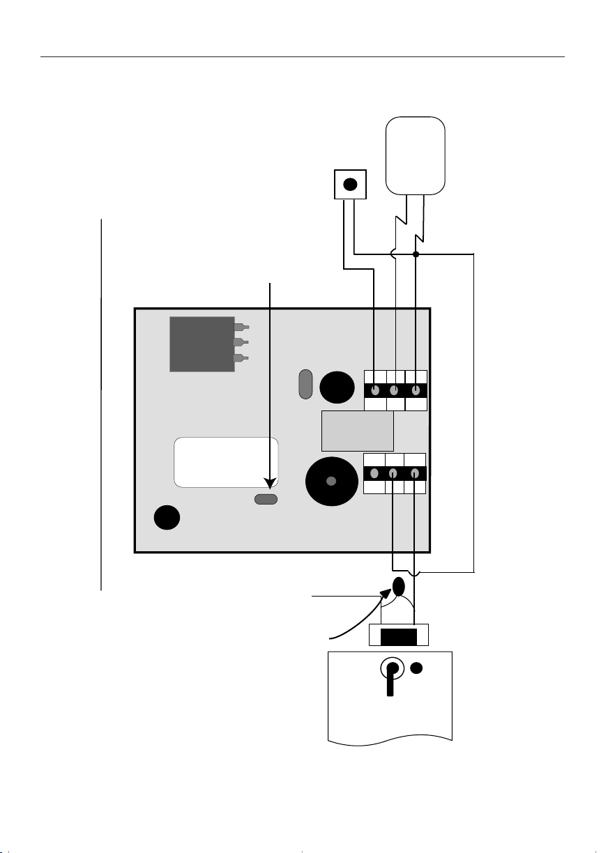
N/O
Comm
N/C
BATCH:
PRODUCT
SERIAL NUMBER
01XX-
ACT5prox
00XXX X
Note
:
The ACT5prox may be powered
from 12 or 24V AC or DC.
Door Release
Button
Power
Supply Unit
This illustration shows wiring
for normally de-energised
locks. If normally energised
locks are required, use the
N/C relay contacts .
Important!
Always Place Varistor
Across Lock Terminals
+12V
0V
12-24V
AC/DC
Push Button
0V
SCHRACK
12V = DC
5A/250V ~AC
LK1
Power up without link if
Programming code has been lost
ACT5prox Wiring Diagram for Door Strike Locks
Fig 1
ACT5prox Operating and Installation Instructions
8
Page 9

N/O
Comm
N/C
BATCH:
PRODUCT
SERIAL NUMBER
01XX-
ACT5prox
00XXX X
Note
:
The ACT5prox may be
powered from 12 or 24V AC or DC.
Door Release
Button
Power
Supply Unit
This illustration shows wiring
for normally de-energised
locks. If normally energised
locks are required, use the
N/C relay contacts .
Important!
Always Place Varistor
Across Lock Terminals
12-24V
AC/DC
Push Button
0V
SCHRACK
12V = DC
5A/250V ~AC
LK1
Power up without link if
Programming code has been lost
Break Glass
Unit (optional)
ACT5prox Wiring Diagram for Mag Lock
Fig 2
ACT5prox Operating and Installation Instructions
9
Page 10
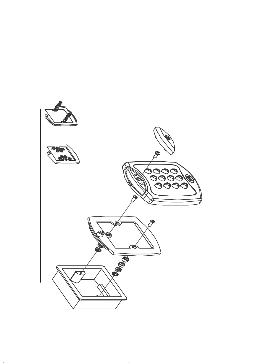
Security screw supplied with
the unit.
Place the Reader / Keypad onto the surface mount
collar and clip down into place.Use the security
screw supplied to attach the unit to the surfce mount
collar.
Mounting plate is attached to the pattress
box using the screws supplied. Ensure
the corect spacers have been used to
bridge the gap between the mounting
plate and the fixing wings of the pattress
box to avoid the mounting plate being
distorted.
Standard pattress
box.
Fig 2
Spacers break
away from main
component when
required by
installer for use.
Screws
Place the cap onto
the unit and push
firmly into place.
View showing
spacers stacking
Note:
Determine the distance between the pattress
box and the mounting plate, using the spacers
which are labelled 1mm to 4mm. This allows
the installer to make the required spacer length,
from 1mm to 10mm, by stacking spacers.
View showing mounting plate
before spacers are broken away.
3
ACT5prox Operating and Installation Instructions
10
Page 11

Mounting instructions for surface mount unit
Place the Reader / Keypad onto the
surface mount collar and clip down into
place.Use the security screw supplied to
attach the unit to the surfce mount colla
Fig 3
The surface mount collar is
mounted on the wall using
the fixing kit supplied in
the box.
Security screw supplied with
the unit.
Place the cap onto
the unit and push
firmly into place.
ACT5prox Operating and Installation Instructions
4
11
Page 12

User List
User User Name Card Number PIN Toggle
1
2
3
4
5
6
7
8
9
10
11
12
13
14
15
16
17
18
19
20
21
22
23
24
25
26
27
28
29
30
31
32
33
34
35
36
37
38
39
40
41
42
43
44
45
46
47
48
49
50
Tel: 353-1-4662570 Fax: 353-1-4520427 UK Locall: 0845 300 5204 Web: http://www.accesscontrol.ie E-mail: tech@accesscontrol.ie
Access Control Technology, Unit C1, South City Business Centre, Tallaght, Dublin 24, Ireland.
 Loading...