

Page 1
ASP116 EVOLUTION
The Lift control panel
USER MANUAL
FOR ELECTRIC LIFTS
V4.06
01-2012
v5.21
09-2018
Page 2

USER MANUAL « ASP 116 EVOLUTION »
Sprinte SAS, All rights reserved, including translation rights
2
Page 3

USER MANUAL « ASP 116 EVOLUTION »
Sprinte SAS, All rights reserved, including translation rights
3
CONTENTS
PRESENTATION ................................................................................................................................................................... 5
1.1 SAFETY INSTRUCTIONS ....................................................................................................................................................... 6
1.2 MECHANICAL CHARACTERISTICS .......................................................................................................................................... 6
1.3 ELECTRICAL CHARACTERISTICS ............................................................................................................................................. 6
1.4 CONTROL PANEL .............................................................................................................................................................. 7
1.5 WHAT’S NEW SINCE 5-20 SOFTWARE VERSION ...................................................................................................................... 8
1.5.1 New functions ..................................................................................................................................................... 8
1.5.2 Modifications ...................................................................................................................................................... 8
1.5.3 Corrections .......................................................................................................................................................... 9
2 SETUP THE LIFT EQUIPMENTS .................................................................................................................................... 10
2.1 MODIFYING A SETTING .................................................................................................................................................... 10
2.2 RELOADING FACTORY SETTINGS ......................................................................................................................................... 10
2.3 MYLIFT, APPLICATION FOR SMARTPHONE. ........................................................................................................................... 11
2.4 SETUP MENU ............................................................................................................................................................. 11
2.5 CONTROL PANEL CHARACTERISTICS .................................................................................................................................... 12
2.6 EQUIPMENT CHARACTERISTICS .......................................................................................................................................... 13
2.7 TEMPERATURE CONTROL ................................................................................................................................................. 15
2.8 POWER SUPPLY .............................................................................................................................................................. 16
2.9 IDENTIFICATION ............................................................................................................................................................. 16
2.10 HOIST MECHANISM ........................................................................................................................................................ 17
2.10.1 Electric lift ......................................................................................................................................................... 17
2.10.2 Standard configuration ..................................................................................................................................... 19
2.11 AUTOMATIC EVACUATION ................................................................................................................................................ 19
2.12 FREQUENCY INVERTER SETTINGS ........................................................................................................................................ 20
2.12.1 Lift information ................................................................................................................................................. 21
2.12.2 Motor characteristics ........................................................................................................................................ 23
2.12.3 Auto-tuning optimisation. ................................................................................................................................. 24
2.12.4 Encoder characteristics ..................................................................................................................................... 25
2.12.5 Speed loop optimisation .................................................................................................................................... 26
2.12.6 RollBack function for synchronous motors ........................................................................................................ 26
2.12.7 Brake management ........................................................................................................................................... 27
2.12.8 Asynchronous motors optimisation .................................................................................................................. 28
2.12.9 Inspection mode ................................................................................................................................................ 29
2.12.10 Electric noise reduction ................................................................................................................................. 29
2.13 BRAKE CONTROL ............................................................................................................................................................ 30
2.14 RE-LEVELLING OPERATION ................................................................................................................................................ 31
2.15 BUILDING ..................................................................................................................................................................... 32
2.16 USER OPERATION ........................................................................................................................................................... 34
2.17 FIRE OPERATION ............................................................................................................................................................ 36
2.18 VOICE SYNTHESIS ........................................................................................................................................................... 37
2.18.1 Voice synthesis in car ........................................................................................................................................ 37
2.18.2 Music in the car ................................................................................................................................................. 38
2.18.3 Voice synthesis on the car roof.......................................................................................................................... 39
2.18.4 Voice synthesis on floors ................................................................................................................................... 40
2.19 VISUAL INDICATIONS ....................................................................................................................................................... 41
2.19.1 Visual indications in car..................................................................................................................................... 41
2.19.2 Visual indications on floors ............................................................................................................................... 43
2.20 DOORS......................................................................................................................................................................... 45
2.21 CAR POSITIONING SYSTEMS .............................................................................................................................................. 49
2.21.1 Configuration of K04SP / K05SP ........................................................................................................................ 50
2.22 CAR LOAD CONTROLS ...................................................................................................................................................... 51
Page 4

USER MANUAL « ASP 116 EVOLUTION »
Sprinte SAS, All rights reserved, including translation rights
4
2.23 OVERSPEED MONITOR FOR MACHINEROOMLESS LIFTS. .......................................................................................................... 51
2.24 EMERGENCY TELEPHONES ................................................................................................................................................ 52
2.25 ENERGY SAVINGS ........................................................................................................................................................... 52
3 CONFIGURATION OF ELECTRONIC BOARDS « INPUTS / OUTPUTS » .......................................................................... 53
3.1 CAR AND FLOORS BUTTONS .............................................................................................................................................. 53
3.1.1 216SP................................................................................................................................................................. 53
3.1.2 217SP................................................................................................................................................................. 53
3.2 CONFIGURATION OF SPECIAL I/O OF 217SP ........................................................................................................................ 54
3.3 CONFIGURATION OF FLOOR INDICATION .............................................................................................................................. 54
3.4 CONFIGURATION I/O SUPERVISION .................................................................................................................................... 55
3.5 I/O CONFIGURATION OF THE BUS FLOORS (228SP, 137SP) ................................................................................................... 57
4 LIFT CONTROLLER MAINTENANCE ............................................................................................................................. 58
4.1 MAKE CALLS WITH THE CONTROLLER .................................................................................................................................. 58
4.2 TECHNICAL ASSISTANCE MENU .......................................................................................................................................... 58
4.3 DIAGNOSIS MENU .......................................................................................................................................................... 60
4.4 FAULTS LIST .................................................................................................................................................................. 61
4.4.1 Power supply ..................................................................................................................................................... 61
4.4.2 Lift ..................................................................................................................................................................... 62
4.4.3 Control panel ..................................................................................................................................................... 62
4.4.4 Car boards ......................................................................................................................................................... 64
4.4.5 Floor boards ...................................................................................................................................................... 64
4.4.6 Selection ............................................................................................................................................................ 66
4.4.7 K04SP/K05SP ..................................................................................................................................................... 67
4.4.8 Safety chain ....................................................................................................................................................... 67
4.4.9 Levelling ............................................................................................................................................................ 69
4.4.10 Movement ......................................................................................................................................................... 70
4.4.11 Doors ................................................................................................................................................................. 73
4.4.12 Overspeed ......................................................................................................................................................... 74
4.4.13 Temperature ..................................................................................................................................................... 74
4.4.14 Inverter .............................................................................................................................................................. 75
5 ELECTRONICS BOARDS .............................................................................................................................................. 78
5.1 ELECTRONICS BOARD IN MACHINERY .................................................................................................................................. 78
5.1.1 Lift controller boards « 216SP » ........................................................................................................................ 78
5.1.2 217SP expansion board ..................................................................................................................................... 81
5.1.3 214SP Power supply board ................................................................................................................................ 82
5.1.4 220SP motor interface board ............................................................................................................................ 83
5.1.5 225SP Expansion board 2 speeds motor ........................................................................................................... 84
5.1.6 212SP safety chain distribution board.............................................................................................................. 85
5.2 ELECTRONIC CARS IN INSPECTION BOX ................................................................................................................................ 86
5.2.1 211SP car controller board ................................................................................................................................ 86
5.2.2 210SP safety chain distribution board .............................................................................................................. 90
5.2.3 222SP power board for door second service ..................................................................................................... 92
5.2.4 223SP extension board for door second service ................................................................................................ 93
5.2.5 230SP Bluetooth board .................................................................................................................................... 94
5.3 LANDING ELECTRONICS BOARDS ........................................................................................................................................ 95
5.3.1 228SP landing board ......................................................................................................................................... 95
5.3.2 137SP landing board with voice synthesizer ..................................................................................................... 96
Document Reference :B-DP-10-006-09
Page 5
USER MANUAL « ASP 116 EVOLUTION »
Sprinte SAS, All rights reserved, including translation rights
5
Presentation
This manual is the reference document for installation and maintenance of your “ASP 116 evolution” control
panel. It explains in detail the configuration and diagnostic of your control panel.
This new range of control panels designed by Sprinte introduces the latest technology to meet lifts’ new
requirements. The “ASP 116 evolution” control panel is modular and particularly suited to modernising lifts.
Main functionalities:
- 32 floors
- CANopen LIFT compliant
Power control options:
- Variable frequency control 4 kw to 55 kw (Gear and Gearless)
- One or two speed control
- Speed until 1.6 m/s
- Optimization of energy consumption
Car positioning
- Magnetic reader with magnets on guide rails
- Optic fork (224SP)
- Absolute encoder with notched band (K04SP)
- Absolute reader with encoded stainless steel band./
Operation type:
- Universal travel, Up or Down Collective, Full Collective
- Up to quadruplex control
- Fire EN 81-73
- Inspection and emergency operation
- Key “reserved car”
- Overload detection
- Access codes with the car operating panel
- Two car operating panel
Door controls
- 2 doors
- Manual doors
- Fully automatic doors
- VVF doors (Nudging)
- Door open levelling
- Two doors with passing or selective mode
- Automatic and manual landing doors on the same face
Indicators
- Positions indicators (Dot matrix, LCD, TFT colour)
- Direction and next departure arrows
- Voice announcement of floor
Page 6
USER MANUAL « ASP 116 EVOLUTION »
Sprinte SAS, All rights reserved, including translation rights
6
Main advantages:
- Only one flat cable
- MP3 speech synthesizer
- Security chain pre-wired
- Configuration and application software saved on the SDCard
- 2 lines * 20 characters LCD display
- All defaults saved on the SD-CARD
- Time and date of the faults
- Control of Machine room temperature
- Voice assistance for the technical
1.1 Safety instructions
1) The control panel must be installed in a dry, clean room and only accessible to authorised staff.
2) The room temperature must not exceed 40° and must be greater than 0°
3) The lift must be taken out of service if the two-way communication system is not working
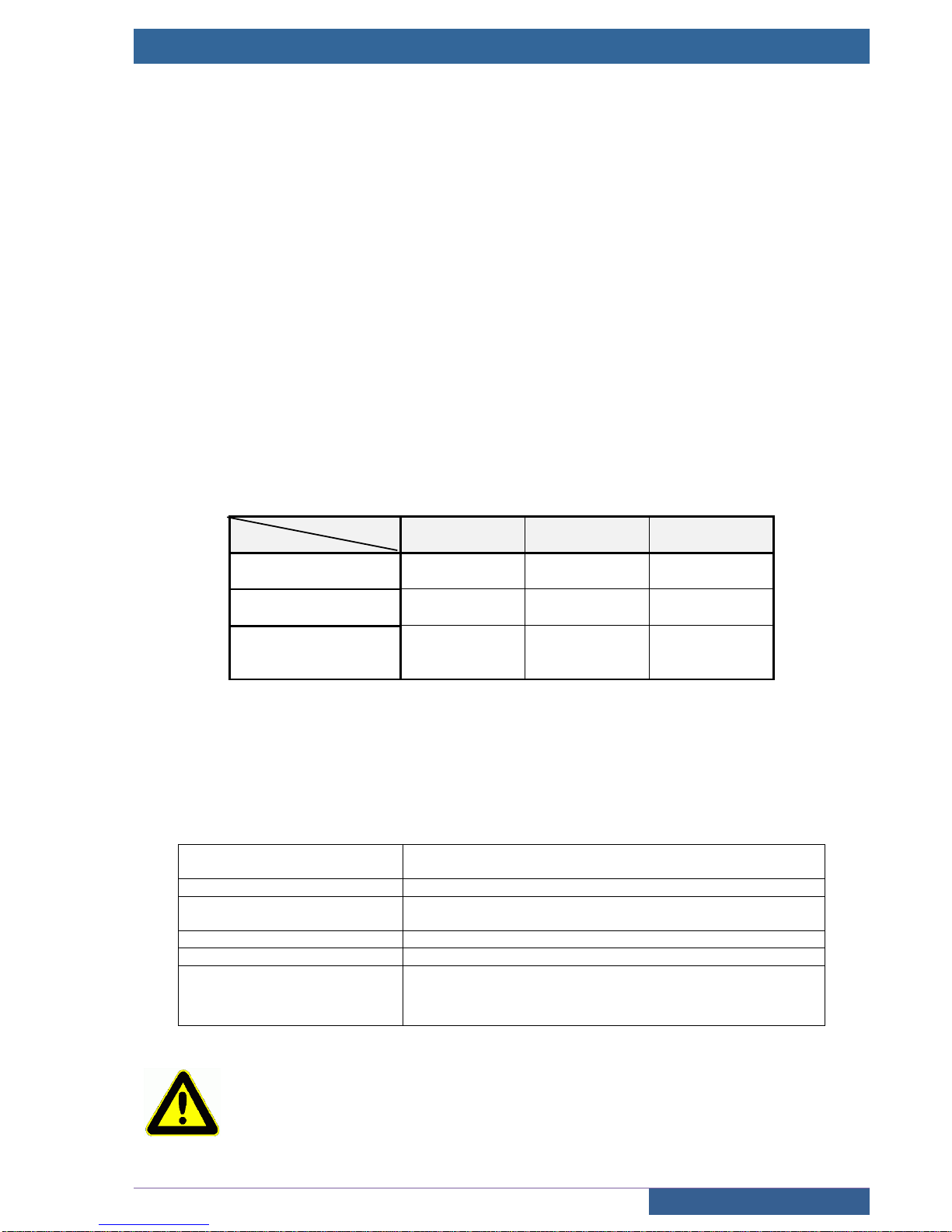
1.2 Mechanical characteristics
Cabinet size:
Power
Operation
4 to 11Kw
15 to 30Kw
37 to 55Kw
Frequency variation
800 x 600 x 300
1200 x 800 x 400
1600 x 900 x 400
Hydraulic control
800 x 600 x 200
800 x 600 x 200
800 x 600 x 200
Electric 1 and 2
speeds
800 x 600 x 200
800 x 600 x 200
800 x 600 x 200
The cabinet size can vary according to options
The control panel weight varies between 25Kg and 100Kg according to power
1.3 Electrical characteristics
The control panels are serial equipped with a protection system against lightning and all the contactors are
installed on Silentblocs in order to reduce noise emission outside the control panel
Working voltage
220Vac / 230Vac single phase or three phase, 380Vac /
400Vac three phase
Power consumption
70VA no load
Available voltage
24V full-wave 2A, 55V / 70V full-wave 4A, 110Vac / 1A, 220V
“220F” /2A
Safety chain voltage
110VAC
Emergency voltage
Battery 12V / 2,1Ah or 7,1 Ah
Call / Car buttons
Inputs / outputs single wire, earth return, voltage 24V
continuous
Type of indication (LED or light 24V / 50mA max)
This manual describes the functions of the software V04.06. It is possible that older versions of
software do not have all the features described. Check the version of the software before you
start reading the manual.
Page 7
USER MANUAL « ASP 116 EVOLUTION »
Sprinte SAS, All rights reserved, including translation rights
7
1.4 Control panel
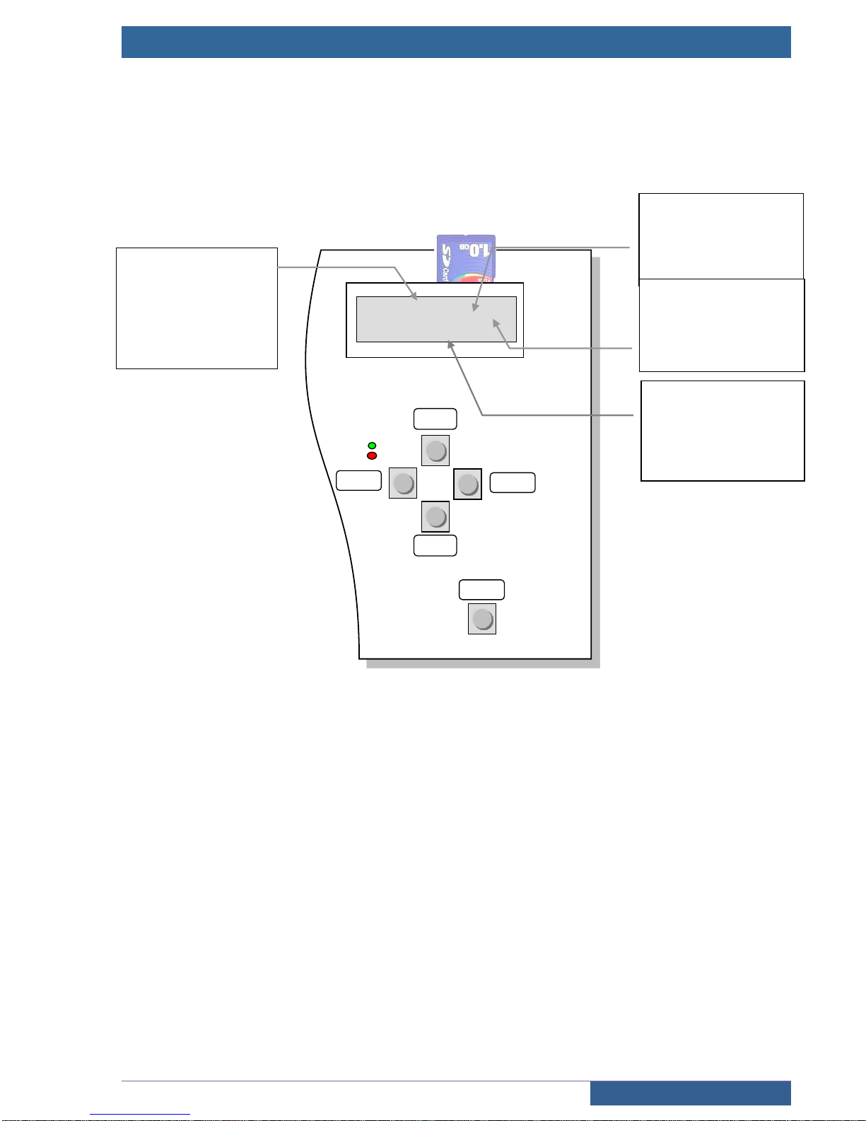
The control panel comprises an alphanumeric screen and navigation keypad equipped with five integrated
buttons. The control panel screen enables the lift’s status to be known at all times. The SDCard contains the lift’s
configuration and the lift’s software to enable restarting under the same conditions if the board is changed.
Contrast adjustment
Press and hold down the “BACK” key and press “ +” to increase contrast or “ -” to decrease it.
Navigating in the menus
Press the “ENTER” key on the keyboard to go into the lift’s configuration and diagnostics menu. Then press the
““ or ““ keys to navigate in the main menu. Push the “ENTER” key again to go into the desired submenu and
the “BACK” key to come back out of it.
+
Navigating in menu and selecting
the value of a configuration
option
-
Navigating in menu and selecting
the value of a configuration
option
BACK
Navigating in menu and
cancelling a configuration
modification
BAC
MODE
IN USE
EMERGENCY OPERA
INSPECTION
OUT OF USE
EMERGENCY
OUT OF POWER
LEVEL
A: AT LEVEL
U: UNDER LEVEL
O: OVER LEVEL
N: BETWEEN LEVELS
CURRENT ACTION
DOOR OPENING
CAR OVERLOAD
PRIORITY
…./…..
IN USE A0 D
AVAILABLE
RESET
BACK
ENTER
+
-
ENTER
Pushing the “ENTER” key
enables going back into
configuration and diagnostic
mode
RESET
Pushing this key for 4
seconds causes a control
panel RESET
“D” indicates there are
faults memorised
“D” flashes if a new
fault is recorded
Page 8

USER MANUAL « ASP 116 EVOLUTION »
Sprinte SAS, All rights reserved, including translation rights
8
1.5 What’s new since 5-20 software version
1.5.1 New functions
K05SP Car positioning system
This new car positioning system K05SP is an absolute linear shaft reader. Position is written on the encoded
stainless steel tape mounted from top to bottom of the shaft
The main assets of this reader :
1 mm precision.
very compact housing.
extremely simple assembly.
Sam shaft’s learning procedure as K04SP.
Very silent even at high speed
The choice of this reader appears in the following menu : CONFIGURATION ► CAR POSITION ►READER
Out of Use operation with doors opened
It’s now possible the car stands still with doors opened while the lift is in Out of Use operation,
It can be chosen in the following menu : CONFIGURATION ► BUILDING ► OOU.DOORS.OPENED
New floors indications selection
With 232 , 236 and 262 displays , the following indications have been added to the list :
0/1 , 1/2, 2/3 , 3/4 , 4/5 , 5/6, 6/7 , an 7/8
It can be chosen in the following menu : CONFIGURATION ► INDICATION ► FLOOR/DISPLAY.
Construction year
This parameter is only for informative purpose and shall be set to the construction year of the lift. This
construction year will be then displayed next to the CE mark on the load plate of the 236SP1 display.
If the year is set to 0, nothing will be displayed.
This setting can be found in the menu : CONFIGURATION ► IDENTIFICATION ► CONSTRUCT. YEAR
New supervision output "CALL °PENDING".
This output is activated as soon as an user request (car call or hall call) is currently pending or in progress ;the
output is reset as soon as there are not any user calls anymore or in case the lift is not in user mode.
It can be chosen in the following menu : CONFIGURATION ► I/O BOARDS ► 217SP► I/O REMOTE
Hoistway access detection
The hoistway access detection sets the lift out of order, in the case a landing door has been detected opened for
longer than 8 seconds (thanks to the landing doors safety locking contact), out of a normal car parking in user
mode. The presence of a technician is mandatory to set back the lift in user mode.
This detection only occurs in user mode
Caution : this detection can’t operate properly with a lift compliant to EN81-20 standard , as in that case the
landing doors are always unlocked when the lift is idle in user mode.
This detection can be enabled in the menu CONFIGURATION ► OPERATIONS ► HWAY.ACC.DETECT.
1.5.2 Modifications
Modification of the procedure after pit inspection
The procedure defined in the ASP116 EVOLUTION to put back the lift in service after exiting the pit inspection
mode, has been simplified. It is fully detailed in the installation (ref. B-DP-13-006 Annexe 2-5).
This procedure is valid only if the following parameter :
CONFIGURATION ► EQUIPEMENT ►REARM.INS.CUV. is set to [BY ASP116-EVO] (voir 2.6)
Door Bypass Device activation
The user mode is set of use as soon as the Door Bypass Device is activated .
Music in car
The playback of the music in car is stopped as soon as an emergency phone communication is detected. For
that, the 230SP board is needed, as the yellow/green indicators outputs of the phone are connected on this
board ; and the controller uses its states to detect the use of the emergency phone.
Page 9

USER MANUAL « ASP 116 EVOLUTION »
Sprinte SAS, All rights reserved, including translation rights
9
1.5.3 Corrections
In some rare cases, the « DIAL 211 BOARD » fault could be indefinetely detected, causing the lift to be
set out of use mode
In preparation for departure, and with the « maitainied closing » parameter set, a door for a service could
be reopened, because the door of the other service was already opened
In case of a software update form a version older than 4-06G to a version 5-12 or more, and with a
K04SP reader, the « DOOR AREA ON » fault was always detetced on the lowest floor.
In universal operation, the car could be « stuck » in preparation for departure » in the case a car call was
done during a levelling operation while the doors were closing.
The message « OCCUPIED » swithced off the 122SP display connected on the 216SP board, now the
display is unchanged.
A shaft light request from the pit inspection switched on the lights of all the shafts of the lift group.
In case of a main power supply failure, and with the « A3 CONTROL » parameter enabled, the « BRAKE
UNRELEASED » fault was always detected.
The max closing timer wasn’t used in case of nudging for the doors.
Page 10
USER MANUAL « ASP 116 EVOLUTION »
CONFIGURATION
Sprinte SAS, All rights reserved, including translation rights
10
2 Setup the lift equipments
The “SETUP” menu is used to adapt the control panel to your lift. It defines the lift’s system requirements as well
as the settings enabling the installation’s performance to be optimised.
All the control panels are delivered preconfigured according to the client’s datas.
The parameters with a start indication (example: « [PARAM]* ») are the default parameters
2.1 Modifying a setting
Modifying a setting is only authorised if the “PROTEC CONFIG” setting is set to “NOT PROTECTED”. If not a
message “MODIF NOT AUTH.” will appear.
To modify a setting, select it and press the “ENTER” key, the current value starts flashing. Pressing the “” or “”
keys changes its value. To validate your selection press the “ENTER” key again, the new value is saved and does
not flash. To cancel your modification press the “ESC” key.
Takes account of modifications
The modifications are not taking account while the lift is in use.
To save the modifications, press the “BACK” key several time to return to the main menu
The following message appears:
After 2 seconds, you can switch to the standard indication by pressing “BACK” key.
Take account of new settings
Wait until the lift is in an available state, ensure there is no-one remaining inside the car then
press the “RESET” key for two to three seconds. The lift restarts after initialisation with the new
settings.
2.2 Reloading factory settings
The configuration used by the control panel is saved in the DCF.txt file. Each setting modified by the console is
therefore saved in this file. In case of a problem loading the configuration or incorrect operation following a
configuration modification, you can go back to the factory settings. This configuration is backed-up in the EDS.txt
file.
To go back to the factory settings:
1) Press the “ +” button and the “ - “ button
2) Do a reset by keeping the “ +” and “ -“ buttons pressed down
3) Press the “ENTER“ key.
4) The lift control panel is configured with the factory settings
SAVE?
YES (+) NO (-)
Press “+” to confirm the modification or “-“ to cancel
If you pressed “+” the message “MODIFIED CONFIG” appears
FACTORY SETTINGS
CONFIRMATION OK>
Page 11
USER MANUAL « ASP 116 EVOLUTION »
CONFIGURATION
Sprinte SAS, All rights reserved, including translation rights
11
2.3 MyLift, application for smartphone.
“MyLift” application is a software for android-based devices designed to the lift’s owners and intended
to help them customize their lift this application gives access only to all of the user’s settings of the lift (voice
synthesizer, music, displays, access codes, date & time, etc...). Changes made with this application are taken
instantly in account by the controller, no need to reset it.
This application needs the second 230SP board, to give a separate bluetooth access from the first 230SP.
MyLift is available on
Google PlayStore
Every editable settings with Mylift , are identified
throughout this document by the logo of the application:
2.4 SETUP MENU
CONTROL PANEL
Protection of settings modification, selection of display language on the digital
console, date and time adjustment
EQUIPMENT
Control panel series type, consulting software version, number of expansion
boards
TEMPERATURE
Machinery temperature adjustment detection
POWER SUPPLY
Phase inversion
IDENTIFICATION
Name of client, address of lift, serial number, lift number in multiplex
HOIST
Hoist mechanism : Hydraulic systems, drive systems
RESCUE
Automatic evacuation of passengers in case of main power failure.
FREQ. INVERTER
Configuration of the inverter connected in CANbus with the 216SP controller
BRAKE
Brake configuration
LEVELLING
Levelling of the car with the doors opened
BUILDING
Number of levels, car stop level,..
OPERATIONS
type of operation, car light timer, car priority timer, car priority key
FIRE
Configuration of stricken floors, type of fire operation
VOICE SYNTHESIS
Voice synthesis configuration
INDICATORS
Configuration of type of displays landings and car with configuration of display
at each level. Type of arrow on landing and in car
DOORS
Type of doors, nudging, timers, CPC, SHOCK, opening/closing button, electro
cam, pre-opening.
CAR POSITION
Type of reader, recalibration, close levels, crossed flags
CAR LOAD
Overload ,complete
OVERSPEED
Settings for the overspeed monitor
ALARM
phone alarm configuration
ENERGY SAVINGS
Settings for the energy savings mode of the lift.
BOARDS I/O
Input-output settings for electronic boards of the controller
Page 12
USER MANUAL « ASP 116 EVOLUTION »
CONFIGURATION
Sprinte SAS, All rights reserved, including translation rights
12
2.5 Control panel characteristics
SETUP ► CONTROL PANEL
SETUP
Protection of settings modification
[PROTECTED]*
Consulting the configuration. No setting can be modified in this mode
[NOT PROTECTED]
Consulting and modifying the configuration
LANGUAGE
Choix de la langue d’affichage sur la console de l’armoire
[FRENCH]* [ENGLISH]
DATE
Date display
Date setting :
Press « ENTER » and press the arrows to change the day, the month and the year.
Press « ENTER » to validate the new date or « ESC » to cancel.
TIME
Time display
Time setting :
Press « ENTER » and press the arrows to change the hour, the minutes and the
second. Press « ENTER » to validate the new time or « ESC » to cancel.
NIGHT START
Display of start time for night schedule
The night range is used to reduce the sound volume of the vocal synthesis during the
night
Adjustment as for TIME setting
NIGHT END
Display of end time for night schedule
Adjustment as for TIME setting
Page 13
USER MANUAL « ASP 116 EVOLUTION »
CONFIGURATION
Sprinte SAS, All rights reserved, including translation rights
13
2.6 Equipment characteristics
CONFIGURATION ► EQUIPMENT
VERSIONS
Application version and electronic boards version of the equipment
[y.z]
POWER BOARD
Type of power board connected to the 216SP board
[NO BOARD], [220SP], [220SP+225SP]
PIT INSPECT. BOX
Presence of an inspection box in the pit.
If this box is present on your lift, you can plug it on 137SP board connected on the
landing CAN bus, or directly on 216SP main board
Be aware that in case of 137SP ,this board is not to be considered in the « LAND.
BOARDS NB » (see below in this table).
This 137SP board is fixed to ID #27, e.g. DIP1 DIP2 DIP4 and DIP5 set to ON, all
others set to OFF
[NO], [ON CN7/137SP], [ON PE3M/216SP]
PIT INSP.REARM.
Selection of the reset system after exiting pit inspection mode
This reset system may be fulfilled :
either by ASP116 Evolution
(procedure is fully detailed in the installation manual B-DP-13-006 Ann.2-5),
or by an external autonomous device
[BY ASP116-EVO], [BY EXT.SYSTEM]
PIT INSP.VOLUME
Volume adjustement of pit inspection box.
This setting is available only if the pit inspection box is managed by a 137SP board .
[0..7]
DBD
(Door Bypass device)
Presence of Door safety contacts bypass device.
This device is required by EN81-20 standard for maintenance of the doors’ contacts.
[NO], [YES]
217SP BOARDS NB
Number of 217SP boards
[0*..2]
223SP BOARDS NB
Number of 223SP boards
[0*..2]
LAND. BOARDS NB
Number of 228SP and 137SP boards on landing CanBus
[0*..25]
The boards are identified by the JT1 selector of the boards.
The identification is binary code:
DIP 1 = 1 if DIP1 is ON, DIP 2 = 2 if DIP2 is ON, DIP 3 = 4 if DIP3 is ON,
DIP 4 = 8 if DIP4 is ON, DIP 5 = 16 if DIP5 is ON,
Board = V _DIP1 + V_DIP2 * 2 + V_DIP3 * 4 + V_DIP4 * 8 + V_DIP5 * 16
Examples :
Board 0 : All the DIPs OFF
Board 10 : DIPs 2, 4 are ON
Board 23 : DIPs 1, 2, 3, 6 are ON
The “0 board” is the last on the bus (she has a tank circuit). The previous board is
numbered 1 and so on.
1 - 2
1 - 2
EXT 0
EXT 1
Page 14
USER MANUAL « ASP 116 EVOLUTION »
CONFIGURATION
Sprinte SAS, All rights reserved, including translation rights
14
230SP BOARDS NB
Number of 230SP boards
This board is used for Bluetooth communication and remote alarm LEDs
[0*..2]
BLUETOOTH PIN
Access code to the gateway 230SP n°0
This code secures bluetooth access to the lift control panel with EvoPAD application.
[XXXX]
CUST.BTOOTH PIN
Access code to the gateway 230SP n°1
This code secures bluetooth access to the lift control panel with the application
dedicated to the final customer (“MyLift” app., ...)
[1234] (default value)
MPLEX
Multiplex gateway
Using a gateway between the lift control panels to separate the floors CANbus
This parameter can’t be disabled if there is at least one board connected on the
landing bus (landing panel board ,pit inspection board , flexypage..).
[OUI] * [NON]
Page 15
USER MANUAL « ASP 116 EVOLUTION »
CONFIGURATION
Sprinte SAS, All rights reserved, including translation rights
15
2.7 Temperature control
SETUP ► TEMPERATURE
Chapter 0.4.16 of the standard EN81-20:2014: To ensure the correct functioning of the equipment in the well
and machinery space(s), i.e. taking into account the heat dissipated by the equipment, the ambient
temperature in the well and the machinery space(s) is assumed to be maintained between +5 °C and +40 °C.
Temperature control in the control panel
This security prohibiting lift operation if the temperature in the control panel exceeds the maximum tolerances
authorised by the electronic components.
MAX PANEL T°
Maximum temperature in control panel
If the temperature exceeds this threshold, the lift makes the passengers exit and
goes out of service until the temperature comes back down below the threshold
[20..70] °C (70°C by default)
MIN PANEL T°
Minimum temperature in control panel
If the temperature goes below this threshold, the lift makes the passengers exit and
goes out of service until the temperature goes back up above the threshold
[-10..15] °C ( 0°C by default)
Temperature control in machine room
Security prohibiting lift operation if the temperature in the machine room exceeds the maximum tolerances
authorised by the standard.
MACHINE ROOM T°
Activation of the temperature controls in the machine room
Le control sis done by a 132SP temperature captor that it is connected to the MC2M
connector of the 216SP board.
[YES]* [NO]
MAX MACHINE T°
Maximum temperature in machine room
If the temperature exceeds this threshold, the lift makes the passengers exit and
goes out of service until the temperature comes back down below the threshold
[20..60] °C (40°C by default)
MIN MACHINE T°
Minimum temperature in machine room
If the temperature exceeds this threshold, the lift makes the passengers exit and
goes out of service until the temperature comes back down below the threshold
[-10..15] °C ( 0°C by default
)
HEATING
Switching on heating if temperature is lower than the threshold
Output CN6I-CHAUF / 220SP is activated
[-10..18] °C ( 5°C by default)
VENTILATION
Switching on ventilation if temperature is greater than threshold
Output CN6I-VENT / 220SP is activated
[22..60] °C ( 30°C by default)
Page 16
USER MANUAL « ASP 116 EVOLUTION »
CONFIGURATION
Sprinte SAS, All rights reserved, including translation rights
16
2.8 Power supply
SETUP ► POWER SUPPLY
PHASE CONTROL
Detection of phase inversion or failure
[NO DETECTION] [DETECTION]*
2.9 Identification
CONFIGURATION ► IDENTIFICATION
CLIENT
Name of client
Name of company
[16 characters]
REFERENCE
Reference name
Lift address where control panel is installed
[16 characters]
SERIAL NUMBER
Control panel serial number
[YYMMXXX] YY : Year of manufacture MM : Month of manufacture
XXX : Number in the month
SIMPLEX NUMBER
Multiplex lift number
[1*..4] In multiplex each lift must have a separate number
LIFT MARK
Serial lift number displayed in car
N° [16 characters]
CE MARK
CE mark displayed in car
[XXXX]
CONSTRUCT.YEAR
Construction year of the lift
This construction year will be displayed next to the CE mark on the load plate of the
236SP1 display.If the year is set to 0, nothing will be displayed.
[XXXX]
Page 17
USER MANUAL « ASP 116 EVOLUTION »
CONFIGURATION
Sprinte SAS, All rights reserved, including translation rights
17
2.10 Hoist mechanism
SETUP ► HOIST
HOIST TYPE
Type de traction
[ELECTRIC VVF] [HYDRAULIC] [ELECTRIC 1V] [ELECTRIC 2V]
2.10.1 Electric lift
INVERTER
Type of frequency inverter
[ADL300 M-SPEED] [Z.A. ZETADYN] [ALTIVAR ATV71L] [ATV71L BUS]
INSPECTION SPEED
Selection of movement speed during inspection
[LOW SPEED]* [HIGH SPEED]
TRACTION TYPE
Traction type
[POSITIV DRV LIFT] [FRICTION LIFT] [GEARLESS MOTOR]
RELEASE LINE
Timing delay of the release of line contactors
Adjustment of time limit to release the line contactors , see control timing chart next
page
[0.4..4] seconds (1,5 s by default)
ROPE WEAR
Monitoring of the wear of plastic sheathed ropes
The plastic sheathed ropes have to be replaced after a maximum number of direction
changes of the car (see below to adjust this number).
You have to activate this function if your lift is equipped with these ropes
[NO]* [YES]
MAX NB (ROPE)
Maximum number of direction changes (for rope wear).
Ask the ropes supplier to set the correct value.
Every direction changes of the car is counted to monitor the wear of plastic sheathed
ropes..
Once the maximum value set here is reached, the Lift falls out of order and you have
to replace the ropes. A warning is reported at 95% of this max value (see §4.4.10).
The current value of the counter is visible in the DIAGNOSIS->STATISTICS menu
(cf§4.3). When ropes have been replaced, reset this value to 0.
[0..9.999.999]
Inspection speed must not exceed 0.63 m/sec
Page 18
USER MANUAL « ASP 116 EVOLUTION »
CONFIGURATION
Sprinte SAS, All rights reserved, including translation rights
18
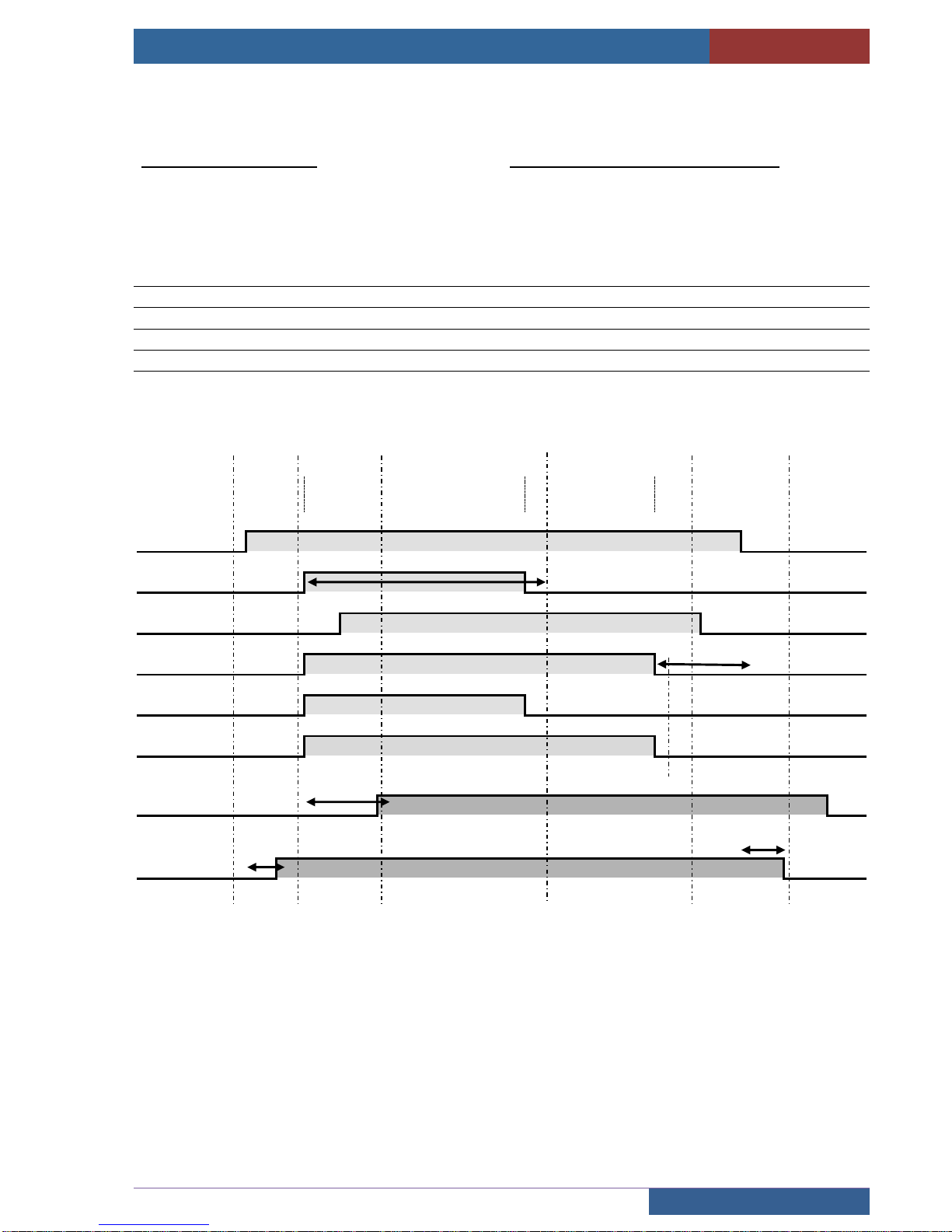
Inverter command timing diagram
Control panel commands
LA, LB : Line contactors
UC : Up command
DC : Down command
HS : High speed command
LS : Low speed command
BRAKE : The brake is driven by the inverter
Signals controlled by the control panel
MR Motor rotation
CC Contactor control
T1 If CC not active at end of 2 seconds: Contactors sticking fault
T2 If RM not active at end of 4 seconds: RM fault
T3 Adjustable brake spring time, release of LA, LB at end of time
T4 If CC not active at end of 2 seconds: Fault contactors sticking
T5 Brake boost time on starting
High speed
deceleration
stop
LA/ LB
BOOST BRAKE
BRAKE
UC or DC
HS
LS or INSP
MR
CC
T2
T3
T1
T5
T4
Page 19
USER MANUAL « ASP 116 EVOLUTION »
CONFIGURATION
Sprinte SAS, All rights reserved, including translation rights
19
2.10.2 Standard configuration
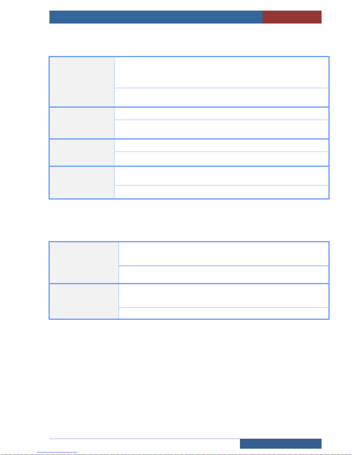
NO CAR MOVEMENT
Timing to detect a no movement of the car
Maximum car movement time without having information from position reader. Once
time is passed, the lift is faulty.
This security is deactivated in INSPECTION mode and LEVELLING mode
224SP : [10..20] seconds (20 sec by default)
K04SP/K05SP : [01..05] seconds (5 sec by default)
MAX ACCELER.
maximum authorized acceleration of the car measured by K04SP / K05SP
[0..2,5] m.s2 (2,5 sec by default)
« 0 » value disables the function
MAX LS TIMING
Maximum low speed movement lift in normal service
[10..20] seconds (20 s by default)
THERMAL PROTECT
Type of thermal protection of the traction machine
Use the input CN12I-ST / 220SP
[NO PROBE] [RESISTIVE PROBE] [DRY CONTACT]*
2.11 Automatic evacuation
CONFIGURATION ► RESCUE (only available with ATV 71L BUS inverter type )
RESCUE
Automatic evacuation of passengers in case of main power failure.
In this case, the ATV71L BUS inverter is able to move the car to the nearest floor,
choosing the easiest direction.
[NO] : Rescue off
[BY RELAY]: Rescue is launched by a timer relay.
RESCUE SPEED
Car speed in evacuation operation
This setting is transmitted to the inverter when moving in evacuation operation.
Unit is in Hertz
[0,1..5,0] hz
Page 20
USER MANUAL « ASP 116 EVOLUTION »
CONFIGURATION
Sprinte SAS, All rights reserved, including translation rights
20
2.12 Frequency inverter settings
CONFIGURATION ► FREQ. INVERTER
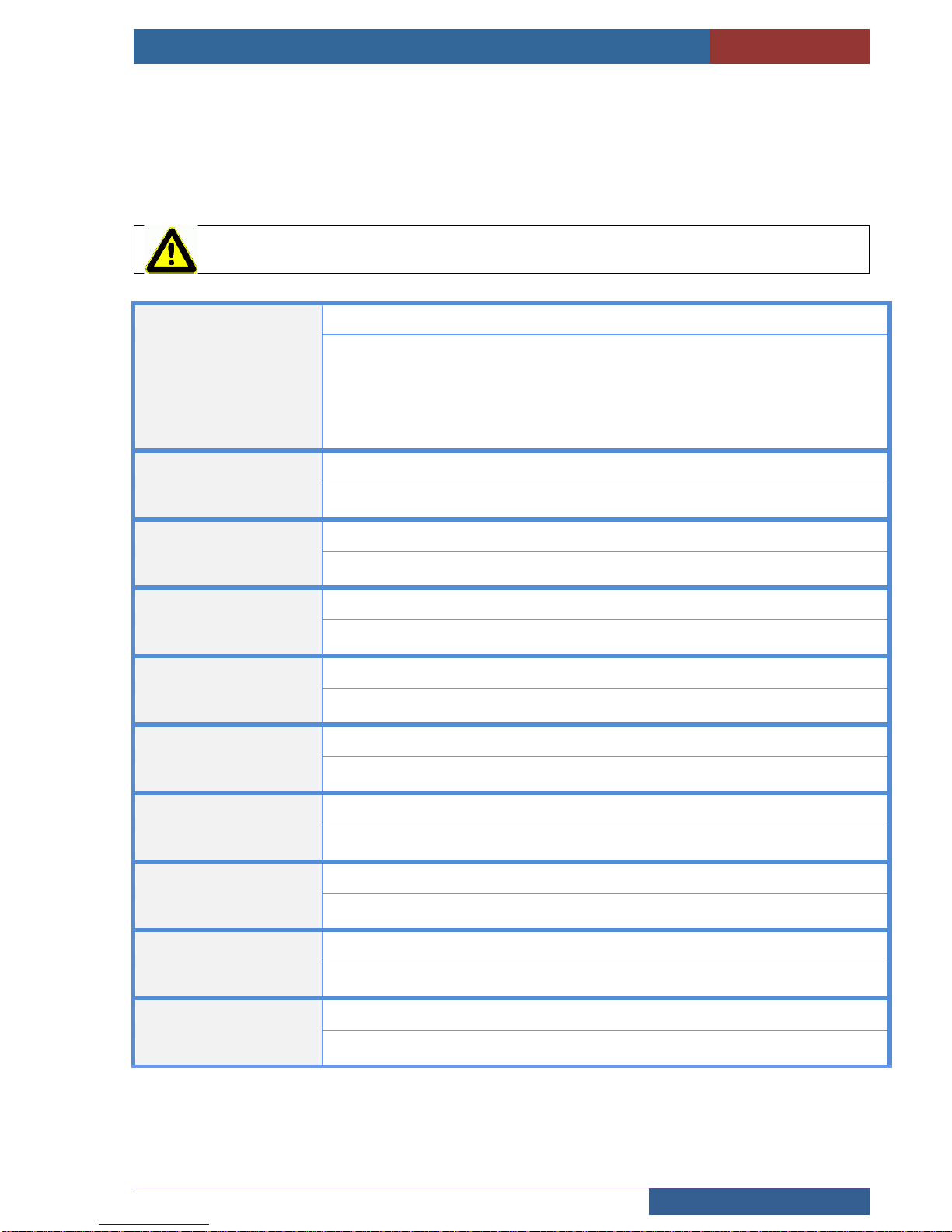
Some information like speed, motor current, output frequency, power supply of the inverter are available in this
menu :
DIAGNOSTIC ► INVERTER
Warning, to modify the parameters of the inverter, it is necessary to have :
PROTECT. MENU VF = NON PROTEGE
MENU VF PROTECT.
Protection du menu variateur
[PROTECTED]*
In this mode, you only can read the inverter configuration. The parameter goes
automatically in PROTECTED mode at midnight to avoid wrong manipulation.
[NO PROTECTED]
Put the parameter to «NO PROTECTED” to be authorized to modified the inverter
parameters
LIFT DATAS
Information of the lift
Press « ENTER » to go in the menu
MOTOR DATAS
characteristics of the motor
Press « ENTER » to go in the menu
ENCODER DATAS
characteristics of the encoder
Press « ENTER » to go in the menu
SPEED LOOP
Speed loop optimisation
Press « ENTER » to go in the menu
ROLLBACK
Rollback management
Press « ENTER » to go in the menu
BRAKE
Adjustment of the starting to stopping of the brake
Press « ENTER » to go in the menu
ASYNC. OPTIMIZ.
Asynchronous motors optimisation
Press « ENTER » to go in the menu
INSPECTION MODE
inspection mode parameters
Press « ENTER » to go in the menu
NOISE LEVEL
Noise reduction
Press « ENTER » to go in the menu
Page 21
USER MANUAL « ASP 116 EVOLUTION »
CONFIGURATION
Sprinte SAS, All rights reserved, including translation rights
21
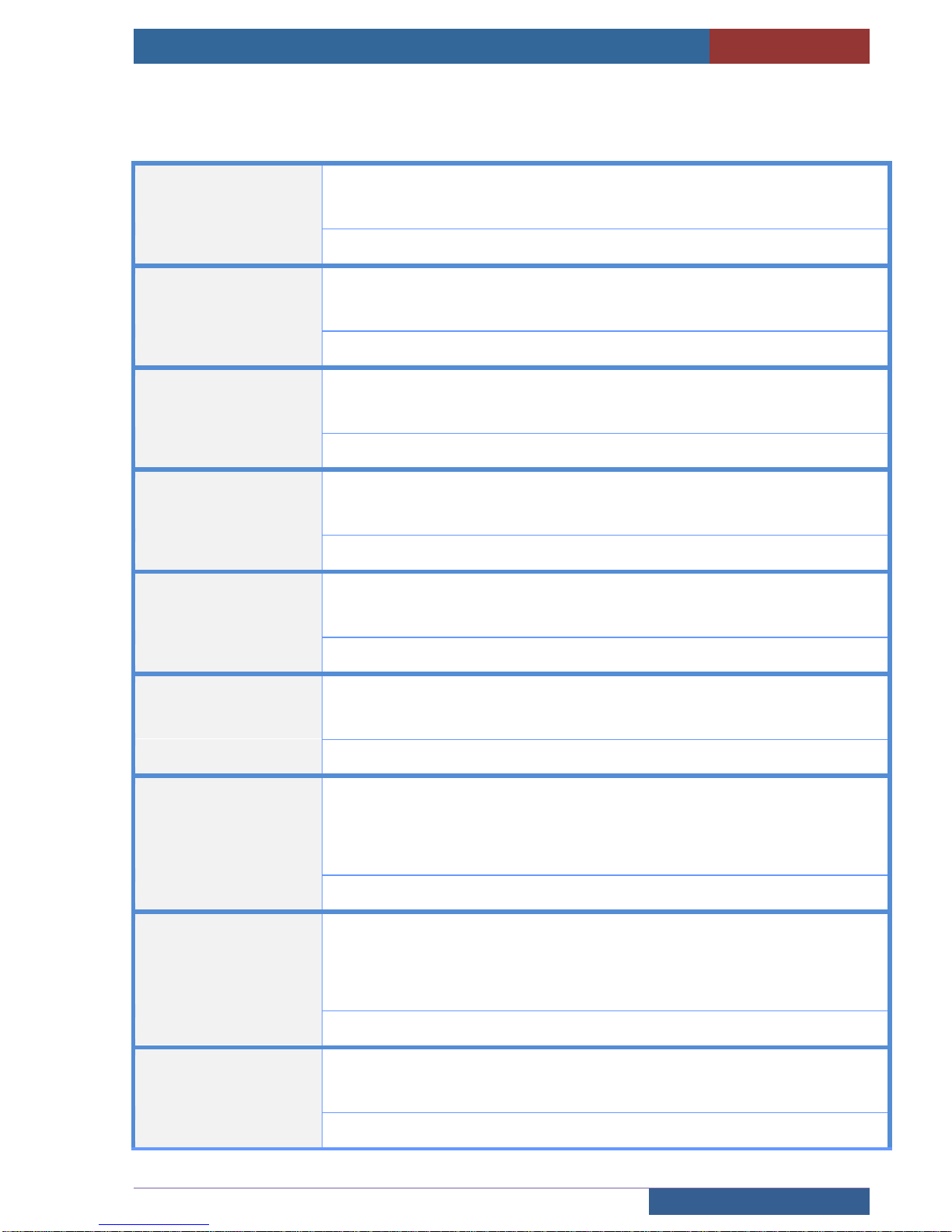
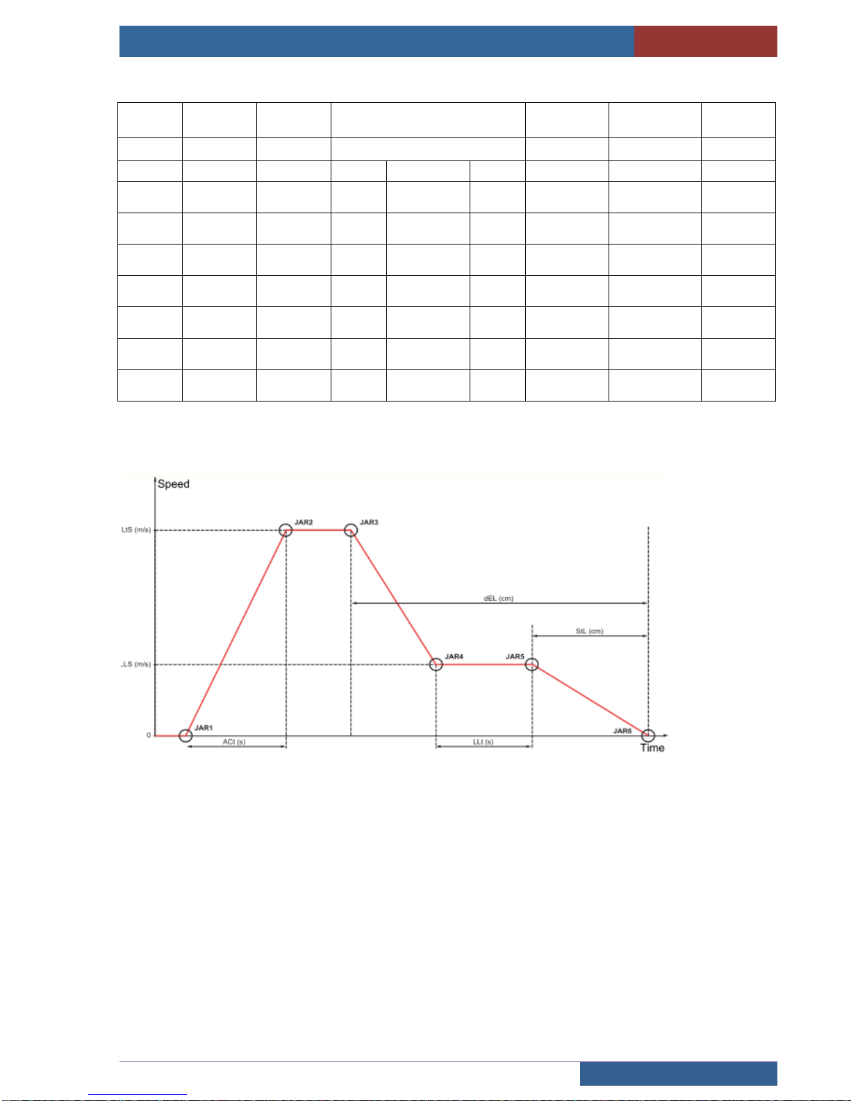
2.12.1 Lift information
CONFIGURATION ► FREQ. INVERTER ► LIFT DATAS
CAR RATED SPEED
Car rated speed at nominal motor frequency (CSP)
The car rated speed corresponds to the linear speed of the lift car when the motor
runs at its rated speed.
[0,1..5] m/s
LIFT CAPACITY
Capacity of the lift (LCA)
The payload corresponds to the maximum permissible load in the lift car. It must
always be stated in the lift car (for example: 630 kg - 8 persons)
[0..48000] kg
ACCEL. COMFORT
Acceleration comfort (ACM).
This parameter defines the maximal acceleration and deceleration authorized during
the movements of the lift.
[0,1..2] m/s2 par défaut 0,8 m/s2
LIFT TOP SPEED
Lift top speed (LtS).
The travel speed corresponds to the linear speed of the car in steady state (high
speed).
[0,1..1,6] m/s
ACCELER. TIME
Acceleration time (ACt)
The acceleration time corresponds to the time the car will take to attain its “Lift top
speed”
[0,5..60] seconds
STOP LENGHT
Stop length (StL)
The stop length corresponds to the distance separating the stop indicator from the
step the car is destined to reach.
[1 à 60] cm
LEVELING SPEED
Lift leveling speed (LLS).
The lift leveling speed is calculated by the drive automatically. If the calculated speed
is not suitable (because it corresponds to a mechanical resonance frequency for
example), it can be re-entered manually. In this case, the lift leveling time should be
recalculated.
[0,01 à 0,50] m/s
LEVELING TIME
Lift leveling time (LLt)
The lift leveling time corresponds to the time the car will spend at lift leveling speed in
steady state.If the lift leveling time is too short, the ride will be uncomfortable (rolling
sensation).If the lift leveling time is too long, the ramp between LtS and LLS will be
intense (loss of comfort).
[0,50 à 10,00] sec
DECELER LENGHT
Deceleration length (dEL)
The slowdown length corresponds to the distance separating the slowdown indicator
from the floor the car is destined to reach.
[10,0 à 999,9] cm
Page 22
USER MANUAL « ASP 116 EVOLUTION »
CONFIGURATION
Sprinte SAS, All rights reserved, including translation rights
22
Recommended parameters:
Car rated
speed
Acceleration
comfort
acceleration
time
Deceleration lenght
Leveling
speed
Levelling
time
Deceleration
lenght
LtS
ACM
Act
dEL (cm)
LLS
LLt
StL
(m/s)
m/s2
Sec.
mini.
Standard
max.
m/s
sec
cm
0.40
0,8
4
70
80
100
0,08
2
2,5
0.60
0,8
4
100
110
130
0,08
2
2,5
0.80
0,8
4
115
130
165
0,08
2
2,5
1.00
0,8
4
130
150
200
0,08
2
2,5
1.20
0,8
4
150
180
230
0,08
2
2,5
1.40
0,8
4
180
210
260
0,08
2
2,5
1.60
0,8
4
200
230
300
0,08
2
2,5
Page 23
USER MANUAL « ASP 116 EVOLUTION »
CONFIGURATION
Sprinte SAS, All rights reserved, including translation rights
23
2.12.2 Motor characteristics
CONFIGURATION ► FREQ. INVERTER ► MOTOR DATAS
AUTO TUNING
Auto-tuning (tUn) of the motor
It is essential that all the motor parameters are correctly configured before starting
auto-tuning.
[NO] Auto-tuning not performed.
[YES] Auto-tuning is performed as soon as possible, go to « emergency
operation » mode and push the going up button of the «emergency box.
[DONE] auto-tuning was performed
MACHINE TYPE
Machine type
[STANDARD]*
The lift is equipped with a standard motor
[GEARLESS SPRINTE]
The lift is equipped with a Sprinte Gearless machine
GEARLESS TYPE
Gearless reference type
[NOT REFERENCED] [103 02.1/2.3KW] [103 02.1/4.6KW] [103 02.3/3.4KW]
[103 02.3/6.7KW] [103 02.3/11.7KW] [103 04/6.61KW] [103 04/10.6KW]
[103 04/13.22KW] [103 05/4.3KW] [103 05/8.6KW] [103 05.2/5.225KW]
[103 05.2/10.45KW] [103 05.2/18.29KW] [MCG150 7KW]
CONTROL TYPE
Motor control type (Ctt)
[SYNC.CL] (FSY) Closed-loop synchronous motor. For permanent magnet
synchronous motors with sinusoidal electromotive force (EMF) only, with
encoder.
[ASYNC CL] (FVC) Closed-loop current flux vector control for motor with encoder.
[ASYNC OL] (SVC U) Open-loop voltage flux vector control with automatic slip
compensation according to the load.
[PROD TEST] Only used for production tests,never use it on a real lift
RATED SPEED
Rated motor speed given on the nameplate. (nSP or nSPS)
[0..60000] Tr/min
RATED POWER
Rated motor power given on the nameplate (nPr)
[0 à 80] kW
RATED VOLTAGE
Rated motor voltage given on the nameplate. (UnS)
[100 à 480] V
RATED CURRENT
Rated motor current given on the nameplate. (nCrS ou nCr)
[0,1 ..200] A
THERM. CURRENT
Motor thermal protection current (ItH)
To be set to the rated current indicated on the motor nameplate
[0,1 à 200] A ( 150% of In motor)
CURRENT LIMIT
Used to limit the motor current. (CLI)
[0,1 à 200] A ( 150% of In motor)
Page 24
USER MANUAL « ASP 116 EVOLUTION »
CONFIGURATION
Sprinte SAS, All rights reserved, including translation rights
24
PHASE ROTATION
Phase Rotation (PHr)
This parameter can be used to reverse the direction of rotation of the motor without
reversing the wiring.
[ABC] [ACB]
Asynchronous motor parameters:
RATED FREQUENCY
Rated motor frequency given on the nameplate. (FrS)
[10..1600] Hz
Synchronous motor parameters:
MOTOR TORQUE
Rated motor torque given on the nameplate. (tqS)
[1..65535] Nm
POLES PAIRS
Number of pairs of poles on the synchronous motor. (PPns)
[1 .. 50]
2.12.3 Auto-tuning optimisation.
ASYNCHRONOUS MOTORS
- For asynchronous motors the auto-tune should always be run in open loop. Only switch to closed loop once
this is finished.
- For old asynchronous motors with a high slip:
1) Configure the speed to 1380rpm instead of 1500rpm displayed on the motor
2) Calculate the power and enter it into the auto-tune.
P = mot. voltage X nom. motor intensity X √3 X cosφ
1CV = 736 W
SYNCHRONOUS MOTORS
- Formula for calculating the number of motor pole pairs:
Pole pairs = Motor Frequency (Hz) X 60
Motor Speed (rpm)
- Formula for calculating the motor couple:
Motor couple (Nm) = Motor power (Kw) X 9549
Max. pulley rotation (rpm)
Page 25
USER MANUAL « ASP 116 EVOLUTION »
CONFIGURATION
Sprinte SAS, All rights reserved, including translation rights
25
2.12.4 Encoder characteristics
CONFIGURATION ► FREQ. INVERTER ► ENCODER DATAS
ENCODER TYPE
Type of encoder used. (UECP)
[UNDEFINED] [ENDATSINCOS] [SSI] [SINCOS] [HIPERFACE] [ENDAT 2.1]
(by default ENDATSINCOS for synchronous machines)
SUPPLY VOLTAGE
Rated voltage of encoder used. (UECU)
[UNDEFINED] [5 V] [8 V] [12 V] (by default 5V for ASYNC)
RESOLUTION
Number of lines (UELC) or number of pulses per encoder revolution. (PGI)
[1..10000] (par défaut : 2048 en SYNC et 1024 en ASYNC)
FILTER
Activation of encoder feedback filter (FFA)
[NO] [YES]*
FILTER VALUE
Encoder filter value (FFr)
Encoder feedback filter time constant in milliseconds.
[0..50] ms (par défaut : 10 ms en SYNC et 20 ms en ASYNC)
REVERSE ROTATION
Activates reverse of encoder rotation. (EnrI)
In some assemblies, the encoder positive direction of rotation is reversed in relation
to the motor direction. When this is the case, this parameter needs to be activated in
order for the motor and the encoder both to have a positive direction of rotation.
[NO] * [YES]
Page 26
USER MANUAL « ASP 116 EVOLUTION »
CONFIGURATION
Sprinte SAS, All rights reserved, including translation rights
26
2.12.5 Speed loop optimisation
CONFIGURATION ► FREQ. INVERTER ► SPEED LOOP
LOOP GAIN
Frequency loop gain (FLG)
Used to adapt the pace of the machine speed transients according to the dynamics.
For machines with high resistive torque, high inertia or fast cycles, increase the gain
gradually.
Vibrations may occur if there is too much gain. If there is no access to the gain, there
may be a difference between the chosen speed and the actual car speed.
[0 .. 100] %
LOOP STAB
Loop stability (StA)
Used to adapt the return to steady state after a speed transient, according to the
dynamics of the machine. Gradually increase the stability to increase control loop
attenuation and thus reduce any overspeed.
[0 .. 100] %
REJECTOR FILTER
Notch Filter Activation (nFA)
This parameter activates the notch filter function. 2 independent notch filters can be
configured.
This parameter can’t be modified without our after sale service support.
[NO] [FIRST] [SECOND] [ALL]
2.12.6 RollBack function for synchronous motors
CONFIGURATION ► FREQ. INVERTER ► ROLLBACK
ROLLBACK MGT
Activation of Rollback management function (rbM)
[NO] [YES]
ROLLBACK COMP.
Rollback compensation gain. (rbC)
[0..1000] % (by default 20 %)
ROLLBACK DAMPING
Rollback coefficient damping. (rbd)
[0..1000] % (by default 50 %)
RIGIDITY CTRL
Activation of start-up stiffness boost function. (SUSb)
This function is compliant with the rollback management function Rollback . It is
recommended to activate both.
The Start-up stiffness boost adapts the IBR current level according to the encoder
feedback while the brake is opening.
[NO] [YES]
Page 27
USER MANUAL « ASP 116 EVOLUTION »
CONFIGURATION
Sprinte SAS, All rights reserved, including translation rights
27
2.12.7 Brake management
CONFIGURATION ► FREQ. INVERTER ► BRAKE
STARTUP ADJUST
Startup adjustment of the brake
Press « ENTER » to go in the menu
STOP ADJUST
Stopping adjustment of the brake
Press « ENTER » to go in the menu
CONFIGURATION ► FREQ. INVERTER ► BRAKE► STARTUP ADJUST
RELEASE TIME
Brake release time delay (brt)
[0.. 5] seconds (1 sec by default)
RELEASE FREQ.
Brake release frequency threshold (bIr)
Only in ASYNC OL
[0,0.. 10,0] Hertz (0,1 Hertz by default)
RELEASE CURRENT
Brake release current ( Ibr)
Brake release current threshold for Ascending or Forward movement.
[-100.. 100] Amperes (-0,1A by default for SYNC 0 A for ASYNC)
CONFIGURATION ► FREQ. INVERTER ► BRAKE ► STOP ADJUST
ENGAGE FREQ.
Brake engage frequency threshold (bEn)
Only in ASYNC OL
[0,0.. 10,0] Hertz
ENGAGE DELAY
Brake engage delay (tbE)
Time delay before request to engage brake. To delay brake engagement, if you wish
the brake to be engaged when the drive comes to a complete stop.
[0,00..5,00] seconds
ENGAGE TIME
Brake engage time (bEt)
[0,00..5,00] seconds
Page 28
USER MANUAL « ASP 116 EVOLUTION »
CONFIGURATION
Sprinte SAS, All rights reserved, including translation rights
28
2.12.8 Asynchronous motors optimisation
CONFIGURATION ► FREQ. INVERTER ► ASYNC. OPTIMIZ.
SLIP
Slip compensation
Press « ENTER » to go in the menu
BOOST
Réglage du courant magnétisant du moteur à basse vitesse
Press « ENTER » to go in the menu
2.12.8.1 Slip compensation
CONFIGURATION ► FREQ. INVERTER ► ASYNC. OPTIMIZ. ► SLIP
This parameter can increase the stop precision and the comfort of the travelling
SLIP COMPENSATION
Slip compensation (SLP)
Adjusts the slip compensation around the value set by the rated motor speed.
The speeds given on motor nameplates are not necessarily exact.
• If slip setting < actual slip: the motor is not rotating at the correct speed in steady
state, but at a speed lower than the reference.
• If slip setting > actual slip: The motor is overcompensated and the speed is
unstable.
[0.. 100] %
Page 29
USER MANUAL « ASP 116 EVOLUTION »
CONFIGURATION
Sprinte SAS, All rights reserved, including translation rights
29
2.12.8.2 Boost managment
CONFIGURATION ► FREQ. INVERTER ► ASYNC. OPTIMIZ. ► BOOST
BOOST
Boost (bOO)
Adjustment of the motor magnetizing current at low speed, as a % of the rated
magnetizing current. This parameter is used to increase or reduce the time taken to
establish the torque. It allows gradual adjustment up to the frequency set by “Action
Boost”.
[0.. 100] %
ACTION BOOST
Action Boost (FAb)
Frequency above which the magnetizing current is no longer affected by BOOST
[0 à 500] Hz
2.12.9 Inspection mode
CONFIGURATION ► FREQ. INVERTER ► INSPECTION MODE
INSPECTION SPEED
Value of the "inspection" mode frequency reference. (ISRF)
[0..25,0] Hz
ACCELERATION
Time to accelerate (ACC)
Time to accelerate from 0 to the inspection speed.
Make sure that this value is compatible with the inertia being driven.
[0..10] seconds
2.12.10 Electric noise reduction
CONFIGURATION ► FREQ. INVERTER ► NOISE LEVEL
SWITCHING FREQ.
Switching freq.
Switching frequency setting.
[0..16] KHz (8 KHz by default)
NOISE REDUCTION
Noise reduction (nrd)
Random frequency modulation prevents any resonance, which may occur at a fixed
frequency.
[NO]* [YES]
Page 30

USER MANUAL « ASP 116 EVOLUTION »
CONFIGURATION
Sprinte SAS, All rights reserved, including translation rights
30
2.13 Brake control
SETUP ► BRAKE
A3 CONTROL
Brake control in conformance with chap.5.6.7.3 of EN81-20
This control is only possible with a synchronous motor and a ATV LIFT inverter driven
with CANbus.
If this parameter is activated :
The brake control use automatically the 2 brakes inputs
The ATV LIFT inverter controls the brake position in same time as the
lift controller.
Control of the brake “1” on the input CN13-I CFR1 / 220SP
Control of the brake “2” on the input CN13-I CFR2 / 220SP
To change the type of dry contact :
CONFIGURATION ► BOARDS I/O ► 216SP BOARD ► 220SP ► {NC /NO}
[NO] [YES]
BRAKE BOOST
Current brake BOOST during the starting phase
The option sends more current to the brake coil on starting to help release the motor
(Also usable for gear brakes).
Use the output CN6I-BOOST / 220SP
[NO] [YES]
BRAKE BOOST TIME
Duration of the brake « boost »
(see timing chart VF control page 18)
[0,5..5] seconds
BRAKE POSITION
Control of the brake position
Detection of the brake position on the 220SP board
If the brake isn’t released, la door isn’t opened and the lift is out of order
Control of the brake “1” on the input CN13-I CFR1 / 220SP
Control of the brake “2” on the input CN13-I CFR2 / 220SP
To change the type of dry contact :
CONFIGURATION ► BOARDS I/O ► 216SP BOARD ► 220SP ► {NC /NO}
[OFF] [CTRL 1 BRAKE] [CTRL 2 BRAKES]
Page 31
USER MANUAL « ASP 116 EVOLUTION »
CONFIGURATION
Sprinte SAS, All rights reserved, including translation rights
31
2.14 Re-levelling operation
SETUP ► LEVELLING
LEVELLING
LEVELLING OPERATION
Maintaining the car at landing level with doors open. This function is deactivated in call
or inspection mode . Connector CB10 / 211SP
[NO]
No levelling is done if the car drifts in door area. Only forced closing of doors if the car
exits the door area
[YES]
In case of drift while parking, the car is re-levelled with doors opened thanks to
activation of security relay. Movement is done at low speed with spring cam.
LEVELLING TIME
Maximum levelling time
This is the maximum time to regain level in case of car backstop. If the car has not
regained its level within this time, a fault “LEV. TOO LONG” is given.
[05..30] seconds
LEVELLING CT
Levelling counter
A limited number of levellings is authorised on the landing. A fault “LEV REPEATED” is
activated if the threshold is exceeded.
[5..15]
LEVELLING TPO
Maintaining time of levelling.
Once the floor is reached, the levelling movement is maintained during the value of this
temporization. With a very accurate motor (no slip), the car could stop beneath the
floor. This can be solved with this parameter
[5..15] seconds (0s default value)
Page 32
USER MANUAL « ASP 116 EVOLUTION »
CONFIGURATION
Sprinte SAS, All rights reserved, including translation rights
32
2.15 Building
SETUP ► BUILDING
LEVELS NUMBER
Number of levels served by lift
[2..32] Adjustable from 2 to 32 level
MAIN LEVEL
Main level
On Collective, the landing buttons below the main level are “up land” and the other
landing buttons “down land”. The car goes back to main level in case of fire operation
[0..31] This setting is reset to zero if it is higher than the numbers of levels.
GAPS LEVELS
Management of gaps levels for bank of lifts (multiplex)
.
The elevator that going down to the lowest level will have GAPS LEVELS = 0.
Other lifts that can not going down to the lowest level indicates the number of levels
they cannot serve with this parameter.
Example of a duplex:
The elevator that has 3 subsoil has GAPS LEVELS = 0
The elevator that has 1 subsoil has GAPS LEVELS = 2
The levels of the landings buttons are configured by referring to the elevator coming
down the lowest.
Levels of the car buttons are configured as a simplex
[0..31]
RETURN TO FLOOR
Return to a dedicated floor after a waiting time
[NO] [YES]
TIME STOP FLOOR
Waiting time before the car returns to its stopped floor
[0..20] minutes
STOPPED FLOOR
Level of the stopped floor
In hydraulic, the stopped floor is obligatory the lowest.
[0..31]
‘OUT OF USE’ LVL
Level of the ‘Out of Use’ operation
When this operation is activated , the lift will park at this floor.
[0..31]
OOU.DOORS OPENED
Parking doors opened in ‘Out Of Use’ operation
[NO] [YES]
CAR BLOCK TIMER
Detection time of a blocked lift
Maximum time limit for taking calls into account. If the lift has calls waiting and the time
expires, then the lift is put into blocked state.
In this state, car sending and landing calls in progress are erased to warn the users
that the car will not be coming. In multiplex, is excluded from the bank. If the cause of
the blocking disappears and a new call is made, this will be responded to.
[1..20] minutes (4 minutes by default)
Page 33
USER MANUAL « ASP 116 EVOLUTION »
CONFIGURATION
Sprinte SAS, All rights reserved, including translation rights
33
RETRAC TOE-GUARD
Retractable toe-guard
It is necessary to indicate the use of a retractable toe-guard as safety is deactivated by
a cam on the lowest level (connector DETECT 1m 210SP board). The control panel
must check that the cam returns correctly to normal position once the car has exited
the area.
[NO] [YES]
LVL ACCESS CODE
Access code with the car buttons to reserve an access to a floor.
Levels can be protected by a code entered using the button box cab. Ten levels can be
protected and it is possible to choose which side door is secure. The access code is 4
digits.
ACCES 1…ACCES 10 DOOR [1..2]
LEV [0..31] CODE [XXXX]
LEVEL CODE ACTI.
Access code Schedule of the protected floors
The access codes may be active night and day or only part of the day or by activation
of an external input
[DAY ONLY] [NIGHT ONLY] [NIGHT AND DAY] [EXTERNAL INPUT]
BUILD.ACC.CODE
Access code of the building
Protection of all the floors by a unique code.
[ON/OFF] CODE [XXXX]
BUILD. CODE SCHED
Access code schedule of the building
The access code may be active night and day or only part of the day or by activation
of an external input
[DAY ONLY] [NIGHT ONLY] [NIGHT AND DAY] [EXTERNAL INPUT]
INTERCOM TPO
Timer to re-enable car call
A disabled car call (via input BLOCK CAR) will be re-enabled during this delay once
the matching input « UNBLCK CAR » is activated.
[0..255] seconds
Page 34
USER MANUAL « ASP 116 EVOLUTION »
CONFIGURATION
Sprinte SAS, All rights reserved, including translation rights
34
2.16 User operation
CONFIGURATION ► OPERATIONS
OPERATION
Operation type
[UNIVERSAL] [UP OR DOWN] [FULL COLLECTIVE]
DOUBL.CALL ERASE
Erase the up and down floor button
Erase the up and down floor button when the car arrives at the level
[NO]* [YES]
REDUCE PARKING
Reduction of the parking temporization
If this option is "YES" pressing a button in the cabin shortens the delay of parking and
improves the performance of the elevator in buildings with low traffic.
[NO]* [YES]
CAR LIGHT TIME
Car light on time
Time during which the car remains lit up when the lift is in an available state
[3..60] seconds
CAR PRIORITY TIME
Car priority timer
A user in the car must have a minimum of 2 secs after the doors close to select his
destination (5.12.4.2 EN 81-20).
Operation during timer duration:
In collective operation, if no movement direction is assigned, the user in the car has
priority on the next destination.
In blocking operation, the landing buttons indicate car occupation and the user in the
car has priority on the next destination.
[2..10] seconds
CAR PRIO KEY
Car priority key
This key in the car reserves the lift for car calls, landing calls are suspended.
“series 1” PE3M-CCC / 216SP “series 2” CB9-CCC / 211SP
[NO] [YES]
FIREMEN PRIO KEY
Priority call for firemen
Enables rapid intervention by fireman, brings the car to priority level.
Input TR1M-CPO / 216SP
[NO] [YES]
FIREMEN LEVEL
FIREMEN LEVEL
Car call level in case of firemen priority call
[0..31]
INSPECT. EXIT TIME
Inspection exit time
Minimum time to return to normal mode after exiting inspection mode. This time is a
safety measure, it enables leaving the technician time to exit the car roof before the lift
goes back into normal mode
[10..120] seconds (10 seconds par default)
INS. END LIMIT
Inspection movement beyond the end decelerator
Select here whether you want to forbid the inspection movement beyond the end
decelerators (top and bottom)
[MOVEMENT ALLOW.] [MOVEMENT FORBID.]
Page 35
USER MANUAL « ASP 116 EVOLUTION »
CONFIGURATION
Sprinte SAS, All rights reserved, including translation rights
35
HWAY.ACC.DETECT
Hoistway access detection
The hoistway access detection sets the lift out of order(“HOISTWAY ACCESS” fault,
see 4.4.11), in the case a landing door has been detected opened for longer than 8
seconds (thanks to the landing doors safety locking contact), out of a normal car
parking in user mode. The presence of a technician is mandatory to set back the lift in
user mode.
This detection only occurs in user mode
Caution : this detection can’t operate properly with a lift compliant to EN81-20 standard
, as in that case the landing doors are always unlocked when the lift is idle in user
mode.
[NO.] [YES]
Page 36
USER MANUAL « ASP 116 EVOLUTION »
CONFIGURATION
Sprinte SAS, All rights reserved, including translation rights
36
2.17 Fire operation
CONFIGURATION ► FIRE
This operation is used by the firemen to put the lift out of service in case of fire
TYPE
Fire operation type
Operation 81-73 brings the car back to the main level or replacement level as soon
as at least one level is stricken.
The input “TR1M-CPO 216SP” board be used to inhibit the fire plant operation and
force the lift to restart.
[DESACTIVATED] [EN81-73 STANDARD] [U36/G36 STANDARD]
DETECTION
Type of fire detection
The inputs for detection of stricken floors are on the 217SP board.
Output X1 for landing 1 up to X24 for landing 24
If the installation has indicator lights, the stricken floors are on the second expansion
board.
The input “MANUAL CALL” is on TR1M-CPO 216SP board
[STRICKEN FLOORS] [MANUAL CALL]
SECURE FLOOR
Fire security floor
Security floor where the car goes if the fire operation is engaged.
[0..31]
SUBSTITU. FLOOR
Substitution floor
If the “fire security floor” is stricken, a second level is configurable for evacuating
users
[0..31]
DOOR OPEN
Parking door open
[NO] [YES]
Page 37
USER MANUAL « ASP 116 EVOLUTION »
CONFIGURATION
Sprinte SAS, All rights reserved, including translation rights
37
2.18 Voice synthesis
CONFIGURATION ► VOICE SYNTHESIS
2.18.1 Voice synthesis in car
CONFIGURATION ► VOICE SYNTHESIS ► CAR
VOICE
Voice synthesis activation
[NO] [YES]*
DAY VOLUME
Volume adjustment for day time
[0..7] (3 by default)
NIGHT VOLUME
Volume adjustment for night time
[0..7] (3 by default)
DOOR 1 ANNOUNCE
Configuration of messages on arrival at landing for each door
and
DOOR 2 ANNOUNCE
No message or
“Basement 6” to “Basement”.
“Ground floor”, “Floor 0”, “Floor 0 0 “
“1st floor” to “35th floor “
“Shops” , “Exit floor”, “Exit”, “Garage”, “Main floor”, “Parking”, “Lobby”
“Cafeteria”, “Hotel” .
“Floor 1 / 2” to “Floor 34 / 35”
“SPECIAL1“ to “SPECIAL16“.
You can create your own floor messages, choose “SPECIAL1“ to “SPECIAL16“.
and rename your MP3 files into "SPECIAL1.mp3" to "SPECIAL2.mp3" then copy it in
the folder "SPECIAUX " of the SDcard of 211SP board (car roof)
START ANNOUNCE
Choice of setting off of message announcement on arrival at landing
[SLOWING]* [ARRIVAL]
OPENING DOORS
Announcement of the doors opening
[NO ANNOUNCE]* [OPENING] [OPENING DOORS]
CLOSING DOORS
Announcement of the doors closing
[NO ANNOUNCE]* [CLOSING] [DOORS CLOSING]
DEPART ANNOUNCE
Sound announcement of next car departure
If the option is selected, there will be one tone for going up and two tones for going
down in accordance with the 8170 standard or a voice message saying UP or
DOWN.
[NO ANNOUNCE] [VOICE MESSAGE] [GONG 1T/2T n°1] [GONG 1T/2T n°2]
[GONG 1T/2T n°3]
CAR BUTTON BEEP
A beep is generate when a car button is actived
[NO] [YES]*
MUSIC
Submenu for music broadcast in car
ENTER >>
See chapter 2.18.2 below
Page 38
USER MANUAL « ASP 116 EVOLUTION »
CONFIGURATION
Sprinte SAS, All rights reserved, including translation rights
38
CAR ALERT
Vocal request to stay away from the door.
In case the door is blocked more than 15s after the parking timer (because of light
barrier or Reopen button), then on each new hall call request, a vocal announcement
is launched in car requesting to stay away from the door.
[NO] [YES]
2.18.2 Music in the car
CONFIGURATION ► VOICE SYNTHESIS ► MUSIC.
ACTIVATION CODE
Unlocking of the function
For broadcast licensing reasons, this code will be provided if you want to use the
function. A broadcast license fee will also be provided. This broadcast license is valid
for only one lift.
All musical settings below will then become accessible..
[00000..99999] 5 digits code.
STYLE
Choice of musical style
Set the musical style you want to have in the car.
Choosing « NO » will stop the function.
By choosing a predefined style , you will broadcast the music provided by Sprinte.
The musical files provided by Sprinte are under license (©) . This boradcast
license is available for only one and only lift.
By choosing « CUSTOM », you will broadcast the musical files located in the folder
« User » of the SDcard of the 211SP car roof board.
If you want to broadcast your own musical files, be sure that you have the legal
rights to do it.
[NO]
[CUSTOM] [CLASSICAL ©] [ELECTRO ©] [LOUNGE ©] [JAZZ ©] [POP ©]
RANDOM PLAY
Random play of musical files
[NO] [YES]
DAY VOLUME
Volume adjustment for day time
[0..7] (3 by default)
NIGHT VOLUME
Volume adjustment for night time
[0..7] (3 by default)
Music is broadcasted only in user’s operation of the Lift. It starts at the very first user’s call and stops only when
the car becomes available again, when car’s light is switched off. The music restarts on the next user’s call,
continuing the musical files that was interrupted.
The floors’ announcements and users’ vocal messages are a priority on music.
The music stops immediately when exiting user’s operation (Inspection, Emergency operation, Out of order, …).
Page 39

USER MANUAL « ASP 116 EVOLUTION »
CONFIGURATION
Sprinte SAS, All rights reserved, including translation rights
39
2.18.3 Voice synthesis on the car roof
CONFIGURATION ► VOICE SYNTHESIS ► CAR ROOF
VOICE
Voice synthesis activation
[NO] [YES]*
DAY VOLUME
Volume adjustment for day time
[0..7] (3 by default)
NIGHT VOLUME
Volume adjustment for night time
[0..7] (3 by default)
OPENING DOORS
Announcement of the doors opening
[NO ANNOUNCE]* [OPENING] [OPENING DOORS]
CLOSING DOORS
Announcement of the doors closing
[NO ANNOUNCE]* [CLOSING] [DOORS CLOSING]
DEPART ANNOUNCE
Sound announcement of next car departure
If the option is selected, there will be one tone for going up and two tones for going
down in accordance with the 8170 standard or a voice message saying UP or
DOWN.
[NO ANNOUNCE] [VOICE MESSAGE] [GONG 1T/2T n°1] [GONG 1T/2T n°2]
[GONG 1T/2T n°3]
ARRIVAL GONG
Generate a gong at the arrival of the car at the destination
[NO GONG]* [ARRIVAL] [SLOWING]
Page 40

USER MANUAL « ASP 116 EVOLUTION »
CONFIGURATION
Sprinte SAS, All rights reserved, including translation rights
40
2.18.4 Voice synthesis on floors
CONFIGURATION ► VOICE SYNTHESIS ► ON FLOORS
(Only if « LAND. BOARDS >0)
VOICE
Voice synthesis activation
[NO] [YES]*
SYNTH. CHOICE
Choice of the synthesis type at each levels
ENTER >>
[LANDING LOUDSP] [ROOF LOUDSPEAKER]*
DAY VOLUME
Volume adjustment for day time at each level
ENTER >>
[0..7] (3 by default)
NIGHT VOLUME
Volume adjustment for night time at each level
ENTER >>
[0..7] (3 by default)
OPENING DOORS
Announcement of the doors opening
[NO ANNOUNCE]* [OPENING] [OPENING DOORS]
CLOSING DOORS
Announcement of the doors closing
[NO ANNOUNCE]* [CLOSING] [DOORS CLOSING]
DEPART ANNOUNCE
Sound announcement of next car departure
If the option is selected, there will be one tone for going up and two tones for going
down in accordance with the 8170 standard or a voice message saying UP or
DOWN.
[NO ANNOUNCE] [VOICE MESSAGE] [GONG 1T/2T n°1] [GONG 1T/2T n°2]
[GONG 1T/2T n°3]
ARRIVAL GONG
Generate a gong at the arrival of the car at the destination
[NO GONG]* [ARRIVAL] [SLOWING]
Page 41
USER MANUAL « ASP 116 EVOLUTION »
CONFIGURATION
Sprinte SAS, All rights reserved, including translation rights
41
2.19 Visual indications
CONFIGURATION ► DISPLAYS
2.19.1 Visual indications in car
CONFIGURATION ► INDICATION ► CAR
DISPLAY
Display type
[NO DISPLAY] [61SP/63SP] [122SP/123SP] [LCD WECO]
[232SP COLOR] [235SP BLUE] [236SP COLOR] [FLEXYPAGE]
FLEXYPAGE NB
Number of flexyPage in car. (only if DISPLAY = FLEXYPAGE)
As the flexyPage display is mastered by the controller on the CANopen bus, it shall be
informed how many are connected on.
[0..2]
LOAD PLATE
Informations to display on the load plate of 236SP
(only with 236SP)
[NON] : No load plate on the display.
[1 : NOM LOAD] : Nominal load of the car and number of persons.
(Set both values in menu CONFIGURATION -> CAR LOAD)
[2 : 1+SERIAL NB.] : NOM LOAD + Serial number of the lift
(Set the value in menu CONFIGURATION -> IDENTIFICATION)
[3 : 2+ CE MARKING] : NOM LOAD + SERIAL NB+ CE marking with symbol
(Set the value in menu CONFIGURATION -> IDENTIFICATION)
CUSTOMER LOGO
Display of the customer’s logo on the 236SP
(only with 236SP)
[YES] [NO]
ORIENTATION
Select the 232SP display orientation
(only with 232SP)
[LANDSCAPE] [VERTICAL]
1 BKGND/FLOOR
(only with 236SP)
The background of 236SP is associated with each level.
On level 0 , file 001.BMP is displayed ; on level 1 , file 002.BMP; on level 1 , file
003.BMP etc....
The parameter « BACKGROUND PIC.» (see below) won’t be available anymore.
[YES] [NO]
BACKGROUND PIC.
Select background display
(232SP and 236SP)
232SP : [BLUE] [RED]
236SP : [SLIDESHOW], [FILE 001.BMP]… [FILE 028.BMP]
Choose a specific image file for the background or a slideshow of the
28 image files available
SLIDESHOW TIM.
Time for the display of an image in slideshow mode
(only with 236SP)
[1min], [3min], [5min], [10min], [15min], [30min], [1h], [3h], [5h], [10h], [24h]
TIME AND DATE
Displays the time and date
(232SP & 236SP)
[YES] [NO]
LAST VISIT
(only with 236SP)
Displays the date of the last maintenance visit.
This date has to be updated in ASSISTANCE-> VISITE DONE.
[YES] [NO]
Page 42
USER MANUAL « ASP 116 EVOLUTION »
CONFIGURATION
Sprinte SAS, All rights reserved, including translation rights
42
NEXT VISIT
(only with 236SP)
Sélection de la périodicité de la prochaine visite en semaines
The date of the next visit is calculated by adding this value here , to the date of last
visit.
[NON], [1 WEEK]… [6 WEEKS]
DEVICE MESSAGE
Display of emergency device presence message
(only with 236SP)
[YES] [NO]
EMCY. LIGHT
The display act as the emergency light in case of car light failure
(232SP and 236SP)
[YES] [NO]
FLOORS INDICATION
Choice of indication to display at each floors
Display possibilities depend on the display type
ENTER >>
See appendix for available display depending on the display present in the equipment
ARROWS
Arrows type:
Output arrows direction of movement board 211SP CB1-FD , CB1-FM
Output arrows next departure board 211SP CB9-FDP, CB9-FMP
[NO ARROWS] [61SP/63SP] [122SP/123SP] [DIRECT]
BUTTON FLASHING
Flashing car buttons
[YES] [NO]*
Page 43
USER MANUAL « ASP 116 EVOLUTION »
CONFIGURATION
Sprinte SAS, All rights reserved, including translation rights
43
2.19.2 Visual indications on floors
CONFIGURATION ► INDICATION ► ON FLOORS
CONFIG.FLOORS
Sub-menu for configuration floor by floor (see table on next page)
(Only if there are landing boards with your equipment installation AND no flexyPage
are used on floors)
Display type
Floor indication
Specific options of the display
ENTER >>
[ON FLOOR 00]… [ON FLOOR 31]
216SP DISPLAY
Display connected on 216SP Board
Output AFT-TR3M on 216SP board , for 61SP/122SP/ LCD WECO displays type.
Output CN1-M on 216SP board for 235SP/232SP/236SP displays type.
[NO DISPLAY] [61SP/63SP] [122SP/123SP] [ LCD WECO]
[232SP COLOR] [235SP BLUE] [236SP COLOR]
FLOOR/DISPLAY
Choice of indication to display at each floors
Display possibilities depend on the display type
ENTER >>
See appendix for available display depending on the display present in the
equipment
FLEXYPAGE NB
Number of flexyPage on floors.
As the flexyPage display is mastered by the controller on the CANopen bus, it shall
be informed how many are connected on.
[0..2]
TIME AND DATE
Displays the time and date
(232SP and 236SP)
[YES] [NO]
CUSTOM LOGO 236
Display of the customer’s logo on the 236SP
(only with 236SP)
[YES] [NO]
236 BCKGND PIC.
Select background display for 236SP
(only with 236SP)
[FILE 001.BMP]… [FILE 028.BMP]
Choose a specific image file for the background .
232 BCKGND PIC.
Select background display for 232SP
(only with 232SP)
[BLUE] [RED]
ORIENTATION
Select the 232SP display orientation
(only with 232SP)
[LANDSCAPE] [VERTICAL]
ARROWS
Arrow type
Outputs TR3M FD, FM / 216SP for traditional wiring
[NO ARROWS] [61SP/63SP] [122SP/124SP] [DIRECT]
ARROWS INDIC
Arrow indications
The arrows have to be arrows for moving in blocking
[MOVEMENT] [NEXT DEPARTURE]
BUTTON FLASHING
Buttons flashing during movement
[NO] [YES]*
Page 44
USER MANUAL « ASP 116 EVOLUTION »
CONFIGURATION
Sprinte SAS, All rights reserved, including translation rights
44
ARRIVAL GONG
Gong signal of arrival of car at landings
Gong outputs are controlled on the 217SP expansion board by the output “GONG
ARRIV NIVXX” where XX is the arrival level
[NO GONG ] [STOPPED ] [SLOWING]
CONFIGURATION ► INDICATION ► ON FLOORS ► CONFIG.FLOOR ► ON FLOOR 00 … 31
This menu is available only if there are landing boards with your equipment AND no flexyPage are used on floors
For each floor :
LANDING DISPLAY
Display type
[NO DISPLAY] [61SP/63SP] [122SP/123SP] [ LCD WECO]
[232SP COLOR] [235SP BLUE] [236SP COLOR]
FLOOR/DISPLAY
Choice of indication to display at this floor.
Display possibilities depend on the display type
See appendix for available display depending on the display present in the
equipment
BACKGROUND PIC
Select background display for 236SP
(only with 236SP)
[FILE 001.BMP]… [FILE 028.BMP]
Choose a specific image file for the background .
ORIENTATION
Select the 232SP display orientation for this floor
(only with 23SP)
[LANDSCAPE] [VERTICAL]
Page 45
USER MANUAL « ASP 116 EVOLUTION »
CONFIGURATION
Sprinte SAS, All rights reserved, including translation rights
45
2.20 Doors
CONFIGURATION ► DOORS
NB DOORS
Number of doors
[1..2]
DOOR 1
Door 1 configuration
DOOR 2
Door 2 configuration
FLOORS
Configuration of doors types on different landings
If option one door:
[DOOR 1] [BLOCKED]
If option one door with two different type (automatic, manual)
[TYPE DOOR 1] [TYPE DOOR 2] [BLOCKED]
If option two doors:
[DOOR 1] [DOOR 2] [2 DOORS PASSING] [2 DOORS SELECTIVE] [BLOCKED]
Page 46
USER MANUAL « ASP 116 EVOLUTION »
CONFIGURATION
Sprinte SAS, All rights reserved, including translation rights
46
Doors Configuration
CONFIGURATION ► DOORS ► DOORS 1
OR CONFIGURATION ► DOORS ► DOORS 2
MANUFACTURER
Door manufacturer reference
[STANDARD] [SCHINDLER QSK8-9]
Doors SCHINDLER QSK8-9
- Automatic Doors with limit switch closure and opening.
- Maintained close command during car movement.
-Shunt not controlled during the stop level.
2 DOORS TYPES
One door face and two doors types
It is possible to manage doors and automatic doors on the same service door
[NO] [YES]
DOORS TYPE
Selection of the door type
[NO DOOR ] : no control of door opening or closing
[AUTOMATIC] : automatic door in car and landing
[MANUAL LANDING] : automatic door in car and manual landing
[FLUSH SHAFT] : no car door, with control of light barrier.
DOOR # SWITCH
Safety contact wiring for car door
Depending on the wiring diagram, this contact may be plug on Car Shunt, or Lock .
Check on which input of CB20 plug of 210SP is wired the safety door contact.
(only for MANUAL
LANDING door type)
[ON LCOK] Choose this if door is wired on VERC1-CB20 / 210SP
[ON CAR SHUNT] Choose this if door is wired on SHC1-CB20 /210SP
PRE-OPENING
Pre opening of the door in door unlock area
The opening of the door will start in door unlock are, just before the car completely
stops on the destination floor.
[NO] [YES]
PRE-OPENING TRIG
Trigger for pre-opening of the door
Select here at which distance from the level, the pre-opening has to start.
With a 224SP reader, the choice is done by position flag events.
With a K04SP reader, the choice is done in centimeters.
224SP : [DOOR-AREA ENTRY] [STOP-FLAG ENTRY] [STOP-FLAG EXIT]
K04SP/K05SP : [5..30] cm
MAINTAINED CLOSE
Forced closing during car movement
Maintaining doors closed command while car is moving
[NO] [YES]
NUDGING
Closing doors in NUDGING mode
Door closing command at low speed and with high torque if the door is not shutting.
A voice signal is broadcast to warn of danger.
Door control by nudging: NUD1-CB8 / 211SP
[NO] [YES]
CLOSING TIMER
Maximum door closing time
Page 47
USER MANUAL « ASP 116 EVOLUTION »
CONFIGURATION
Sprinte SAS, All rights reserved, including translation rights
47
The closing command is stopped by “closing limit switch” or end of timer.
[2..45] seconds
OPENING TIMER
Maximum door opening time
The opening command is stopped by “opening limit switch” or end of timer.
[2..45] seconds
PARKING TIMER
Car parking time with door open
Time during which the car stays with door open to let users exit and enter in car
Shorten time:
Automatic door: Press car button “Door closing”
manual door : Closing landing door
[2..20] seconds
TMR ON REOPENING
Car stopping time when reopening
In case of reopening of the door because of a shock or alight barrier event, the door
will be kept opened during this following value :
[1..10] seconds
TP DEBOUNCING SH
Temporization of shunt debouncing on floor doors
This temporization is launched once the floor door is closed.
With manual landing doors, this temporization delayed the car door closing
With automatic landing doors, this temporization delayed the reopening of the doors
caused the de shunt debouncing.
[0..3] seconds
PHOTO CELL
Door closing protection by cell
Causes reopening if the cell is cut and the car is in a door area and closing with
nudging if the car is outside of door area. This protection is not active if the door is
closed.
DOOR 1 : [NO] [CB8 / 211SP-24Vdc] [CB19 / 210SP-220Vac]
DOOR 2 : [NO] [CB36 / 223SP-24Vdc] [CB16 / 210SP-220Vac]
DOOR SHOCK
Door closing protection for shock
Complete reopening of doors if a shock is detected during closing. Doors remain
open if closing was not possible after several attempts and while input is active.
Connector « CHC1-CB8 / 211SP »
[NO] [YES]
CLOSE BUTTON
Accelerated closing of doors button
Connector « FAC1-CB1 / 211SP »
[NO] [YES]
REOPEN BUTTON
Door reopening button
Connector « OAC1-CB1 / 211SP »
[NO] [YES]
CLOSING SWITCH
Doors with limit switch closing
[NO] [YES]
Page 48
USER MANUAL « ASP 116 EVOLUTION »
CONFIGURATION
Sprinte SAS, All rights reserved, including translation rights
48
OPENING SWITCH
Doors with limit switch opening
[NO] [YES]
THERMAL PROTECT
Presence of thermal protection for door motor
The presence of this protection will enable the management of the door’s motor
overheat monitoring
Probe for Door 1 : input CB4-I1 / 211SP
Probe for Door 2 : input CB4-I2 / 211SP
[NO] [YES]
RETIRING CAM
Management of the retiring cam device to unlocking the landing doors.
The cam is automatically released if the car is stopped.
Connector door 1 « CAM 1-CN11-I / 220SP »
Connector door 2 « CAM 2-CN9-I / 220SP »
[NO CAM] [STANDARD CAM]
CAM RELEASE
The cam can be released either before or after opening doors.
In case of cam released before door opening, “TP CAM RELEASE” time gives a
delay between cam release and door opening.
In case of cam released after door opening, “ TP CAM RELEASE” gives a delay
between door opening and cam release.
[BEFORE OPENING] [AFTER OPENING]
TP CAM RELEASE
Temporisation of cam release for landing doors unlock.
[1..30] tenth of seconds.
Page 49
USER MANUAL « ASP 116 EVOLUTION »
CONFIGURATION
Sprinte SAS, All rights reserved, including translation rights
49
2.21 Car positioning systems
CONFIGURATION ► CAR POSITION
READER
Type of reader
[224SP/211SP] [K04SP] [SENSORS/211SP][K05SP]
Settings for flags’ reader systems (224SP, SENSORS)
CONFIGURATION
Flags configuration
BY DECELERAT : flags are automatically set according the to kind of deceleration
flags for each level (see below DECELERATION FLAG)
BY SCREEN : flags have to be completely set separetaly .Choose this flag
configuration , only if you can’t use the configuration BY DECELERATOR
[BY DECELERAT.] [BY SCREEN]
DECELERATION FLAG
Adjustment of deceleration flags for each level
Depending on the distance between landings and the car speed, the deceleration
flags need to be configured
[NORMAL] [CROSE-OVER] [CLOSE LEVELS]
SCREEN SETUP
Adjustment of each deceleration flag.
Every single flag has to be configure separately : choose first the kind of flag (Top
Decelerator TD, level stop LVL or Bottom decelerator BD), then choose the
associated level ( [xx] )
[LVL] [TD] [BD] … [xx]
INTER FLOOR TPO
High speed inter floor movement timer
This timer is used to set a high speed setting time between two levels if the car keeps
in low speed for a too long time due to the deceleration flags position
[0..10] seconds
CALIBR RISE TIME
Rise time for the cab before reader calibration phase
This delay serves to raise the car enough to reach its high speed before detecting
the low speed limit switch
[0..9] seconds
RESET SKIDDING
RESET SKIDDING
In some case with a 224SP reader, if where there is a big distance between floors
or if the lift is a very low speed lift, the SLIDDING security can be set if the travel
time without seeing a flag is superior to 20 sec.
To avoid this, it is necessary to activate this option and to plug a magnetic finger to
the input DTC of the 211SP board.
[NO] [YES]
Page 50
USER MANUAL « ASP 116 EVOLUTION »
CONFIGURATION
Sprinte SAS, All rights reserved, including translation rights
50
2.21.1 Configuration of K04SP / K05SP
Configuration of the flags with a standard inverter
SLOWDOWN FLAG
Relative position of the slowdown flag
[0..300] centimeters
UP STOP FLAG
Position of up travel stop flag
[10..100] centimeters
DOWN STOP FLAG
Position of down travel stop flag
[10..100] centimeters
Configuration of the flags for ATV LIFT inverter with CANbus :
SHIFT SLOWDOWN
Shift the lift controller slowdown flag compared to the deceleration distance
of the inverter
It is possible to advance a little bit the lift controller SHIFT SLOWDOWN in order to
increase the slowdown area. The lift will be less efficient but the stop precision will
be increase in open loop.
[0..100] millimeters
SHIFT UP STOP
Shift the lift controller up stop flag compared to the inverter stop distance
[-127..127] millimeters
SHIFT DOWN STOP
Shift the lift controller down stop flag compared to the inverter stop distance.
[-127..127] millimeters
Standard configuration
FLOORS POSITION
Absolute position of the floors (PALIER 0 to PALIER 31)
[0..150] meters
DOWN SLOWDOWN
Relative position of the “down slowdown flag” for near floors movement
[0..300] centimeters
UP SLOWDOWN
Relative position of the “up slowdown flag” for near floors movement
[0..300] centimeters
Page 51
USER MANUAL « ASP 116 EVOLUTION »
CONFIGURATION
Sprinte SAS, All rights reserved, including translation rights
51
2.22 Car load controls
CONFIGURATION ► CAR LOAD
LIFT CAPACITY
Car nominal load in kilograms
This value is displayed on the 236SP if chosen in the display settings (see §2.19.1)
[0…9999] kg
NB. OF PEOPLE
Car nominal load in number of persons
This value is displayed on the 236SP if chosen in the display settings (see §2.19.1)
[0…99]
OVERLOAD
Car overload detection
[NO DETECTION] [PE2M-SU / 216SP] [CB7-SU / 211SP]
NON STOP FULL
Non stop full detection
[NO DETECTION] [PE2M-NSC / 216SP] [CB7-NSC / 211SP]
2.23 Overspeed monitor for machineroomless lifts.
CONFIGURATION ► OVERSPEED
This menu is displayed only in case of K04SP/K05SP shaft reader (see §2.21.1). Nevertheless the overspeed
monitor is also displayed in case of Closed – Loop motor control by the inverter
The overspeed monitor watches the speed of the car in every operation mode of the Lift.(user, out of power,
maintenance). The speed and direction of the car are displayed as soon as the lift switches in ‘OUT OF POWER’
mode.
With a K04SP reader the lift will become ‘Out of Order’ whether
- The car speed exceeds the nominal speed in user mode.
- The car speed exceeds the rescue speed in out of power mode.
- The car speed exceeds the maintenance speed in inspection mode.
- No datas is received from the K04SP/K05SP reader while trying to move.
DETECTION
Overspeed monitor
[NO] [YES]
RATED SPEED
Nominal speed of the car
With a K04SP the lift will be set out of order if the car speed exceeds 15% this speed
[0.01..2] m/s
EMCY SPEED
Maximum speed of the car in out of power mode.
This speed shall be set during the installation of the lift, with tests in out of power
mode. The overspeed indication ‘OS’ will be displayed if this speed is 10%
exceeded.
[0.01..2] m/s
Speed indication
Overspeed indication
SPEED : 0.75 OS
DIR.: UPWARD R
« R » Rescue mode
indication
Direction indication
Page 52
USER MANUAL « ASP 116 EVOLUTION »
CONFIGURATION
Sprinte SAS, All rights reserved, including translation rights
52
2.24 Emergency telephones
CONFIGURATION ► EMERGENCY PHONE
ALARM FILTER
Filtering alarm call in car
Output DIS-CB6 / 211SP
[NO] [YES]
2.25 Energy savings
CONFIGURATION ► ENERGY SAVINGS
STOP&GO MODE
This mode reduces the consumption of the inverter while the Lift is stopped
in user mode.
Before enabling this function, be sure your cabinet is equipped with KSG
contactor. This mode is activated once the lift is stopped for 20 minutes. Then,
“STOP & GO” is displayed on Controller. The « STOP&GO » can be tested in the
menu ASSISTANCE ► INVERTER FREQ ► STOP&GO ACTIVATE
[NO] [YES]
DISPLAY STANDBY
This mode reduces the consumption of 232SP, 235SP displays on floors
and in the car. The backlight of the screens is switched off.
[NO] [YES]
STANDBY TIMER
Timer value before activating the DISPLAY STANDBY
[0…20] min
Page 53
USER MANUAL « ASP 116 EVOLUTION »
CONFIGURATION
Sprinte SAS, All rights reserved, including translation rights
53
3 Configuration of electronic boards « inputs / outputs »
I / O boards are fully programmable electronic
CONFIGURATION ► I/O BOARDS
211SP BOARD
Inputs / outputs of 211SP
216SP BOARD
Inputs / outputs of 216SP
217SP 0 BOARD
Inputs / outputs of 217SP (extension 1)
217SP 1 BOARD
Inputs / outputs of 217SP extension 2)
220SP BOARD
Inputs / outputs of 220SP
223SP 0 BOARD
Inputs / outputs of 223SP (extension 1)
223SP 1 BOARD
Inputs / outputs of 223SP (extension 2)
230SP BOARD
Inputs / outputs of 230SP (Bluetooth)
LANDING BUS
BOARDS
Inputs / outputs of 137SP and 228SP landing bus
3.1 Car and floors buttons
3.1.1 216SP
CONFIGURATION ► I/O BOARDS ► 216SP
PE5M, TR2M
Lift buttons connectors
[TYPE] [LEVEL]
[NO CONNECTED] [CAR DOOR1] [CAR DOOR2] [UP FLOOR DOOR1]
[UP FLOOR DOOR2] ] [DOWN FLOOR DOOR1] [DOWN FLOOR DOOR2]
3.1.2 217SP
CONFIGURATION ► I/O BOARDS ► 217SP
To assign the connectors to lift calls the following parameter must be configured:
[CONNECTOR] = [LIFT BUTTONS]
ES1-X, ES2-X
ES3-X, ES4-X
[TYPE] [LEVEL]
[NO CONNECTED] [CAR DOOR1] [CAR DOOR2] [UP FLOOR DOOR1]
[UP FLOOR DOOR2] ] [DOWN FLOOR DOOR1] [DOWN FLOOR DOOR2]
Page 54

USER MANUAL « ASP 116 EVOLUTION »
CONFIGURATION
Sprinte SAS, All rights reserved, including translation rights
54
3.2 Configuration of special I/O of 217SP
CONFIGURATION ► I/O BOARDS ► 217SP
To assign the connectors to special functions, the following parameter must be configured:
[CONNECTOR] = [SPECIAL I/O]
ES1-X, ES2-X
ES3-X, ES4-X
[TYPE] [LEVEL]
[NOT CONNECTED]
The I/O isn’t used
[CAR AT LVL] [LVL##]
The output indicates that the car is stopped at the level and the car doors are
opened.
[STRICK.LVL] [LVL##]
Input for stricken level (input NC) : note, the fire operation must be active (see §2.17)
[ARRIV.GONG] [LVL##]
pulse output of 9 seconds to command the arrival gong (68SP type)
[FLOOR LIGH] [LVL##]
pulse output of 0.5 seconds to command the floor lighting at the car arrival
[CAR POSIT.] [LVL##]
The output indicates the car position at the slowdown
[>LVL ACCES CODE]
Activate the levels access codes.
[>BUILD.ACC.COD]
Activate the building access code.
[>H CALLS DISABLE]
Deactivation of the floor calls. This option permit to condemn a lift
[>SET OUT OF USE]
This input sets the lift out of use when activated.
All calls are cleared and the car goes to the ‘out of use’ level (cf 2.15 “BUILDING”).
Once arrived the lift is set out of use ( the fireman operation keeps priority).
[<LIFT OUT OF USE]
This output indicates the status of ‘OUT OF USE’ operation.
[BLOCK CAR] [NIVxx]
This input when activated inhibits the matching car call.
[UNBLCK CAR] [NIVxx]
This input ,when activated, enables the matching previously disabled car call, during
the timer set in INTERCOM TPO (see §2.15)
[ENB. COD NO] [NIVxx]
This normally opened input, when activated, enables the matching access code in
car. This input is effective only if parameter “LEVEL CODE ACTI. “ is set to
“EXTERNAL INPUT” (see §2.15)
[ENB. COD NC] [NIVxx]
This normally closed input, when activated, enables the matching access code in
car. This input is effective only if parameter “LEVEL CODE ACTI. “ is set to
“EXTERNAL INPUT” (see §2.15)
3.3 Configuration of floor indication
CONFIGURATION ► I/O BOARDS ► 217SP
To assign the connectors to LEVEL INDICATOR, the following parameter must be configured:
[CONNECTOR] = [LEVEL INDICATOR]
The level is in gray code
Level code output ES1-X8- ES1-X1ES1
0 0x0 0000 0000
1 0x1 0000 0001
2 0x3 0000 0011
Page 55

USER MANUAL « ASP 116 EVOLUTION »
CONFIGURATION
Sprinte SAS, All rights reserved, including translation rights
55
3 0x4 0000 0010
4 0x6 0000 0110
5 0x7 0000 0111
6 0x5 0000 0101
7 0x6 0000 0100
../..
3.4 Configuration I/O supervision
CONFIGURATION ► I/O BOARDS ► 217SP
To assign the connectors to I/O REMOTE, the following parameter must be configured:
[CONNECTOR] = [I/O REMOTE]
ES1-X, ES2-X
ES3-X, ES4-X
Entry options
[>AUTO MOVEMENT]
Generates car’s travels at all levels
[>GOTO TOP FLOOR]
Generate a call to the highest floor
[>GO LOWEST FLOOR]
Generate a call to the lowest floor
[>OPEN DOOR 1]
Open door 1
[>OPEN DOOR 2]
Open door 2
[>REMOTE RESET]
Reset the lift controller
ES1-X, ES2-X
ES3-X, ES4-X
Output options
Powers state
[<CAR LIGHT FAULT]
Indicates a fault on the Car light
[<POWER FAILURE]
Main power supply is off
[<PHASE ERROR]
Fault on one phase of the main power supply
Safety chain state
[<S.CHAIN CLOSED]
The safety chain is closed (VERR)
[<LOCKING FAULT]
Fault with the locking contact of the landing doors
[<CAR S.CHAIN]
Car door is closed (SHC)
[<FLOORS S.CHAIN]
Floors doors are closed (SHP)
[<PASSIVE S.CHAIN]
Passive safety (STOP, LIMITER, SAFETY GEAR )
[<ALIM. S.CHAIN]
Safety chain is powered
Elevator operating mode
[<OVERLOAD]
Lift is in overload
[<OUT OF USE]
Lift out of service
[<EMERGENCY OPERA]
Lift in emergency operation
Page 56

USER MANUAL « ASP 116 EVOLUTION »
CONFIGURATION
Sprinte SAS, All rights reserved, including translation rights
56
[<FIREMEN]
Lift in firemen operation
[<INSPECTION]
Lift in maintenance operation
[<LIFT IN USE]
Lift in user’s mode operation
Car movement
[<CAR AT LEVEL]
Car stopped at a level
[<MOVING]
Car is moving
[<CAR MOVING UP]
Car is moving up
[<CAR MOVING DOWN]
Car is moving down
Doors
[<DOOR 1 OPENING]
Request indication of « door 1 » opening
[<DOOR 2 OPENING]
Request indication of « door 2 » opening
[<DOOR 1 CLOSING]
Request indication of « door 1 » closing
[<DOOR 2 CLOSING]
Request indication of « door 2 » closing
[<OLS DOOR 1]
Open door 1 limit switch
[<OLS DOOR 2]
Open door 2 limit switch
[<CLS DOOR 1]
Close door 1 limit switch
[<CLS DOOR 2]
Close door 2 limit switch
[<SHOCK DOOR 1]
Shock on door 1
[<SHOCK DOOR 2]
Shock on door 2
[<CELL DOOR 1]
Cell on door 1
[<CELL DOOR 1]
Cell on door 2
[<REOPEN. BUTTONS]
Door 1 or 2 Reopening button is pressed
[<ALARM BUTTON]
User’s alarm button in car is pressed
[<CALL PENDING]
An user’s request is pending or in progress.
Page 57
USER MANUAL « ASP 116 EVOLUTION »
CONFIGURATION
Sprinte SAS, All rights reserved, including translation rights
57
3.5 I/O configuration of the bus floors (228SP, 137SP)
CONFIGURATION ► ► I/O BOARDS ► FLOORS BOARDS
Configuration of the landing buttons. The boards are identified from 0 to 24.
LEVEL
Level assigned to the landing board
[0..32]
DOOR
Door assigned to the landing board
[DOOR 1] [DOOR 2]
LIFT 1 2 3 4
Lift affected to the landing board
ASC 1 2 3 4
[0 0 1 0] (the board is associate to lift n°3)
CN4, CN5-E1, CN7
Landing buttons
[NOT CONNECTED] [CAR CALL] [UP FLOOR BUTTON] [DN FLOOR BUTTON]
[FIREMAN KEY NC] [FIREMAN KEY NO] [SET OUT OF USE] [H.CALLS DISABLE]
CN5-S2, CN5-S3
Special output at the floor
[NOT CONNECTED] [MOVING UP][MOVING DOWN]
[CAR AT LVL IND] [OUT OF USE]
Page 58
MANUEL D’UTILISATION « ASP 116 EVOLUTION »
MAINTENANCE
Sprinte SAS, All rights reserved, including translation rights
58
4 Lift controller maintenance
4.1 Make calls with the controller
Press the “ +” to send the car to the highest level or “ -” to send it to the lowest level. Then confirm the
request by pressing the “ENTER” key.
If you wish to move the car to other levels, simply press the “ +” key then “ -”
4.2 Technical assistance menu
FREQ. INVERTER
Tests function of the frequency inverter connected with CANbus
Press « ENTER » to go in the menu
AUTO MOVEMENT
Automatic movement of car
This mode is used to do a lift endurance test. It causes sending the car up and down.
Sending the car and landing calls by users are always taken into account and have
priority over this operation.
Caution, this test may cause motor overheating, ensure that the “Motor temp probe”
security is operating.
[NON] [BETWEEN FLOORS] [RANDOM]
DOOR BLOCKING
Prevention of door opening
This option carries out automatic movement without opening the doors
[NO] [YES]
H. CALLS DISABLED
Disable the floors calls buttons during auto movement test
[NO] [YES]
BLACK BOX
Lift black box
Records all information on lift operation activity in a log file
[NO] [YES]
VTA
Voice technical assistance
This option guides the technician by voice when troubleshooting the system
[NO] [YES]
DISPLAY TEST
Test for correct operation of displays and speech synthesis
Carries out a test cycling through the configured displays
[NO] [YES]
LIMIT SWIT. TEST
Test the shaft limit switch
With this test, the car goes to the selected limit switch in low speed
This test is performed only when the car is in user mode,
Car must be stopped at the lowest level for the low limit switch test
Car must be stopped at the highest level for the high limit switch test
[NON] [LOW LIMIT SWITCH] [HIGH LIMIT SWITCH]
A3 BRAKES TEST
(for electric lifts, with
Freq. Inverter ATV71
BUS, Gearless motor
Brake control test.
This test helps to check the correct detection of a brake release fault.
You can check with it :
the double detection of this fault by the controller ("BRKES
UNRELEASED") and by the inverter (“BRAKE FEEDBACK”)
Page 59
MANUEL D’UTILISATION « ASP 116 EVOLUTION »
MAINTENANCE
Sprinte SAS, All rights reserved, including translation rights
59
and A3 Brake Control
configured)
the maintained out of order mode of the lift (fault erasement in the diagnosis
menu needed).
[NO] [YES]
See installation manual for full description of this test.
SKIDDING TEST
Skidding fault detection test.
This test moves the car in slow speed, ignoring all information’s datas from the sahft
reader.
Once the « NO CAR MOVEMENT » timer (see §2.10.2) has elapsed, the
« SKIDDING » fault must have been detected and recorded.
[NO] [YES]
See installation manual for full description of this test.
LEVELLING TEST
Levelling functionality test
This test moves the car with the doors opened, then you can check the automatic
relevelling of the lift.
[NO] [YES]
See installation manual for full description of this test.
REPROG. BOARDS
Launch a software upgrade for a distant board
Use this function, if there is a « VERS. BOARD » in the controller’s fault list, in case
you have replaced a distant board (211SP or 230SP in car, or 228SP, 137SP on
floors), in order to upgrade the software according to the one of the controller.
POSITION DISPLAY
Displays absolute reader (K04SP/K05SP) information
- speed, altitude, precision stopping, direction of travel
[NO] [YES]
VISIT DONE
Updates the date of the last maintenance visit
Selecting “YES”, the date of the last maintenance visit is updated to the current date
of the controller. This date will be displayed on the 236SP color display in car if you
have selected the option (see §2.19.1).
[NO] [YES]
LAST VISIT
Displays the date of the last maintenance visit
Page 60
MANUEL D’UTILISATION « ASP 116 EVOLUTION »
MAINTENANCE
Sprinte SAS, All rights reserved, including translation rights
60
4.3 Diagnosis menu
Indication of errors encountered during lift operation. All anomalies encountered during lift operation are recorded
and can be consulted in this menu.
FAULT LIST
FAULT LIST
Recording of last twenty faults. Each fault is numbered from 1 to 20 from the oldest to
the most recent.
INVERTER
INFORMATIONS ON INVERTER OPERATION
(Only with « ATV71L BUS » see §2.10.1)
- Speed, motor current, output frequency measured, main voltage.
MULTIPLEX BUS
STATUS OF MULTIPLEX BUS CONNECTIONS
Gives indications on operational status of multiplex bus.
Each lift has a status:
0 => not connected 1 => connected
SERIAL LINKS
STATUS OF CONTROL PANEL’S SERIAL LINKS
Gives indications on operational status of communications
CN1 (RS485), CN2 (RS485), CN5 (CANBUS), CN6 (CANBUS), CN7 (CANBUS),
CN11 (217SP expansion board)
TEMPERATURE
TEMPERATURES DETECTED BY 132 PK SENSORS
Depending on number of sensors, this menu displays current temperature of
216SP SENSOR and machine room sensor
STATISTICS
STATISTICS
Gives information on lift use
Counter of number of starts
Date of last power failure
Rope wear counter
SAFETY CHAIN
State of Safety contacts inputs
I/O 220SP BOARD
State of 220SP board inputs outputs
I/O 211SP BOARD
State of 211SP board inputs outputs
I/O 223SP 0/1 BOARD
State of 223SP board inputs outputs
VOLTAGES
Display of low voltage on the 211SP
Page 61
MANUEL D’UTILISATION « ASP 116 EVOLUTION »
MAINTENANCE
Sprinte SAS, All rights reserved, including translation rights
61
4.4 Faults list
Pressing the “ENTER” key gives the number of faults recorded than pressing on the “ “ or “” keys scrolls through
the list of recorded faults.
Pressing and holding down the “ENTER” key on a fault gives the day, time and floor where the fault appeared.
To delete the faults list, scroll through the faults list until you get to “DELETE FAULTS?” Then press the “ENTER”
key
Type of faults:
(OOM) OUT OF ORDER MAINTENED: The lift is out of order, only intervention by a technician can put it
back in service. You have to delete the faults in the diagnosis menu to get the Lift back in user mode.
(OO) OUT OF ORDER: The lift is out of order, when the fault disappears the lift goes back in service.
ALARM: The control panel indicates a minor fault but the lift remains in service.
4.4.1 Power supply
POWER SUPPLY
OO
POWER FAILURE
Power failure or no V24
The lift goes into emergency mode, all commands in progress are stopped.
- Check the input voltage
- Check fuses on “PFS1” fuse and position of “PFS1” micro-circuit breaker
- Check T380, T0, V24 fuses on 104SP power supply board
OO
PHASE ERROR
Absence or reversal of phases (EDF mains supply)
Detection of this fault can be deactivated by the configuration menu
Reverse phases L1, L2, L3 and check voltage between each phase on control panel’s input terminal block.
ALARM
CAR LIGHTING
The car lighting is out of order
The car is illuminated by emergency lighting. Check car lighting power supply. The car goes to the destination
floor and goes out of service
- The 211SP board LCP LED and the 212SP board D2 LED must be ON, check the 212SP board’s LCP
fuse
Page 62
MANUEL D’UTILISATION « ASP 116 EVOLUTION »
MAINTENANCE
Sprinte SAS, All rights reserved, including translation rights
62
4.4.2 Lift
LIFT
ALARM
STRICKEN FLOOR
One or more levels are stricken
- Check inputs on 217SP board
ALARM
FIRE CALL
The lift is called by the firemen
Check manual call input CPO-216SP and stricken levels
4.4.3 Control panel
CONTROL PANEL
OO
217SP N°XX OO
217SP extension board is out of service
The control panel no longer manages to interact with 217SP expansion boards.
- Check that the configuration switch is in the correct position
- Check the connector CN1/ 217SP then do a reset.
- If the problem persists, change the 217SP then 216SP board.
OO
223SP N°XX OO
223SP extension board is out of service
The control panel no longer manages to interact with 223SP extension boards.
Check the connector CN3 /223SP, do a reset, change the 223SP then 211SP board.
XX = 00 for board with SW1 1 =OFF
XX = 01 for board with SW1 1 =ON
OO
MACHINE BUS OFF
Frequency inverter bus is cut off
Serial communication with the frequency inverter is cut off.
- Check CN6M / 216SP
- Check the CANopen connector of the frequency inverter
- Change 216SP board
OO
MULTIPL BUS OFF
Multiplex bus is cut off
Serial communication between the machinery board (216SP board) and the other 216SP boards of other
battery control panels is cut off
OOM
WINCH BOARD
Communication fault with winch board 220SP
Serial communication between the machinery board 216SP and the winch board 220SP
- Check CN4M/216SP
ALARM
FAULTY SD
Files error on SD card
The controller is not able to write files on the SD card due to deficient sectors found.
The Lift is still working but it’s not possible to modify any settings.
- Change the SD card and contact our AfterSales department in order to recover your files.
ALARM
SD WRITING
Files error on SD card
Page 63

MANUEL D’UTILISATION « ASP 116 EVOLUTION »
MAINTENANCE
Sprinte SAS, All rights reserved, including translation rights
63
The writing of parameters file failed and is not possible anymore.
The Lift is still working but it’s not possible to modify any settings.
- Change the SD card and contact our AfterSales department in order to recover your files.
ALARM
FILE OPEN
Parameter file is unreadable
The controller’s parameter file is unreadable or not present on the SD card.
The Lift is still working but it’s not possible to modify any settings.
- Change the SD card and contact our AfterSales department in order to recover your files.
ALARM
CONFIG VERSION
Invalid parametre file
The controller’s parameter file is not compatible with the software version of the controller.
The Lift is still working but it’s not possible to modify any settings.
- Change the SD card and contact our AfterSales department in order to recover your files.
OO
CONFIG SDCARSD
Configuration fault
No valid configuration exists in the controller (nor in memory neither on SDcard). The controller and so the lift
can’t operate.
- Change the SD card and contact our AfterSales department in order to recover your files.
ALARM
DIAL LIFT. N°XX
Error on CAN multiplex communication
The “CAN” communication between the control panels is not operating correctly. The lifts can operate in
multiplex.
- Check the CN7M / 216SP and CN8M / 216SP connectors
- Check the that the cable is not near from a power cable
ALARM
MULTIPLEX NUMB
Error of the lift identification on the multiplex bus
At least, 2 lifts have the same lift number
- Modify the number of one lift in the menu IDENTIFICATION
ALARM
CLOCK OFF
The 216SP board’s clock is not working
- Change the 216SP board
ALARM
CLOCK SETTING
The clock is not set.
- Please set time and date in the CONFIGURATION -> CONTROL PANEL
ALARM
MISSING SD 211
La SD card of 211SP board (car roof) is missing.
Therefore vocal messages can't be broadcasted anymore.
- Check if the SD card is present and properly inserted.
- Otehrwise, replace the SDcard
ALARM
211 INIT AUDIO
The audio system of 211SP had to be reinitialized
An audio file could not be broadcast, the problem has been detected and corrected by the 211SP card.
This defect is just informative, everything works as before.
ALARM
SECU SOFTW XX
Software security
This fault is a software security.
- Make a reset and inform our After Sales department.
OO
DBD SWITCHED ON
Door Bypass Device was engaged
This device is engaged and therefore , the lift can’t operate in normal user mode. Only emergency recall
operation and inspection mode are allowed)
Page 64

MANUEL D’UTILISATION « ASP 116 EVOLUTION »
MAINTENANCE
Sprinte SAS, All rights reserved, including translation rights
64
4.4.4 Car boards
CAR BUS
OO
COMM. BOARD 211
Communication error with 211SP board
CANbus communication between the car (211SP board) and the machinery (216SP board) is not operating
correctly
- Check the CN5M / 216SP connector and PE1 / 211SP connector
- Check cabling in inspection box. Ensure that the high voltage wires do not go over the top of the
211SP board.
- In case of door control by 380V, ensure that the 69SP filters are connected
OO
211SP REPROGR.
Error on car roof 211SP board programming
- Make a new software update of the control panel
- Change the 211SP board
OO
211SP VERSION
The software version of the 211SP car is wrong
- Make a new software update of the control panel
ALARM
COMM 230 SP #XX
Communication error with 230SP board
CANbus communication between the car (230SP board) and the machinery (216SP board) is not operating
correctly
- Check the CN5M / 216SP connector and CN1 / 230SP connector
ALARM
230 #XX REPROGR.
Error on 230SP Bluetooth board programming
- Make a new software update of the control panel
- Change the 230SP board
ALARM
230SP #00 VERS.
The software version of the 230SP car is bad
- Make a new software update of the control panel
ALARM
230SP #XX SAME ID
The both 230SP boards have the same Canbus ID
- Make a new software update of the control panel
ALARM
COMM. FLEXYPAGE #X
Communication error with flexyPage (#1 or #2)
- Check the CAN bus connection of the flexyPage
4.4.5 Floor boards
FLOOR BOARDS
ALARM
COM BOARD N°XX
Communication error with a floor board
The 216SP board meet some communication error with a floor board
- Verify the connectors
- Change the 228SP or 137SP board
ALARM
WRONG VERS. N°XX
Wrong software version of the floor board
The software version of the floor board is not compatible with the control panel software.
Page 65

MANUEL D’UTILISATION « ASP 116 EVOLUTION »
MAINTENANCE
Sprinte SAS, All rights reserved, including translation rights
65
- Make a new software update of the control panel
ALARM
REPROG BOARD N°XX
Software upgrade error of a floor board
The software upgrade of floor board N°XX didn’t ended properly
- Try once again a new software upgrade
- Change the board
ALARM
SAME ID N°XX
Two floor boards have the same identifier
- Modify the switches position of the floor boards
ALARM
COMM. FLEXYPAGE #X
Communication error with flexyPage (#1 or #2)
- Check the CAN bus connection of the flexyPage
ALARM
COMM. PIT INSPEC.
Communication error with the pit inspection board 137SP
The 216SP board met some communication error with a the pit inspection board 137SP
- Verify the connectors
- Change the 137SP board
ALARM
VERS. PIT INSPEC.
Wrong software version of the pit inspection board 137SP
The software version of the pit inspection board 137SP is not compatible with the control panel software.
- Try once again a new software upgrade
ALARM
PROG. PIT INSPEC.
Software upgrade error of the pit inspection board 137SP
The software upgrade of the pit inspection board 137SP didn’t ended properly
- Try once again a new software upgrade
- Change the board
ALARM
ID. PIT INSPEC.
Two boards have the identifier of the pit inspection board
137SP
- Check the DIPs of the floor boards.
- Only one shall have ID number #27. (ID number dedicated to the pit inspection board 137SP).
Page 66
MANUEL D’UTILISATION « ASP 116 EVOLUTION »
MAINTENANCE
Sprinte SAS, All rights reserved, including translation rights
66
4.4.6 Selection
SELECTION
ALARM
CELL C
Cell detection error door area
- Check the reader’s “cell C”
ALARM
FLAG READER
Flag reader error
This fault makes a car repositioning for reader calibration.
- Check the placement of the counting flags
- Check the reader position
- Check flag position with sequences imposed by the configuration (Crosse-over, close levels)
OO
DTC INPUT
The reader 224SP is out of service
- Check the configuration matches the reader in place.
- Check connection of DTC inputs, C, A, B on CB3-211SP connector (a disconnected wire on one of
the inputs causes a DTC error).
- Check operation of 224SP reader
ALARM
READER ERROR
Reader internal error
- Change the reader
OOM
RECALIBRATION
Reader recalibration error
Check flags, sensor installation and state of rockers or ILS of top and bottom decelerators.
OOM
RECALI CELL XX
Magnetic reader error
Check flags, sensor installation and state of rockers or ILS of top and bottom decelerators.
XX = A : Check cell A is operating correctly
XX = B : Check cell B is operating correctly
XX = AB : Check cells A and B are operating correctly
ALARM
LOSS DOOR AREA
Loss of door area while car is stopped
The doors are closed automatically if the “DOOR AREA” signal is lost during opening or when stopped
- Check the cell C for a magnetic selection, check the distance between the sensor and the magnet
- Check the position of the door area screen for an optical selection.
- Check the operation of 224SP optical reader.
ALARM
OUT OF DOOR AREA
Door opening request outside area
The car wanted to open its doors without the door area being detected.
.
- Check the reader, check the door area, check the safety chain
OO
DOOR AREA ON
The door area is always active.
The door area information is always active on the controller, whatever the car position .
- Check cell C for magnetic reader.
- Check the operation of 224SP optical reader.
Page 67
MANUEL D’UTILISATION « ASP 116 EVOLUTION »
MAINTENANCE
Sprinte SAS, All rights reserved, including translation rights
67
4.4.7 K04SP/K05SP
K04SP/K05SP
OO
DIAL COM
The com can’t be established with the reader
- Check CB11 / 211SP
- Check that the cable is not near a power cable
OO
ERR. POSITION
Floors position error
- Restart a shaft learning procedure
OO
OUT OF WORK AREA
The reader is out its work area
- Remake a reader calibration at each floors
OO
BATTERY
The battery is out of services (K04SP only)
- Replace the K04SP
OO
TEMPERATURE
The temperature is too high (K04SP only)
- Check the reader temperature
4.4.8 Safety chain
SAFETY CHAIN
OO
CHAIN POWER
Safety chain power supply fault
- Check the safety chain power supply
- Check the fuse CHS on the 214SP board. The CHS LED must be ON
OO
EMERGENCY STOP
Lift in emergency stop
- Check the primary safety chain :
MACHINERY STOP, STOP RECESS, PARACHUTE, SPEED GOVERNOR, TENSION PULLEY
ALARM
EN COURT CIRCUIT
The chain may be short circuited
On door opening, the control panel has not detected the disappearance of SHUNT or LOCKING.
- Check that the doors open when they are commanded
- Check opening of the shunt in automatic door and locking in manual door during opening
- Check the door opening time
OOM
END LIMIT SWITCH
Lift at end limit
- Check the distance of DHCS contact hydraulically
- Check the distance of FCH and FCB contacts electrically
OO
SH TOE GARD
Shunt toe gard
The retractable toe-gard is permanently shunted by the cam « detect 1m » that is at the bottom level.
- Check the switch.of the cam « detect 1m »
ALARM
SHUNT
SHUNT detection problem
Page 68
MANUEL D’UTILISATION « ASP 116 EVOLUTION »
MAINTENANCE
Sprinte SAS, All rights reserved, including translation rights
68
During door closing, the shunt has not been detected after several attempts.
- Check cabling and correct operation of SHUNT
- Check the door closing time covers the actual time for door closing
- Check if CLS does not appear too soon before the SHUNT or if it is not simply disconnected
ALARM
LOCKING
Door locking problem
The doors are not locked after several attempts
- Check correct operation of locking
ALARM
MOV. LOCKING
Breaking LOCKING while moving
- Check that the locks’ wheels are not hooked by the cam or the door clip during movement
Page 69

MANUEL D’UTILISATION « ASP 116 EVOLUTION »
MAINTENANCE
Sprinte SAS, All rights reserved, including translation rights
69
4.4.9 Levelling
The levelling and relevelling faults are detected and managed in compliance with chapter 5.6.7 of
EN81-20:2014 standard.
LEVELLING
OO
SAFETY RELAY ON
The safety relay is active even though the control panel is not in
“levelling operation”
The VISO contactor’s state is continually controlled to avoid any safety risk
- Check the contactor, change the power board 220SP
ALARM
VISO OFF
The VISO contactor is not active even though the levelling order is
present
The contactor’s state is continually controlled to avoid any safety risk
- Check the contactor, change the power board 220SP
OO
LEV. TOO LONG
The “LEVELLING TIME” time limit has passed
The car has not succeeded in reaching the level within the time limit, in case of backstop, the car goes to its
security level
- Check the security relay is engaged in ISO area
- Check the reader, check the electric plant, increase the “LEVELLING TIME” time limit
OO
LEV REPEATED
Levelling counter at the max value
The number of car levelling has been exceed during the 2 minutes
In case of backstop, the car goes back to its security level. Only erasing these faults puts the car in service
again.
- Check reader, check the hydraulic circuit
OOM
SAFE.REL.CUTOFF
The car went out of the door area while levelling or relevelling
The car went out of door area with doors opened, while levelling (preopening of the door) or relevelling.
- Check the position of the magnet for the door area
- Check your braking system
OOM
ELECTRIC DRIFT
The lift is blocked in backstop “NF82-212”
The car has backstop upwards doors closed for grip winch or downwards for coupled winch
Or car has backstop “doors open” and “out of ISO area” before the LEVELLING function can bring car to level.
- Check brake function, check reader and erase flag from stop area if necessary
This fault keeps lift out of order even in case of mains power cut. The memorised faults must be erased for the
lift to go back into service again.
Page 70

MANUEL D’UTILISATION « ASP 116 EVOLUTION »
MAINTENANCE
Sprinte SAS, All rights reserved, including translation rights
70
4.4.10 Movement
MOVEMENT
OOM
BRK01 UNRAISED
The brake 1 did not raise when the car start to move
- Check the brake and input CFR1-CN13 / 220SP
OOM
BRK01
UNRELEASED
The brake 1 did not release after the car travel
- Check the brake and input CFR1-CN13 / 220SP
OOM
BRK02 UNRAISED
The brake 2 did not raise when the car start to move
- Check the brake and input CFR2-CN13 / 220SP
OOM
BRK02 UNRELEASED
The brake 2 did not release after the car travel
- Check the brake and input CFR2-CN13 / 220SP
OOM
BRAKES UNRAISED
Both brakes did not raise when the car start to move .
- Check both brake contacts and both inputs CFR1-CN13 / 220SP and et CFR2-CN13 / 220SP
OOM
BRKES UNRELEASED
Both brakes did not release after the car travel.
- Check both brake contacts and both inputs CFR1-CN13 / 220SP and et CFR2-CN13 / 220SP
OOM
BRAKE FEEDBACK
Brake fault dectection by the ATV71 inverter
- This fault is about a raise or release fault of the brake. It’s linked with one of the 6 faults described
above.
OO
CONTACTOR STICK
Check if motor control contactors are sticking when a move
request
The power contactors are not stuck when requesting movement. The equipment remains out of order during
the “BLOCKED CAR TIME” then comes into service again.
- Check power contactors’ control loop
- Check the input CC-CN14I / 220SP
ALARM
CONTACTOR CHECK
Check if contactors are released before a start
The power contactors are stick before a move request
- Check air gap between contactors, clean them
- Verify the input CC-CN14I / 220SP
ALARM
CONTACTR UNSTICK
Check if contactors are released after a travel
The power contactors aren’t unstuck after a car travel
- Check air gap between contactors, clean them
- Verify the input CC-CN14I / 220SP
ALARM
SLIDING
Car sliding
Car sliding out of the door area causes re-levelling of car
- Check the brake, valves, cable grip
ALARM
ACCELERATION
A sudden acceleration has been detected while moving (K04SP
only)
Page 71

MANUEL D’UTILISATION « ASP 116 EVOLUTION »
MAINTENANCE
Sprinte SAS, All rights reserved, including translation rights
71
During a car movement command, the controller checks that acceleration doesn’t exceed the threshold set
(see §2.10.2). This control of acceleration is intended to detect a breaking of the K04SP belt.
- Adjust the value the MAX ACCELER. parameter (see §2.10.2).
OOM
SKIDDING DISTANC
The distance travelled during 10s is too short.
(K04SP & K05SPonly)
During a car movement command, the distance travelled during 10s by the car is only about few centimeters.
- Check the brake, valves, cable grip, motor power supply, inverter…
OOM
SKIDDING
The car has not moved on a command from control panel
This fault is detected if the controller doesn’t receive any information from the reader during the time set (see
§2.10.2)
- Check the shaft reader. Brake, motor power supply, variator etc.…
- Adjust the “NO CAR MOVEMENT” parameter (see §2.10.2)
ALARM
STOP PRECISION
Stop precision
The car doesn’t stop at the level with a good precision. The reader encroachment on second stop screen on
arrival at level.
Check spacing between stop flag , speed variator’s deceleration slopes, distance between slowing down and
stop flags
OO
BOT DECELERATOR
The bottom decelerator switch isn’t detected
- Check operation of bistable ILS or switches, check ILS or bistable rocker is active until stop on
level.This fault is detected only in normal mode.
OO
TOP DECELERATOR
The top decelerator switch isn’t detected
- Check operation of bistable ILS or switches, check ILS or bistable rocker is active until stop on level.
This fault is detected only in normal mode.
OO
DECELERATORS
The TOP and BOTTOM decelerators are both active
- Check operation of bistable ILS or switches
- Check connection of CB2 / 211SP
This fault is detected only in normal mode.
ALARM
MOV. DIRECTION
Control order different from car’s movement direction
The direction commands from control panel do not match the reader's movement direction.
If the car is moving in the correct direction, check that spacing between screens is sufficient
This fault causes a recalibration of the reader
- Check sensor installation, reverse motor phases
OO
THERMAL PROBE
Motor overheating
If the motor thermal probe fault appears when car is stopped, the lift is immediately out of order until fault
disappears. If the fault is detected during a movement, the car stops at the next landing and remains out of
order until the fault disappears.
- Check motor ventilation, motor thermal probe
OO
CC THERMAL PROBE
Fault motor thermal probe sensor
Check motor’s thermal probe connected on connector ST-CN12 / 220SP
ALARM
EXIT FROM COURSE
The lift has gone beyond limits of its normal course
The fault causes a recalibration of the reader
- Check programming of level number, check slowing down distance
Page 72
MANUEL D’UTILISATION « ASP 116 EVOLUTION »
MAINTENANCE
Sprinte SAS, All rights reserved, including translation rights
72
ALARM
MAX LS TIMER
Maximum movement time at LS passed
Check low speed time in the configuration, check bottom level slowing down distance
ALARM
ROPE WEAR
The rope wear counter reached 95% of the maximum value allowed
- The maximum value counter for rope wear is almost reached. Plan the replacement of the ropes
before the Lift will be set out of order. (see below).
OOM
REPLACE ROPES
The rope wear counter has reached the maximum value allowed
The maximum value counter (see §2.10.1) for rope wear has been reached. The lift will remain out of order
until the ropes will be replaced and the rope wear counter reinitialized. (see DIGNOSIS ►STATISTICS ►
ROPE WERA COUNT.)
Page 73
MANUEL D’UTILISATION « ASP 116 EVOLUTION »
MAINTENANCE
Sprinte SAS, All rights reserved, including translation rights
73
4.4.11 Doors
DOOR
XX = S1 : service door 1
XX = S2 : service door 2
ALARM
CELL XX
Cell protection
The door has not managed to close due to CELL protection.
- Check correct operation of cell. Door 1 Connectors : CPC1-CB8 /211SP or CPC1-CB19 /210SP.
Door 2 Connectors : CPC2-CB36 /223SP or CPC2-CB16 /210SP.
ALARM
SHOCK XX
Shock protection
The door has not managed to close due to shock protection.
- Check shock contact. Connector CHC1-CB8 /211SP (door 1) or CHC2-CB36 /223SP (door 2)
ALARM
CLOSING LS XX
No detection of door service closing limit switch
The closing limit switch has not been detected when closing the door
- Check correct operation of CLS. Connector FCF1-CB8 /211SP (door 1) or FCF2-CB36 /223SP
(door 2)
- Adjust door closing time
- If your door does not have a CLS, indicate this in the door configuration
ALARM
OPENING LS XX
No detection of door service opening limit switch
The opening limit switch has not been detected when opening the door
- Check correct operation of OLS. Connector FCO1-CB8 /211SP (door 1) or FCO2-CB36 /223SP
(door 2)
- Adjust door opening time
- If your door does not have an OLS, indicate this in the door configuration
OO
THERMAL PROBE XX
Door’s Motor overheating
If the motor thermal probe fault appears when car is stopped, the lift is immediately out of order until fault
disappears. If the fault is detected during a movement, the car stops at the next landing and remains out of
order until the fault disappears.
- Check motor ventilation, motor thermal probe
ALARM
SR OFF/OPENING
Problem with the safety relay during pre-opening of the doors
The safety relay didn’t close for the doors pre-opening request
- Check the right location of the door zone magnet
- Check the trigger level of pre opening operation in the menu.
ALARM
OVRSPD/OPENING
Overspeed detected during pre-opening of the doors
The car’s speed exceeded 0,8 m/s at the beginning of doors pre-opening operationa(cf 5-12-1-4c EN81-20)
- Check the deceleration distance in the menu
OOM
HOISTWAY ACCESS
An abnormal access in the hoistway has been detected
A landing door has been detected opened for more than 8 seconds ,out of a normal car parking .
Page 74
MANUEL D’UTILISATION « ASP 116 EVOLUTION »
MAINTENANCE
Sprinte SAS, All rights reserved, including translation rights
74
4.4.12 Overspeed
OVERSPEED
OOM
USER OPERATION
Overspeed in user operation
The car speed exceeded the value allowed in user operation
- Check your parameters in the OVERSPEED menu
- Check the inverter parameters
OOM
INSP OPERATION
Overspeed in inspection operation
The car speed exceeded the value allowed in inspection operation
- Check your parameters in the OVERSPEED menu
- Check the inverter parameters
OOM
EMCY OPERATION
Overspeed in emergency operation
The car speed exceeded the value allowed in emergency operation
- Check your parameters in the OVERSPEED menu
4.4.13 Temperature
TEMPERATURE
OO
PANEL T° > MAX T°
ou
PANEL T° < MIN T°
Exceeding operating temperature in control panel
The 216SP board is equipped with an internal temperature sensor. The control panel if put out of order if the
temperature exceeds the temperature authorised in the configuration menu
- Check the temperature indicated by the sensor menu: “DIAGNOSTIC -> TEMPERATURE - > 216SP
SENSOR”
- Check temperature threshold of control panel "CONFIGURATION ->EQUIPMENT->216SP MAX T”
OO
MACH T° > MAX T°
ou
MACH T° < MIN T°
Exceeding operating temperature in machinery
132PK external temperature sensors may be connected on MC2-M connector of 216SP board
- Check the temperature indicated by the sensor in the menu: “DIAGNOSTIC -> TEMPERATURE - >
EXT SENSOR XX”, XX equal to 1 to 3 depending on number of sensors connected
- Check temperature threshold in the configuration “CONFIGURATION ->EQUIPMENT-> MAX
MACHINE TEMP”
OO
132PK PROBE OO
Temperature probes are not responding
- Check the 132PK probes connection on MC2-M connector of 216SP
- Check that the configuration matches the number of probes connected
OO
216SP PROBE OO
The 216SP board temperature probe does not respond
- Change the 216SP board
Page 75
MANUEL D’UTILISATION « ASP 116 EVOLUTION »
MAINTENANCE
Sprinte SAS, All rights reserved, including translation rights
75
4.4.14 Inverter
INVERTER
OO
SELF TUNING
or
AUTO TUNING OFF
The auto-tuning sequence hasn’t be done.
- Launch the autotuning from the CONFIGURATION ► FREQ. INVERTER ► MOTOR DATAS menu
and check inverter/motor connections
OO
CANOPEN COM.
Communication on CANopen bus with the inverter is interrupted.
- Check the CANopen BUS cable and connections.
OO
INVALID CONFIG
The current parameters of the inverter are not valid.
- Check the motor datas.
OOM
LOAD SHORTCIRC.
Shortcircuit on the output of the inverter.
- Check the connections from inverter to the motor, and the electric insulation of the motor.
OOM
IGBT SHORTCIRC.
Power component breakdown
- Change the inverter.
OOM
SPEED FDBCK LOSS
or
ENCODER
The motor encoder is not detected .
- Check the connections from inverter to encoder.
- Check encoder cable.
- Separate the encoder cable from the power cables.
- Check the encoder’s data in the corresponding menu
OOM
GROUND SHORTCIRC
or
MOTOR SHORTCIRC
or
IMPED SHORTCIRC
Short-circuit or grounding at the drive output
Significant earth leakage current at the drive output .
- Check the cables connecting the drive to the motor, and the motor insulation.
OOM
LOAD SLIPPING
The encoder speed feedback does not match the reference
- Check the order of motor and encoder phases (synchronous motor)
- Reverse the encoder rotation (asynchronous motor).
- Check the motor, gain and stability parameters
OOM
ANGLE ERROR
A modification has changed the phase-shift angle between the motor
and the encoder.
The procedure for measuring the phase-shift angle between the motor
and the encoder has failed or has not been performed.
- Repeat the procedure for measuring the phase-shift angle between the motor and the encoder.
- Check the speed loop parameters.
Page 76
MANUEL D’UTILISATION « ASP 116 EVOLUTION »
MAINTENANCE
Sprinte SAS, All rights reserved, including translation rights
76
OOM
OVERBRAKING
Braking too sudden or driving load
- Increase the deceleration time.
OOM
1 MOT.PHASE LOSS
Loss of one phase at drive output
- Check the connections from the inverter to the motor.
- Check the power contactors
OO
3-PHASE PWR LOSS
The main 400V power is not detected by the inverter
- Check the main power supply.
OOM
3 MOT.PHASE LOSS
Motor not connected or motor power too low
- Check the connections from the inverter to the motor.
- Check the power contactors
OOM
GRID. PHASE LOSS
Drive incorrectly supplied or a fuse blown or loss of one input phase
- Check the power connection and the fuses.
ALARM
MOTOR ROTATION
The inverter doesn’t working on control panel order
A fault is detected if the inverter is commanded and the RM input indicates that it is stopped.
- Check cabling of E2-CN10-I / 220SP
- Check the motor runs on starting,
- Check the motor runs in operation
Caution, the RM fault may be detected during lock micro-cutout during movement (locks incorrectly adjusted)
OO
GRID UNDERVOLTAGE
Power grid voltage is too low
- Check the power connection and the fuses.
OOM
BRK.RES.OVERLOAD
The braking resistor is under excessive stress
- Augmenter la distance de décélération.
- Vérifier la valeur de la résistance.
- Mettre un volant d’inertie moins lourd
- Contrôler l’équilibrage
OOM
SURCHARGE MOT
Déclenchement par courant moteur trop élevé
- Check the thermal protection of the motor
- Check the motor load.
- Check the size of the resistor and wait for it to cool down.
OOM
IGBT OVERHEAT
Inverter overload
- Check the size of the load/motor/drive.
- Decrease the switching frequency.
- Wait for the motor to cool before restarting
OOM
DRIVE OVERHEAT
Inverter temperature too high
- Check the motor load, the drive ventilation and the ambient temperature.
- Wait for the drive to cool down before restarting.
Page 77
MANUEL D’UTILISATION « ASP 116 EVOLUTION »
MAINTENANCE
Sprinte SAS, All rights reserved, including translation rights
77
OOM
OVERCURRENT
The inverter detected a too high value for the measured current
because of an inertia or load too high, or because of a mechanical
locking..
- Check the parameters
- Check the size of the motor/drive/load.
- Check the state of the mechanism.
OOM
GRID OVERVOLTAGE
Power grid voltage is too high or disturbed.
- Check the main power voltage
ALARM
MR SHORT-CIRCUIT
The RM input is short circuited
L’entrée ne passe pas inactive quand l’ascenseur est à l’arrêt.
- Vérifier le câblage de l’entrée E2-CN10-I / 220SP
OO
INVERTER IN ALARM
Frequency inverter in alarm
L’armoire contrôle le bon fonctionnement du variateur
- Vérifier le câblage de l’entrée « E1-CN10-I / 220SP » (si le variateur n’est pas en dialogue
BUSCAN)
- rechercher le défaut sur le variateur de fréquence, initialiser le variateur
OOM
SEE ON INVERTER
This fault is not listed in this controller documentation
- Check directly on the inverter with its terminal.
Page 78
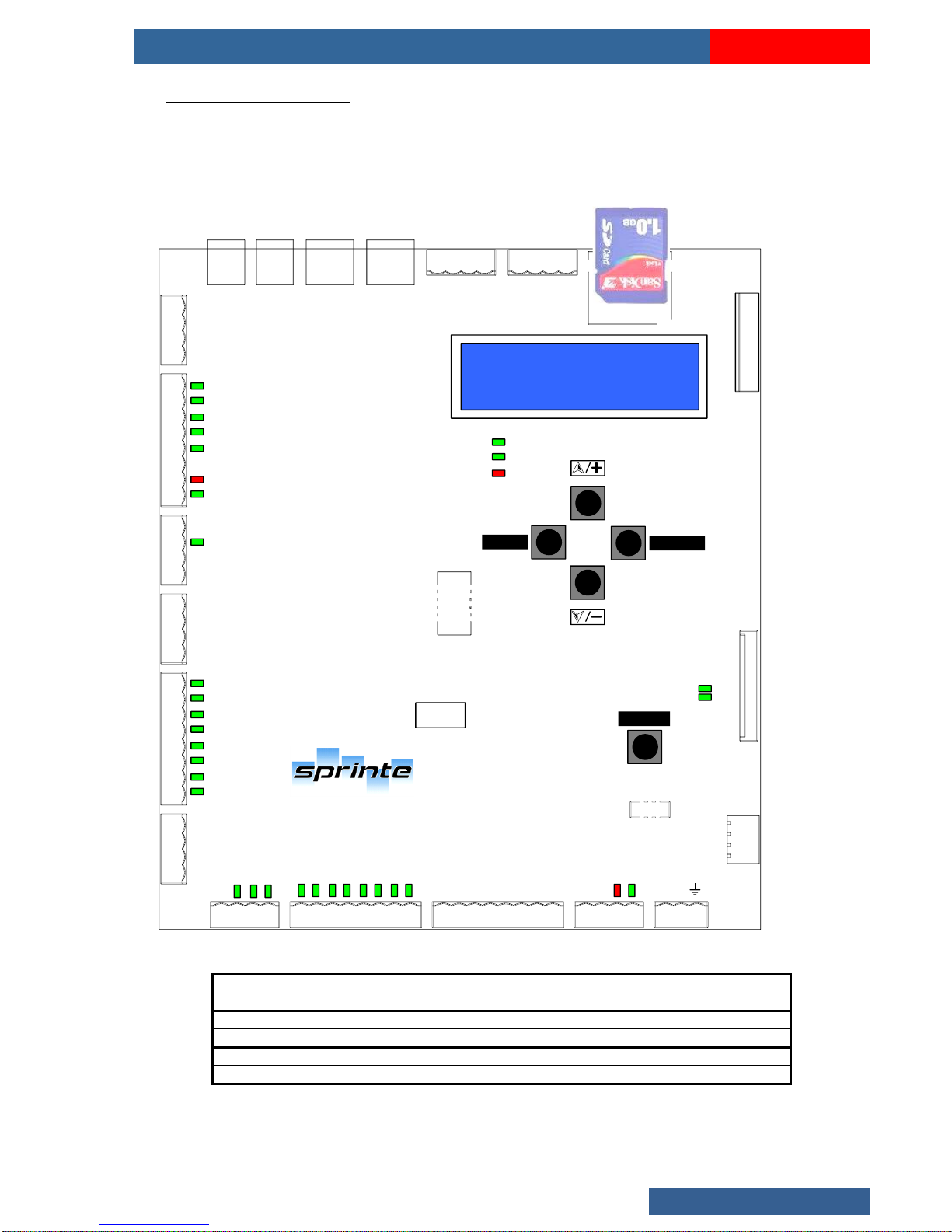
USER MANUAL « ASP 116 EVOLUTION »
BOARDS
Sprinte SAS, All rights reserved, including translation rights
78
5 Electronics boards
5.1 Electronics board in machinery
5.1.1 Lift controller boards « 216SP »
SPRINTE
ASP116 EVOLUTION
BACK
ENTER
RESET
216SP1-A
NUM. CARTE
INDICE
FCF1
PE2-M
V24C
VCC
DFT
PE1-M
PE3-M
PE4-M
PE5-M
PE6-M
TR1-M
TR2-M
TR3-M
AR1-M
MC2-M
ENCODEUR
MC1-M
CN15
CN4-M
CN3-M
GND
V24
V12
GND
PHI
V9
SCL
SDA
CN9-M
CN2-M
CN1-M
CN8-M
CN7-M
CN6-M
CN5-M
CN11-M
FM
FD
AFC
DFT
FCO1
CHC1
CPC1
FAC1
SU
NSC
MI
INS
DI
CCC
DTC
C
B
A
C1
C2
C3
C4
C5
C6
C7
C8
V24
V12
V9
GND
GND
RB
RH
CPO
P1
P2
P3
P4
P5
P6
P7
P8
GND
AFT
V9
V12
PN
V24
FM
FD
GND
GND
TH
GND
STH
MR
GND
VCC
C
OUT
SH
AU
PBISO
FER1
OUV1
PL
CLK
DIN
STR
OE
CN4-M
Connector connecting 216SP controller board to power board 220SP
CN3-M
Connector connecting 216SP controller board to 214SP power supply board
CN11-M
Connector connecting 216SP controller board to 217SP expansion boards
BAC
Page 79
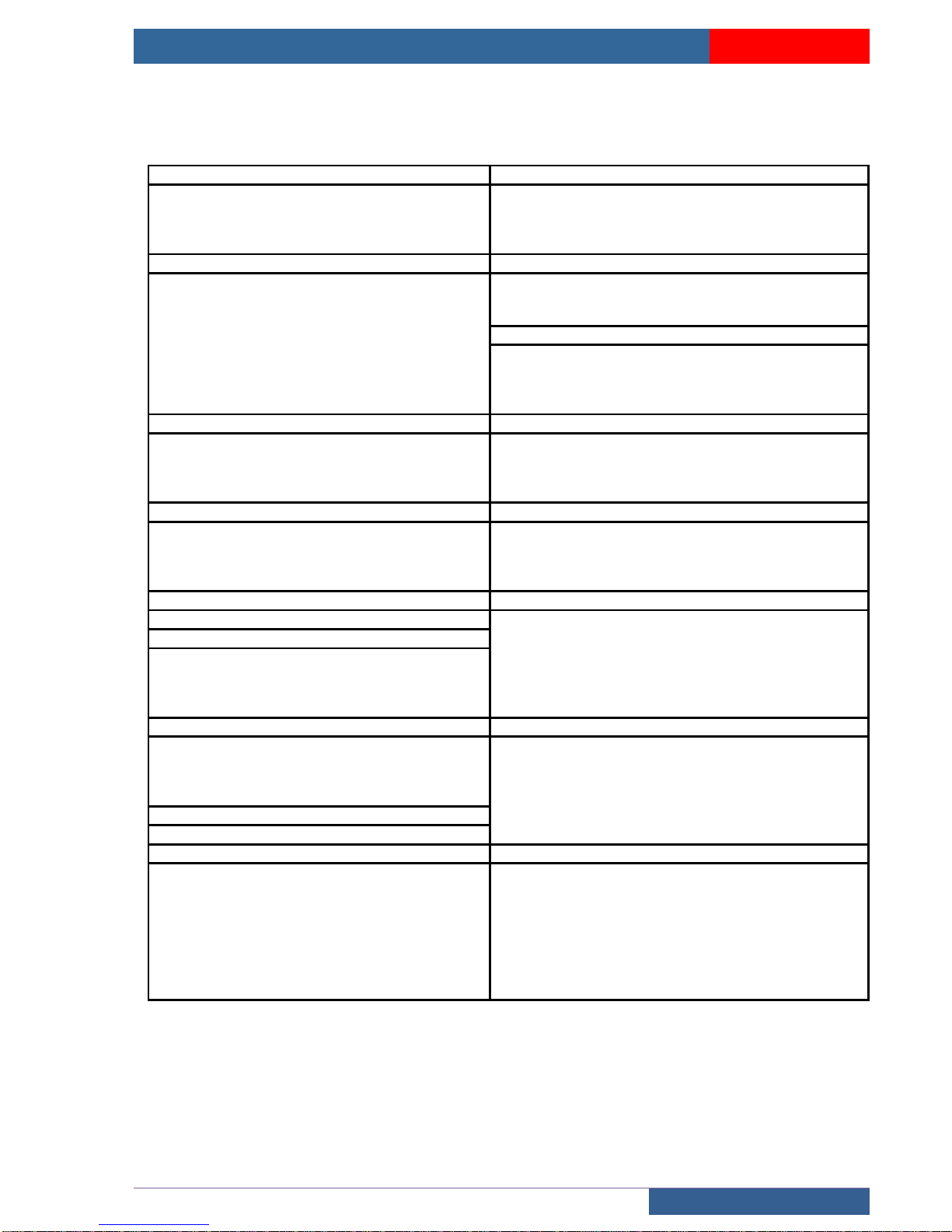
USER MANUAL « ASP 116 EVOLUTION »
BOARDS
Sprinte SAS, All rights reserved, including translation rights
79
outputs « < » ; inputs NO « > » inputs NC « > / »
PE1-M
AR1-M
< FM
(not used)
< GND
ground
< FD
(not used)
< GND
ground
< AF
(not used)
> STH
Oil heat switch
< DFT
Out of service
> MR
Emergency operation switch
PE2-M
MC2-M
> / FCF1
(not used)
> TH
Machinery heat switch
> / FCO1
(not used)
< GND
ground
> CHC1
(not used)
< masse
screening
> / CPC1
(not used)
MC1-M
> FAC 1
(not used)
> 1
(not used)
< GO
GONG
< 2
(not used)
> SU
Overload
< 5
(not used)
> / NSC
No full stop
< 8
(not used)
PE3-M
CN2-M RS485
> MI
Inspection up
< 1
Data – (A)
> INS
Inspection switch
< 2
Data + (B)
> DI
Inspection down
< 3
GND
> CCC
(not used)
< 4
GND
PE4-M
CN1-M RS485
> DTC
(not used)
< 1
Data – (A)
> C
(not used)
< 2
Data + (B)
> B
(not used)
< 3
GND
> A
(not used)
< 4
GND
PE5-M
CN5-M
>C1 à C8
Car and floor buttons
< 1
24 V
PE6-M
< 2
ground
< V24
24 V DC
< 3
24 V
< V12
12 V DC
< 4
ground
< V9
9 V DC
< 5
CANH
< GND
ground
< 6
CANL
TR1-M
CN6-M
< GND
ground
< 1
24 V
> /RB
(not used)
< 2
GND
> /RH
(not used)
< 3
24 V commanded
> /CPO
Fire man key
< 4
ground
TR2-M
< 5
CANH
> P1 à P8
Car and floor buttons
< 6
CANL
TR3-M
CN7-M et CN8-M
< GND
ground
< 1
24 V
< AF
Landing display
< 2
GND
< V9
(not used)
< 3
24 V
< V12
12 V DC
< 4
ground
< PN
ground
< 5
(not used)
< V24
24 V DC
< 6
(not used)
< FM
Up arrow
< 7
CANH
< FD
Up arrow
< 8
CANL
Page 80
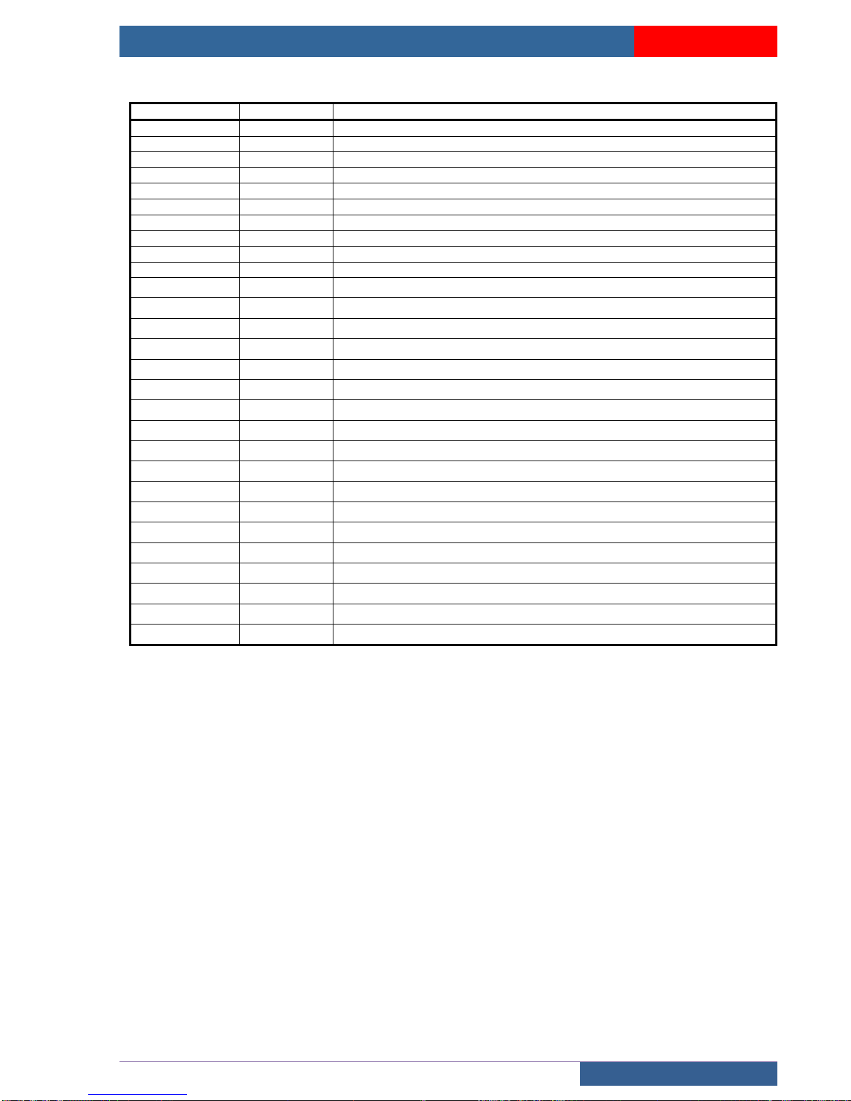
USER MANUAL « ASP 116 EVOLUTION »
BOARDS
Sprinte SAS, All rights reserved, including translation rights
80
LED
STATUS
INFORMATION
V24C
ON
24V commanded
VCC
ON
216SP board powered
DFT
ON
Indicates that the device is not working the LED flashes if boot is faulty
CABINE
MACHINE
MULTIPLEX
FCF1
ON
(not used)
FCO1
ON
(not used)
CHC1
ON
(not used)
CPC1
ON
(not used)
FAC1
ON
(not used)
SU
ON
110% of maximum authorised car load reached.
NSC
ON
80% of maximum authorised car load reached.
INS
ON
(not used)
CCC
ON
(not used)
DTC
BLINK
(not used)
C
OFF
(not used)
B
OFF
(not used)
A
OFF
(not used)
C1 à C8
ON
Sending taken into account.
RB
ON
(not used)
RH
ON
(not used)
CPO
ON
Fireman’s key activated.
P1 à P8
ON
Call taken into account.
STH
ON
(not used)
MR
ON
Control panel in emergency mode
OUV1
ON
Door 1 opening command activated.
FER1
ON
Door 1 closing command activated.
Page 81
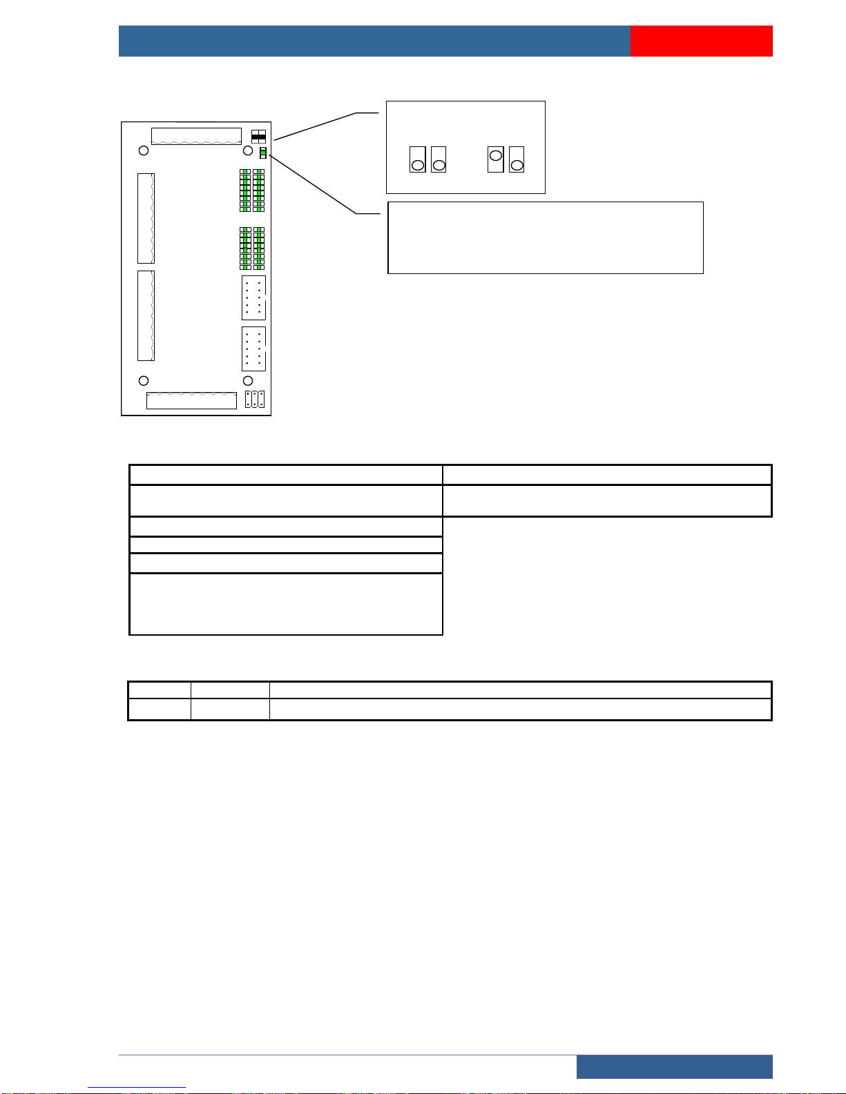
USER MANUAL « ASP 116 EVOLUTION »
BOARDS
Sprinte SAS, All rights reserved, including translation rights
81
5.1.2 217SP expansion board
ES4-X
X25 X26 X27 X28 X29 X30 X31 X32
ES1-X
X1
X2
X3
X4
X5
X6
X7
X8
ES2-X
X9
X10
X11
X12
X13
X14
X15
X16
ES3-X
X17X18X19X20X21X22X23X24
1 2
SW1
CN1
CN2
217SP
1
2
3
4
5
6
7
8
17
18
19
20
21
22
23
24
9
10
11
12
13
14
15
16
25
26
27
28
29
30
31
32
CN3
outputs « < » ; inputs NO « > » inputs NC « > / »
CN1
CN2
Connector connecting the 217SP expansion board
to the 216SP board
Connector connecting the 217SP expansion board no.
2 to the 217SP expansion board no. 1
CN3
Not used
ES1-X, ES2-X, ES3-X, ES4-X
X1 à X32
Expansion board inputs / outputs
X25
BUZZER output forced closing of
doors
X26
Service 1 nudging output
LED
STATUS
INFORMATION
1 à 32
OFF
Expansion board inputs / outputs activated
SW1
1 - 2
SW1
1 - 2
EXT 1
EXT 2
Board state
OFF : board has no power supply
FLASH ON: board has power supply and the Bus is OFF
ON : board interacts with its bus
Page 82
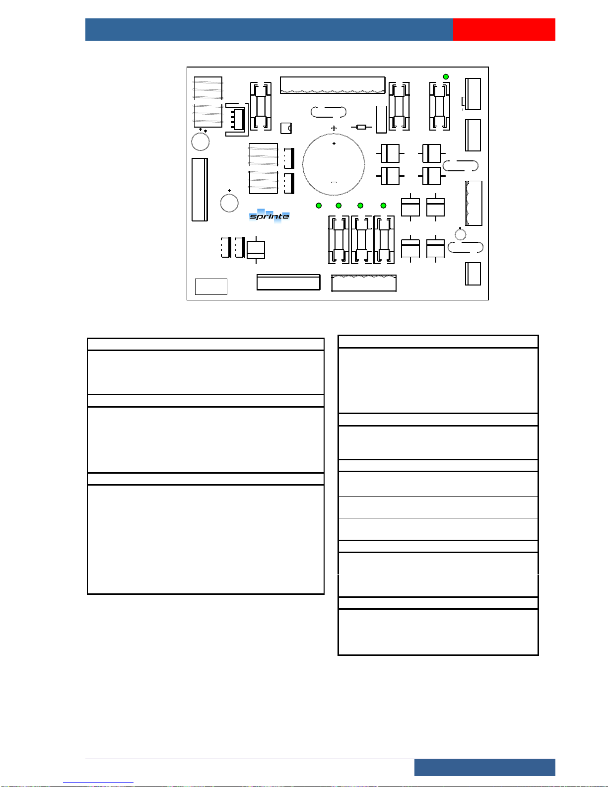
USER MANUAL « ASP 116 EVOLUTION »
BOARDS
Sprinte SAS, All rights reserved, including translation rights
82
5.1.3 214SP Power supply board
214SP-A
NUM. CARTE
INDICE
V12
V24
5A
FC+5ACHS
2A
CN3-A
GND
V24
V12
GND
PHI
FU1
2A
TS1-A
L1380
T380
T220
L1220
220F
220F
T0
L2
L3220
L3
380
FU2
FU3
BATT380
2A
T0
5A
AR1-A
BATBAT+
CFG
24V
AR2-A
GND
FCT
FC-
FC+
AR3-A
GND
V24
22V
CHS
CF1-A
C55
CFC
C70
TS2-A
7055011011002222
CN4-A
V12
FC+
CHS
FC-
V12
V24
FU4
FU5
FU6
CN3-A CN3-M / 216SP
V24
24 V dc
V12
12 V dc
GND
ground
PHI
Detection of reversal or missing phase
CN4-A CN2-I / 220SP, CN2-0 / 225SP
V24
24 V dc
V12
12 V dc
GND
ground
FC-
-55 V or -70 V dual alternating
FC+
+55 V or +70 V dual alternating
CHS
110 Vac safety chain
TS1-A transformer, terminal block
L1.380
Entry 400V mains GRID (400V TRI)
T380
Entry 400V from transfo
T220
Output 230V from transfo
L1.220
Entry 230V mains EDF (230V MONO)
220F
Output 230V from transfo
220F
Output 230V from transfo
T0
Output 0V from transfo
L2
Entry 400V mains EDF (400V TRI)
L3.220
Entry 230V mains EDF (230V MONO)
L3.380
Entry 400V mains EDF (400V TRI)
TS2-A transformer
22
Output 22V from transfo
022
Output 0V from transfo
0110
Output 0V from transfo
110
Output 110V from transfo
55
Output 55V from transfo
70
Output 70V from transfo
CF1-A (configuration brake voltage)
C55
Configuration FC+ / FC- in 55V
CFC
Common Configuration FC+ /FC-
C70
Configuration FC+ / FC- in 70V
AR1-A battery, load configuration
BAT-
Battery supply -
BAT+
Battery supply +
CFG
24V
Config. battery charge in 24Vdc
CFG
24V
Config. battery charge in 24Vdc
AR2-A contactors
GND
ground
FCT
Brake / cam timed
FC-
-55 V or -70 V dual alternating
FC+
+55 V or +70 V dual alternating
AR3-A voltage outputs
GND
ground
V24
24 V dc
22V
Info 24V not safeguarded (max 5A)
CHS
110 Vac safety chain
Page 83
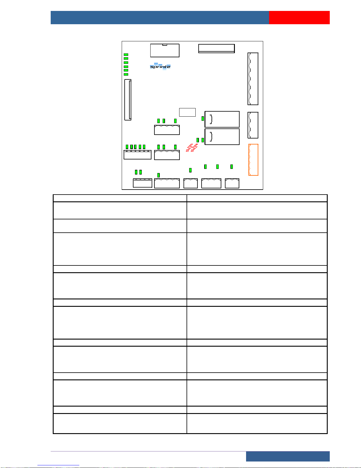
USER MANUAL « ASP 116 EVOLUTION »
BOARDS
Sprinte SAS, All rights reserved, including translation rights
83
5.1.4 220SP motor interface board
DHCS_AMONT
DHCS_AVAL
AU
SHP
SHC
VER
CN1-I
CHAUF
V24
VENT
BOOST
CN6-I
FER 2
V24
OUV2
CAM 2
FER 1
V24
OUV1
CAM 1
CN9-I
CN11-I
CN12-I
CN13-I
CN14-I
ST
GND
CFR1
STH
GND
CFR2
STH
CC
GND
CN10-I
E1 E2 E3 E4
S1
CN8-I
S2S3S4
S5
COM
OUT
IN
K_LIGNE
K_EGA
ATTENTION RISQUE DE CHOC
ELECTRIQUE
CN2-I
CN3-I
CN5-I
CN7-I
CN4-I
GND
VCC
C
OUT
FER1
OUV1
PL
CLK
DIN
STR
OE
PE
VER
SHP
AU
RV
CHS
VER
CCT
L
K-EGA
E-EGA -
E-EGA +
PE
K_LIGNE
NUM. CARTE
INDICE
220SP1-A
CN1-I
CN2-I
Connector connecting the 220SP power board to
the 225SP and 226SP expansion boards
Connector connecting the 220SP to the 214SP power
supply board
CN3-I
Safety chain inputs: 48-230Vac or 24Vdc
CN4-I
>PE
Connector connecting the 220SP power board to the
216SP board
>VER
Locking
>SHP
Landing shunt
>AU
Emergency stop
>CHS
Safety chain power supply
CN5-I
CN6-I
<VER
Locking
<BOOST
Brake boost control
<CCT
Common contactor
<VENT
Fan control
<L
Line
V24 <CHAUF
Heating control
CN7-I
CN8-I
< K_EGA
Shaft lighting control
<S1 … S5
VF controls
> E_GA
Shaft lighting detection
Opto-isolated / 24 Vdc to 230
Vac
COM
PE
CN9-I
CN10-I
<CAM 2
Door 2 cam control
>E1
Opto-isolated / 12-24 Vdc
<OUV 2
Door 2 opening control
>E2
Opto-isolated / 12-24 Vdc
V24
24 V
GND
<FER 2
Door 2 closing control
GND
CN11-I
CN12-I
<CAM 1
Door 1 cam control
>ST
Thermal probe
<OUV 1
Door 1 opening control
GND
V24
24 V
<FER 1
Door 1 closing control
CN13-I
CN14-I
>STH/CFR1
Oil thermal probe / Brake state
>CC
Contactors control
GND
GND
GND
>SPR/CFR2
Brake state
Page 84
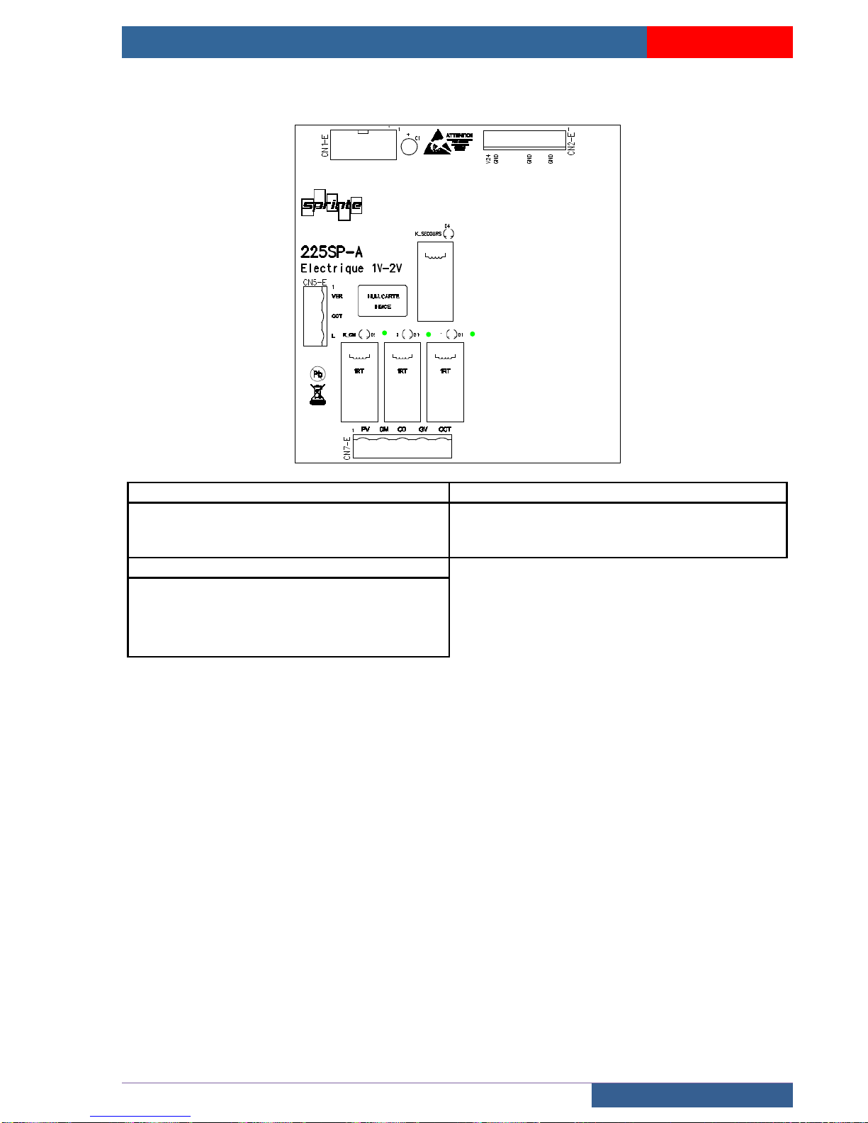
USER MANUAL « ASP 116 EVOLUTION »
BOARDS
Sprinte SAS, All rights reserved, including translation rights
84
5.1.5 225SP Expansion board 2 speeds motor
CN1-0
CN2-0
Connector connected to CNI-I connector of 220SP
power board
Connector connected to CN4-A connector of 214SP
power supply board and to CN2-I connector of 220SP
board
CN7-0
<PV
Low speed contactor
<CM
Up contactor
<CD
Down contactor
<GV
High speed contactor
<CCT
Common contactor
Page 85
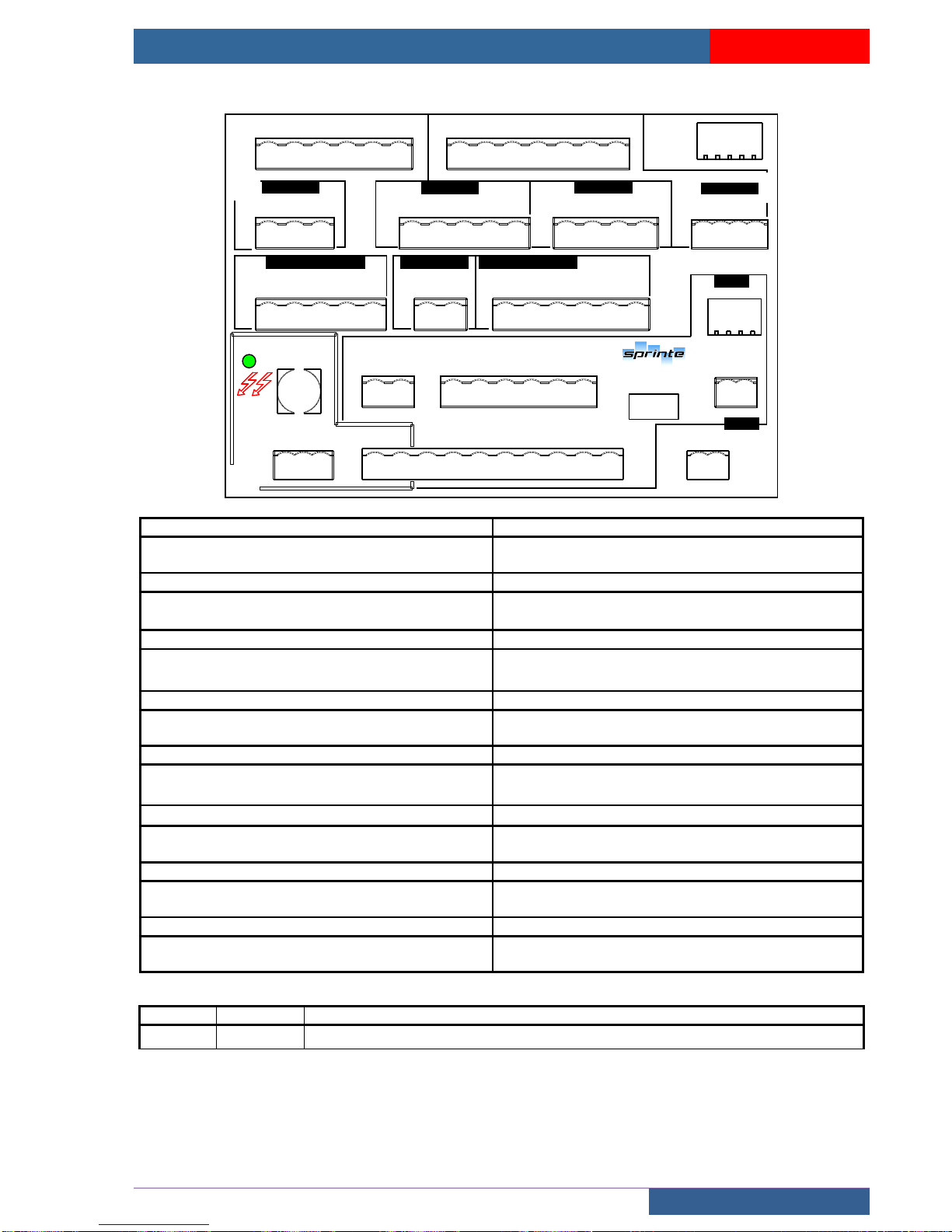
USER MANUAL « ASP 116 EVOLUTION »
BOARDS
Sprinte SAS, All rights reserved, including translation rights
85
5.1.6 212SP safety chain distribution board
NUM. CARTE
INDICE
AR1
LIMITEUR
CHS
212SPA
ATTENTION RISQUE DE
CHOC ELECTRIQUE
AU
RV
SHP
PE
VER
MC1
AU
CHS
COHD
MR2
INC1
MR1
STMA
AR2
MC2
PCU
PE
RV
BUTEES
TR1
PE
COHD
AU
FCDI
FCMI
INS-CU
TR2
MR1
INC1
PCU
STMA
RAPPEL
GND
RAPMRDR
CAN
MC3
PE1
TR3
AU
PE
SHP
VER
VERC
MC4
COHD
BLP2
PORTES PALIERES INH NORMAL
TR4
EXTREMITES GAINE
RV
MR1
FCB
FCH
PE
PCU
PE3
TEL2
TEL1
TEL.
MC6
TEL2
TEL1
PE2
VER
PE
PE5
BLP2
FCDI
PE
FCB
FCMI
MC5
LCP
N
LCP-5A
N
LCP
SHP
PE
VERC
MR2
MR1
AU
STMA
FCH
PE4
AR1
MC1
Connector connecting 212SP board 220SP boards
(Safety chain taking information)
Connector connecting call operation to 212SP board
(Safety chain)
MC2
TR1
Connector connecting speed limiter to 212SP board
Connector connecting the end stops (reduced standby option)
TR2
MC3
Connector connecting pit inspection (Pit inspection
option)
Connector connecting emergency operation to 212SP
board (command)
TR3
MC4
Connector connecting the shunts and landing
lockings (door securities)
Connector connecting top, bottom control (reduced
stand-by option)
TR4
PE2
Connector connecting shaft safety mechanisms
(Stop pit, tightener pulley etc…..)
Connector linking trailing cable to 212SP to 210SP
boards (levelling safety)
PE5
PE3
Connector connecting trailing cable to 212SP to
221SP boards (reduced stand-by + pit inspection)
Connector connecting the trailing cable to 212SP to
210SP boards (telephone line)
MC5
PE4
Connector connecting car light DTU entry to the
212SP board
Connector connecting the trailing cable to 212SP to
210SP boards (main safety chain)
MC6
AR2
Connector connecting telephone line entry to
212SP board
Connector connecting the 212SP board to the 216SP
board (Call information + CAR CAN BUS)
LED
STATUS
INFORMATION
LCP
On
Continuous 230V power supply (Car lighting)
Page 86
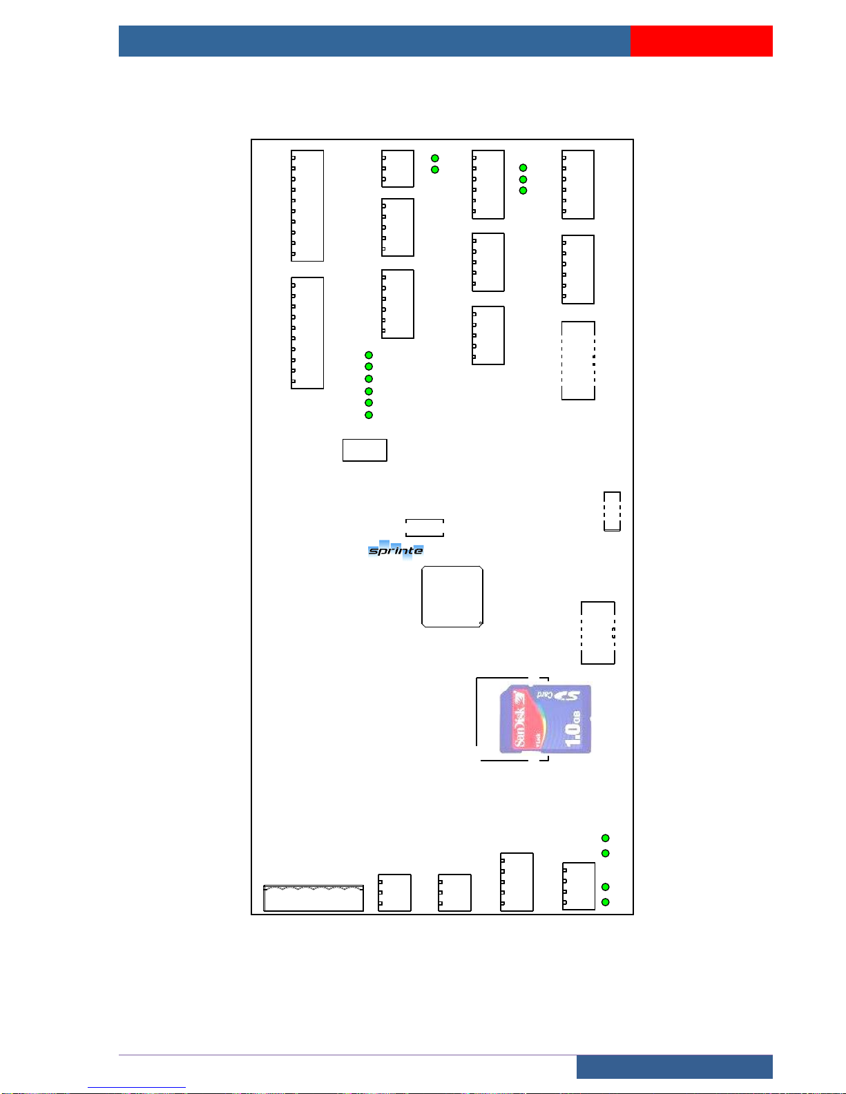
USER MANUAL « ASP 116 EVOLUTION »
BOARDS
Sprinte SAS, All rights reserved, including translation rights
86
5.2 Electronic cars in inspection box
5.2.1 211SP car controller board
CB1
211SP2-A
NUM. CARTE
INDICE
V24C
V24
V12
ETAT
RB
RH
A
D
B
CPC1
CHC1
DIS
INS
SHC
DHCS_AVAL
C1
C3
C5
C7
FM
BPALR
FAC1
HP1C
GND
V24C
C2
C4
C6
C8
FD
ECL
OAC1
AF
PE
GND
GND
GND
GND
CB2
PE
CB9
C9
C11
VALJ
SIR
FMP
V12
VSU
VISU1
VISU2
V24C
C10
C12
VALV
VCOM
FDP
CCC
VINS
DFT
PE
GND
CB5
BFER1
INS
MI
V24C
BOUV1
LUG
DI
GND
BAB1A
BAB1B
RALENTISSEURS
INSPECTION
OPER. PORTE1
CB8
GND
CHC1
CPC1
FCF1
FCO1
HP1P
GND
COM
NUD1
FER1
V24C
OUV1
LECTEUR
C
Y12
Y22
CB3
GND
GND
V12
GND
Y11
Y21
CB4
GND
CAP2
V24C
GND
CAP4
GND
CAP1
V24C
V24C
GND
CAP3
V24C
JAUGES
TELEPHONE
VALJ
GND
VALV
DIS
CB6
V12
SIR
V12
DIS
V24
PE
PESE CHARGE
GND
GND
GND
GND
CB7
SU
NSC
V24C
PR
INH
V24C
VISU2
VISU1
CN1
Y12
GND
Y22
VISO
CB10
Y11
Y21
V24C
VISO
IRS
GND
RELAIS SECU
CB14
CB12
RS485
CB13
CAN1
CB11
PE1
CN3
CN6
Page 87
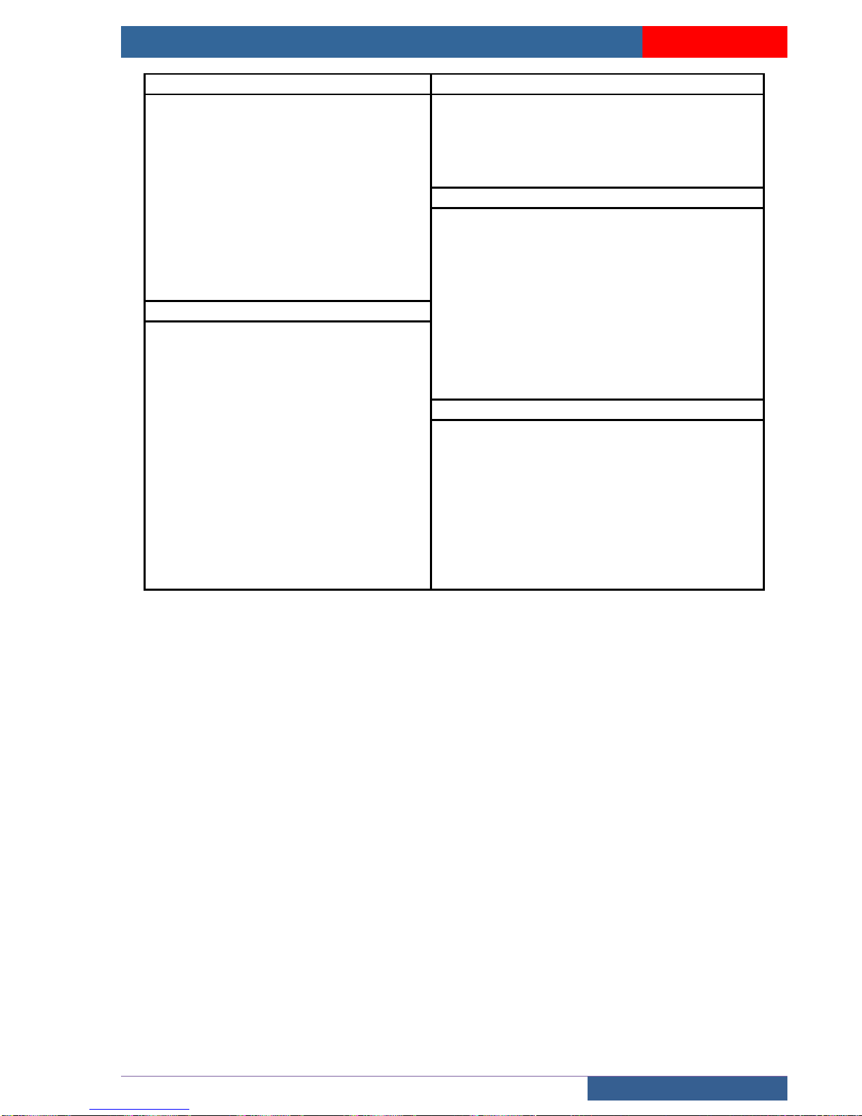
USER MANUAL « ASP 116 EVOLUTION »
BOARDS
Sprinte SAS, All rights reserved, including translation rights
87
CB1 - BAB 1A
CB2 - decelerators
<V24C
24 V controlled
<GND
ground
<GND
ground
>RH
Top decelerator
>C1 to C8
Car button 1 to 8
<GND
ground
<FM
Up arrow
>RB
Bottom decelerator
<FD
Down arrow
<GND
ground
>BPALAR
Alarm button
<PE
Equipotential protection
>ECL
Emergency lighting
CB3 - Reader
>FAC1
Accelerated closing service 1
<V12
12 V
>OAC1
Accelerated opening service 1
>D
Reader fault
>HP1C
Car loud speaker
<GND
ground
<AF
Display
>A
Reader input A
<GND
ground
<GND
masse
<PE
Equipotential protection
>B
Reader input B
CB4 – load weighing gauge
<GND
ground
<V24C
24 V controlled
>C
Reader input C
<V24C
24 V controlled
>Y11
ILS1 input for levelling
<GND
ground
>Y12
ILS1 input for levelling
<GND
ground
>Y21
ILS2 input for levelling
>CAP1
Input gauge 1
>Y22
ILS2 input for levelling
>CAP2
Input gauge 2
CB5 – inspection
<V24C
24 V controlled
<V24C
24 V controlled
<V24C
24 V controlled
<GND
ground
<GND
ground
>BFER1
Closing button service 1
<GND
ground
>BOUV1
Opening button service 1
>CAP3
Input gauge 3
>INS
Inspection button
>CAP4
Input gauge 4
>LUG
Shaft light button
>MI
Inspection up
>DI
Inspection down
>BTELI
Telephone button
>BTELI
Telephone button
Page 88
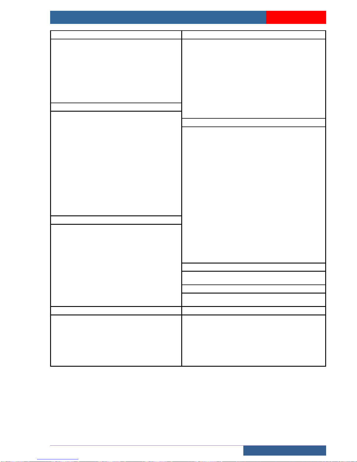
USER MANUAL « ASP 116 EVOLUTION »
BOARDS
Sprinte SAS, All rights reserved, including translation rights
88
CB6 – telephone
CB7 – load weighing
<V12
12V
<V24C
24 V controlled
<GND
ground
<GND
ground
<V12
12V
>SU
Overload
<GND
ground
<GND
earth
<BTELI
Telephone button
>NSC
Non stop full
<BTELI
Telephone button
<GND
ground
< DIS
Discriminator (dry contact)
>PR
Presence
< DIS
Discriminator
<GND
ground
<V24
24 V
>INH
Inhibiting load weighing
<PE
Equipotential protection
<V24C
24 V controlled
CB8 – Door 1 operator
>VISU1
Analogue overload display
<HP1P
Landing loud speaker
>VISU2
Analogue overload display
<V24C
24 V controlled
CB9 – BAB 1B
<GND
ground
<V24C
24 V controlled
<GND
ground
<GND
Earth
<CHC1
Shock
>C9 à C12
Car button 9 to 12
<COM
Common outputs opto-coupled
doors
VALJ
Yellow remote alarm indicator light
>CPC1
Cell safety
VALV
Green remote alarm indicator light
>NUD1
Opto-coupled control of forced
door closing
>BTELI
Telephone button
>FCF1
Closing end limit
>BTELI
Telephone button
<FER1
Opto-coupled control of door
closing
<FMP
Arrow next departure up
>FCO1
Opening end limit
<FDP
Arrow next departure down
<OUV1
Opto-coupled control of door
opening
<V12
12V
CB10 – Safety relay
CCC
Car priority key
<V24C
24 V controlled
<VISU
Output overload indicator light
<GND
Earth
<VNSC
Output non stop full indicator light
<Y11
ILS1 input to safety relay
<VISU1
Overload analogue display
<Y12
ILS1 input to safety relay
<DFT
Output out of order indicator light
<Y21
ILS2 input to safety relay
<VISU2
Overload analogue display
<Y22
ILS2 input to safety relay
<PE
Equipotential protection
<VISO
Levelling request
CN1 – connection 210SP
<VISO
Levelling request
Connector connecting the 211SP board to the 210SP
board
>IRS
Safety relay status
CN6 – connection 223SP
<GND
Earth
Connector connecting the 211SP board to the 223SP
boards
PE1 – CANBUS machinery
CB12 –RS485 expansion
>V24
Input 24 V
<V24C
24 V controlled
>GND
ground
<GND
ground
>V12
Input 12V
<RS485_H
Output RS485
BLI
CANBUS shielding
<RS485_L
Output RS485
(reserved)
<V24C
24 V controlled
(reserved)
<GND
ground
>CAN0_H
Input CANBUS 0 HIGH
>CAN0_L
Input CANBUS 0 LOW
Page 89
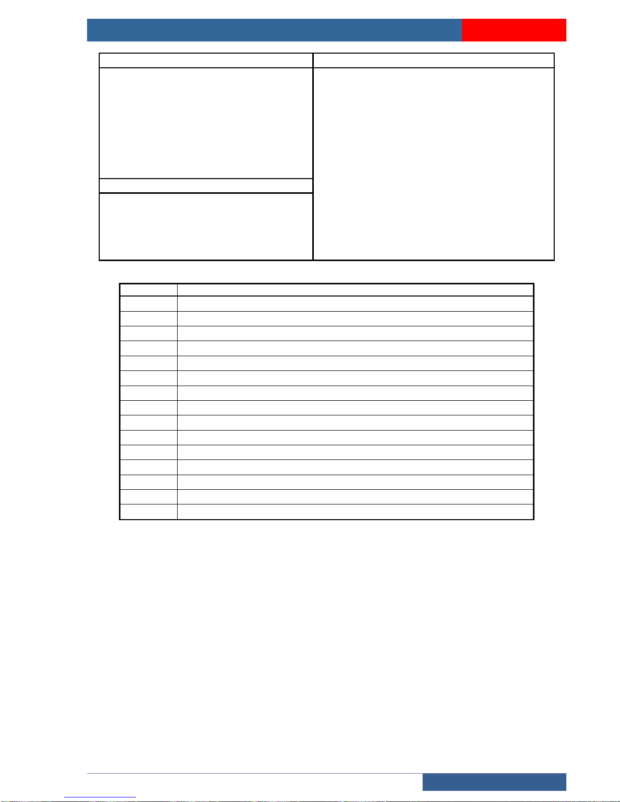
USER MANUAL « ASP 116 EVOLUTION »
BOARDS
Sprinte SAS, All rights reserved, including translation rights
89
CB11 – CANBUS / RS485 expansion
CB13 – CANBUS output
<V24
24 V
<V24C
24 V controlled
<GND
ground
<GND
ground
(reserved)
<GND
ground
(reserved)
>BLI
Shielding
<SCD_SUIV
Next control
<CAN1_H
CANBUS 1 HIGH
>BLI
Shielding
<CAN1_L
CANBUS 1 LOW
<RS485_H
Output RS485
<RS485_L
Output RS485
<CAN0_H
CANBUS 0 HIGH
<CAN0_L
CANBUS 0 LOW
CB14 – Power supplies
<V24
24 V
<GND
ground
<V24
24 V
<GND
Earth
<V12
12 V
<GND
ground
LED
INFORMATION
CHC1
Shock Input
CPC1
Cell output
DIS
Discriminator output
INS
Inspection input
ISHC
IDHCS_AV
RH
Top decelerator
RB
Bottom decelerator
A
Reader A input
B
Reader B input
C
Reader C input
ETAT
CANBUS status
V12
12 V present
V24
24 V present
V24C
24 V controlled present
Page 90
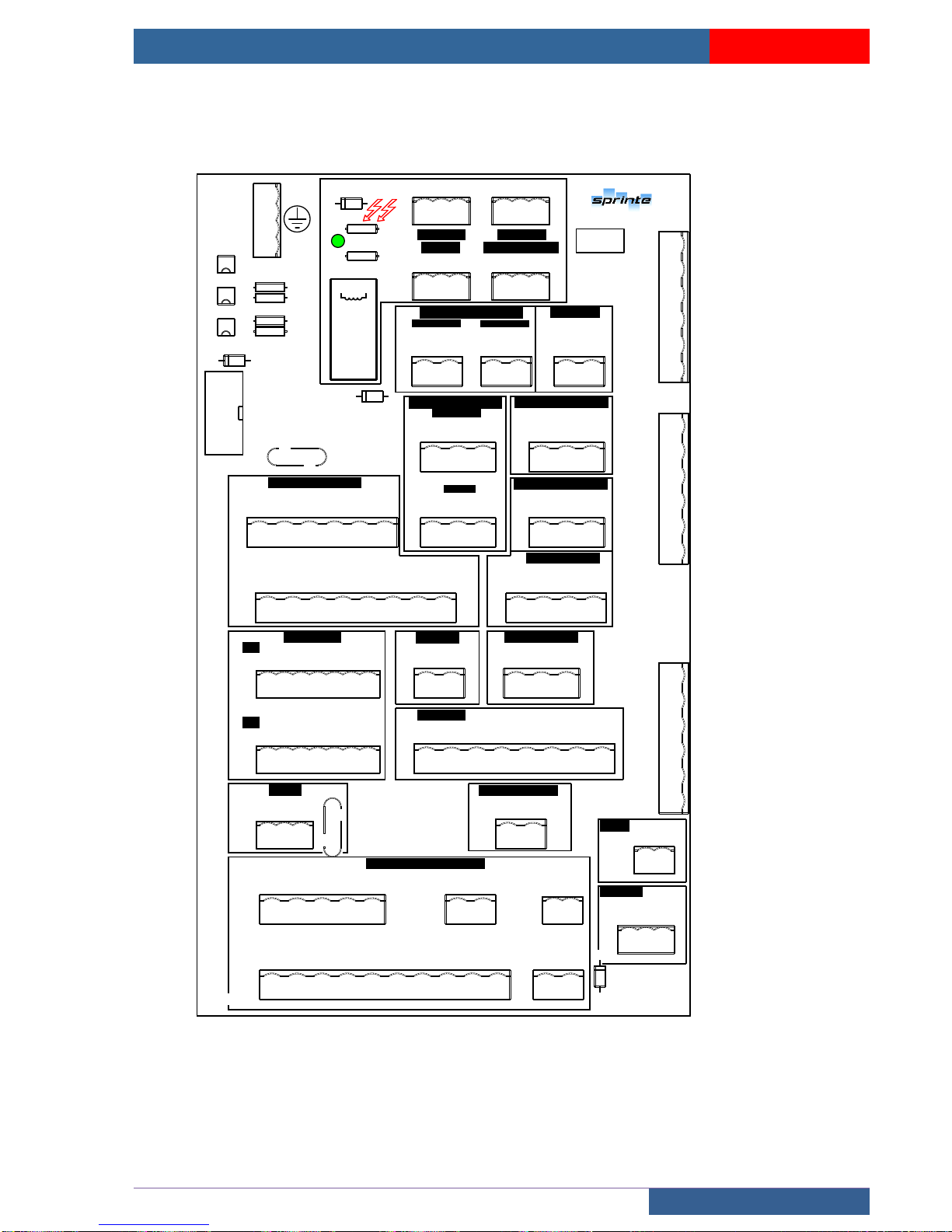
USER MANUAL « ASP 116 EVOLUTION »
BOARDS
Sprinte SAS, All rights reserved, including translation rights
90
5.2.2 210SP safety chain distribution board
PE
LC A
CB3
CB2
CB5
CB4
N
PE
LC A
N
LU MIERE
AU TO.
LCP
PE
LC P
N
PE
LC P
N
LU MIERE
PE RMANE NTE
CN1
210SP1-A
CB6
CB7
CB8
CN2
CB1
FD C INS PECTI ON
MI CA
FC MI1
HA U T
BA S
DI CA
FC DI
IN S1
FC CH
DH C S
CB9
CB10
CB11
CB12
CB13
BA LUSTR ADE
BL P2
PE
IN C2
DE P LIEE
IN S2
PE
BL P2
PL I EE
PA RACHU TE
PA R1
PE
IN S1
PA R1
PE
GP 1
GA RDE - PIED
CN3
CN4
MI CA
DI CA
FC CH
FC MI1
IN C2
FC DI
IN SPECT ION
PE
N
LC P
MI CA
DI CA
BL P2
CB14
MR 1
MR 2
ST MA
ST C1
IN C2
IN S2
GP 1
PA R1
CB15
DE TECT 1m
PA R1
GP 1
DE T 1M
GN D
TR APPE
ST C2
PE
TR AP
ST OP 2
ST C1
ST C2
CB18
CB17
CB16
22 0F
PE
22 0F
GN D
CP C2
GN D
V2 4
CE LLULE S
2
CB19
22 0F
PE
22 0F
GN D
CP C1
GN D
V2 4
1
PO RTE1
CB20
K1
L1
M1
PE
SH P
SH C1
SH C
VE RC1
22 0V
CB21
IS ONIVE LAGE
CB22
22 0F
PE
22 0F
VE R
AU
CB23
TE L.
TE L1
TE L2
CB24
CA ME 1
CA M1-
PE
CA M1+
PE NDENT IFS C ABINE
22 0F
22 0F
K1
L1
M1
PE6
PE2
VE R
PE
PE3
TE L1
TE L2
PE7
CA M1+
CA M1-
PE4
N
LC P
SH P
VE RC
PE
MR 2
AU
MR 1
FC H
ST MA
SH C 1
SH C
VE R C1
VE R C
PE
OP TION PORTE 2
OP TION RESER V ES RE DUITE S
GN D
IF SU
FC H
BL P2
AU
TR AP
NU M . CA R TE
IN D ICE
AT T ENTI O N RI S Q UE D E
CH O C EL E CTRIQ U E
Page 91
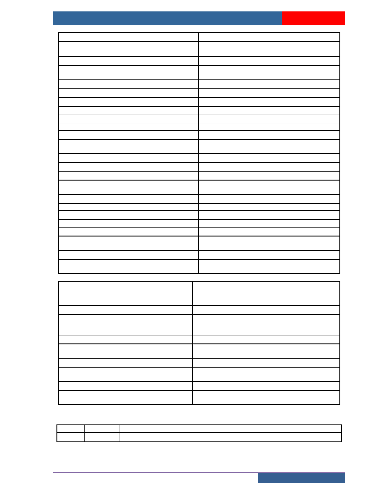
USER MANUAL « ASP 116 EVOLUTION »
BOARDS
Sprinte SAS, All rights reserved, including translation rights
91
AR1
CB2
Earths connection (PE)
Connection of automatic car light 230V (managed
by timer)
CB3
CB4
Connection of continuous car light 230V
Connection of automatic car light 230V (managed
by timer)
CB5
CB6
Connection of continuous car light 230V
Connection of top inspection end limit
CB7
CB8
Connection of bottom inspection end limit
Connection of top and bottom inspection end limit
CB9
CB10
Connection of folded out balustrade
Connection of safety gear
CB11
CB12
Connection of inspection box (Inspection safety +
plug car roof)
Connection of folded up balustrade
CB13
CB14
Connection of automatic or manual toe-guard
Connection of inspection box (Inspection safety)
CB15
CB16
Connection of rocker detection 1 m for automatic
toe-guard + contact toe-guard status
Cell connection by 24Vdc or 230Vac (DOOR2)
CB17
CB18
Connection of 2nd service stop
Connection of car trap-door
CB19
CB20
Cell connection by 24Vdc or 230Vac (DOOR1)
Connection door 1 motor power supply + door safety
CB21
CB22
Additional 230V power supply (Power supply
provided by transfo in control panel)
Connection of safety relay (levelling door open)
CB23
CB24
Connection telephone line on telephone
Connection cam 1 (power supply configurable in
control panel)
PE2
PE3
Connector connecting trailing cable to 210SP to
212SP boards (Levelling safety)
Connector connecting trailing cable to 210SP to
212SP boards (telephone line)
PE4
PE6
Connector connecting trailing cable to 210SP to
212SP boards (main safety chain)
Connector connecting trailing cable to terminals in
control panel (Power supply 220F + Power supply
motor)
PE7
CN1
Connector connecting trailing cable to terminals
in control panel (Power supply cam 1)
Connector connecting 210SP board to the 221SP
board (reduced stand-by + pit inspection option)
CN2
CN3
Connector connecting 211SP board to 210SP
board
Connector connecting 210SP board to the 221SP
board (reduced stand-by + pit inspection option)
CN4
Connector connecting 210SP board to 222SP
board (Option 2nd door service)
LED
STATUS
INFORMATION
LCP
On
Continuous 230V power supply (Car lighting)
Page 92
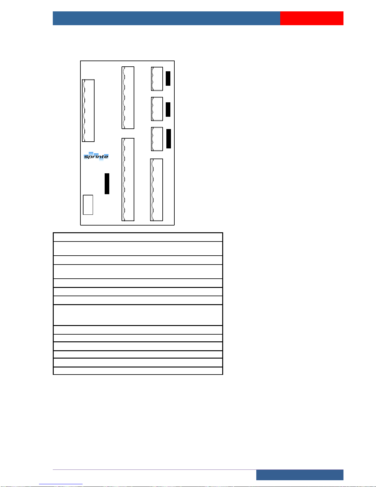
USER MANUAL « ASP 116 EVOLUTION »
BOARDS
Sprinte SAS, All rights reserved, including translation rights
92
5.2.3 222SP power board for door second service
CN1
SHC1
SHC
VERC1
VERC
PE
IO1
IF1-EF1
IO2
PE
IF2-EF2
IE-
IO1
IF1-EF1
IE-
PE9
CB28
CB29
IO2
IF2-EF2
IE-
CAM2+
PE
CAM2-
CB30
CB31
PE10
CAM2+
CAM2-
PE
M2
L2
K2
VERC1
VERC
SHC
SHC1
PE
M2
L2
K2
INJ.1INJ.2
CAME 2
PORTE 2
NUM. CARTE
INDICE
222SP-A
CN4
Connector connecting 222SP board to 210SP board (Option
door 2nd service)
PE9
Connector connecting the trailing cable to terminals in the
control panel (Power supply motor brake injection door 1 & 2)
CB31
Connection power supply motor door 2 + door safety
PE10
Connector connecting the trailing cable to terminals in the
control panel (Power supply motor door 2 + power supply cam
2)
CB30
Connection cam 2 (power supply configurable in control panel)
CB29
Connection motor brake injection door 2
CB28
Connection motor brake injection door 1
Page 93
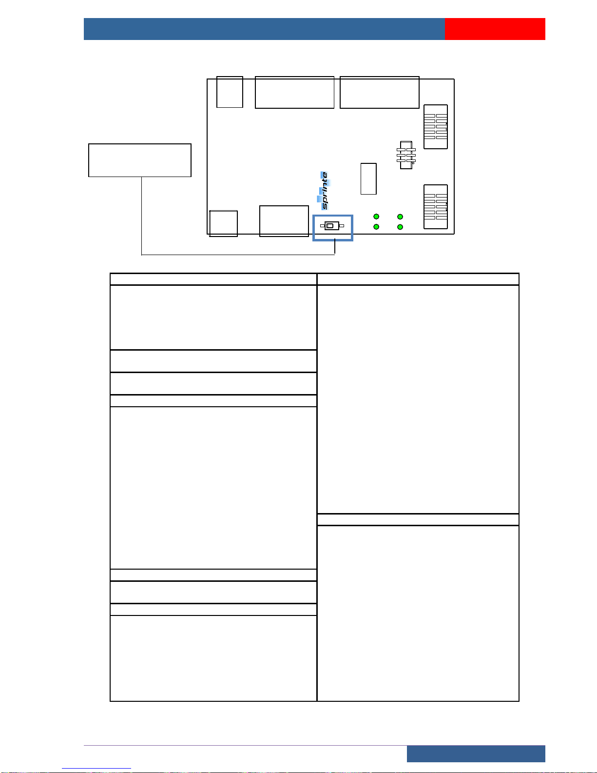
USER MANUAL « ASP 116 EVOLUTION »
BOARDS
Sprinte SAS, All rights reserved, including translation rights
93
5.2.4 223SP extension board for door second service
223SP1-A
CHC2
CPC2
ETAT
V24C
CN3
CN2
CN1
CB34
CB33
CB32
CB35
CB36
NUM. CARTE
INDICE
GND
V24C
BOUV2
BFER2
PE
GND
V24C
C2C1C4
C3C6C5C8C7
FD
FM
ECL
BPALR
OAC2
FAC2
AF
HP2C
PE
GND
GND
V24C
C10
C9
C12
C11
FDP
FMP
CCC
V12
VNSC
VSU
PE
V12
GND
FCO2
OUV2
FCF2
FER2
CPC2
NUD2
CHC2
COM
GND
GND
HP2P
V24C
CB32 inspection
CB34 BAB 2B
<V24C
24 V controlled
<V24C
24 V controlled
<GND
ground
<GND
ground
>BFER2
Closing button door 2
>C9 à
C12
Car button 9 to 12
>BOUV2
Opening button door 2
(not used)
<PE
Equipotential protection
(not used)
CB35 Power supply
((not
used)
>V12
Input 12 V
(not used)
<GND
ground
<FMP
Next up departure arrow
CB36 Door 2 operator
<FDP
Next down departure arrow
<HP2P
Landing loud speaker
<V12
12V
<V24C
24 V controlled
CCC
Car priority key
<GND
ground
<VSU
Overload light indicator output
<GND
ground
<VNSC
<CHC2
Shock
(not used)
<COM
Common outputs opto-coupled
doors
(not used)
>CPC2
Cell safety
(not used)
>NUD2
Opto-coupled control for forced door
closing
<PE
Equipotential protection
>FCF2
Closing end limit
CB33 BAB 2A
<FER2
Opto-coupled control for door closing
<V24C
24 V controlled
>FCO2
Opening end limit
<GND
earth
<OUV2
Opto-coupled control for door
opening
>C1 à C8
Car button 1 to 8
CN1
<FM
Up arrow
Connector connecting 211SP board to 223SP
boards
<FD
Down arrow
CN3
(not used)
Connector connecting the 223SP board to
another 223SP board
>ECL
Emergency lighting
>FAC2
Accelerated closing service 2
>OAC2
Accelerated opening service 2
>HP2C
Car loud speaker
<AF
Display
<GND
ground
<PE
Equipotential protection
SW1 1 =OFF (board 1)
SW1 1 =ON (board 2)
Page 94
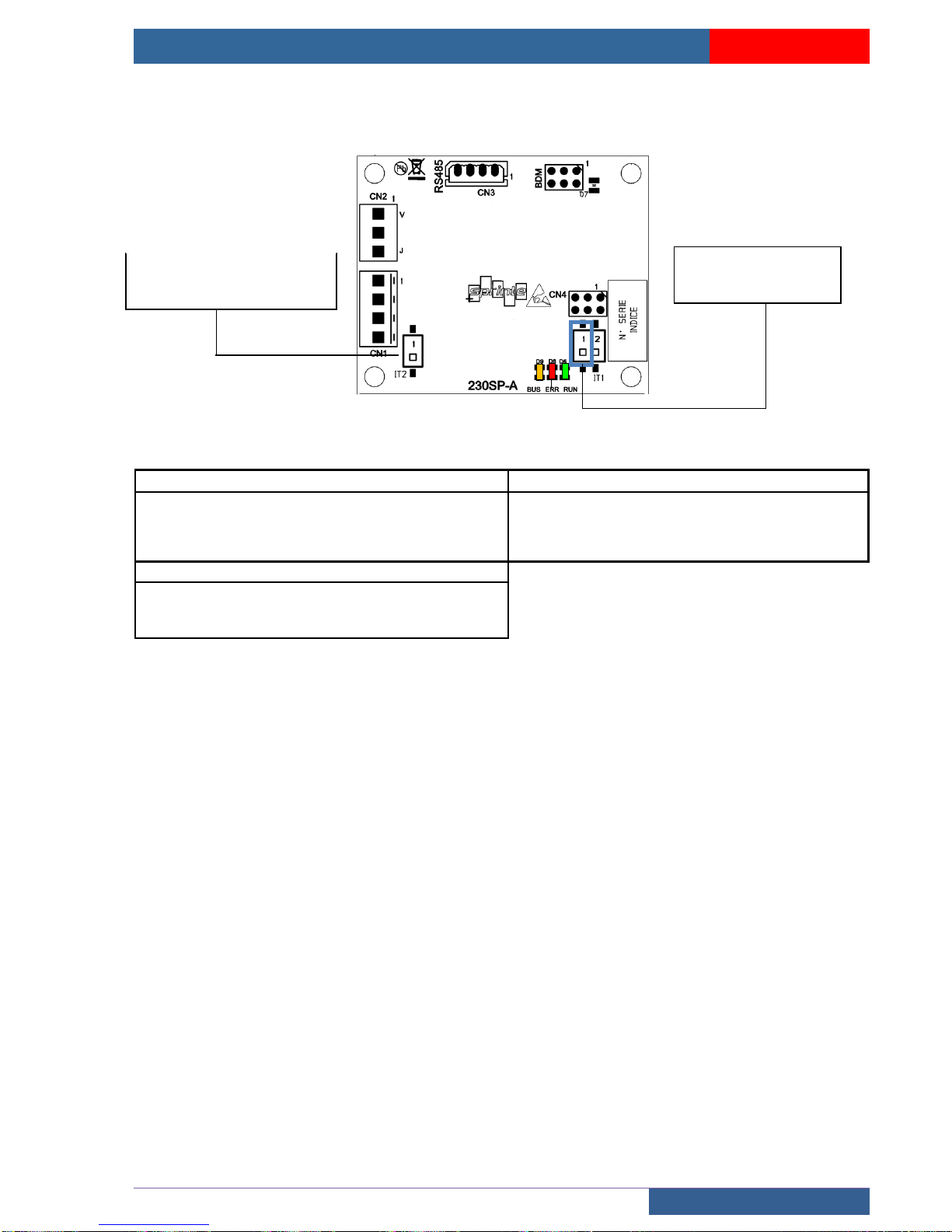
USER MANUAL « ASP 116 EVOLUTION »
BOARDS
Sprinte SAS, All rights reserved, including translation rights
94
5.2.5 230SP Bluetooth board
CN1 BUS CAN input
CN3 RS485
>1
24 V
>1
V24
>2
CANH
>2 A >3
CANL
>3 B >4
GND
>4
GND
CN2 input LED telealarm
>V
input green LED
>CO
common
>J
input yellow LED
IT1 1 =OFF (board 1)
IT1 1 =ON (board 2)
IT2 =OFF (without resistor)
IT1 =ON (with resistor)
BusCAN termination
Page 95
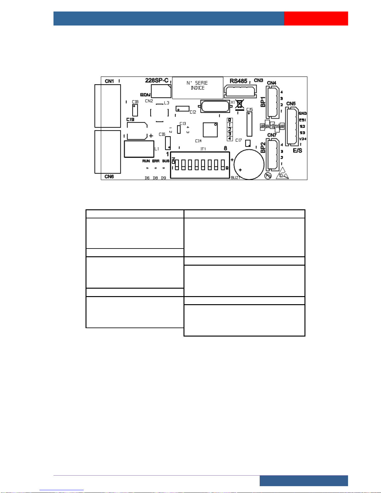
USER MANUAL « ASP 116 EVOLUTION »
BOARDS
Sprinte SAS, All rights reserved, including translation rights
95
5.3 Landing electronics boards
5.3.1 228SP landing board
CN1 CANBus input
CN5 Display
>1
24 V DC
<1
24 VDC
>2
CANBUS 0 HIGH
>2
S3
>3
CANBUS 0 LOW
>3
S2
>4
GND
>4
S1/E1
CN3 RS485
<5
GND
<1
24 V DC
CN6 CANBus output
>2
485H
<1
24 V
>3
485L
<2
CANBUS 0 HIGH
<4
GND
<3
CANBUS 0 LOW
CN4 landing button 1
<4
GND
<1
24V DC
CN7 landing button 2
<2
BP1
<1
24V DC
>3
LED
<2
BP2
<4
GND
>3
LED
<4
GND
Page 96
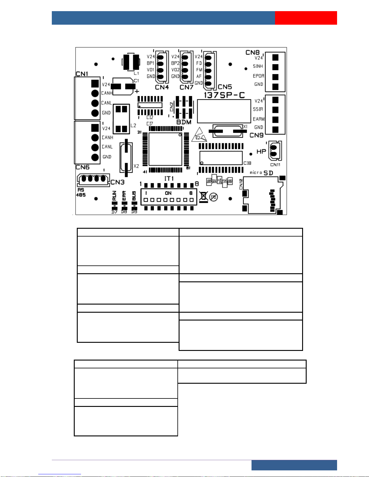
USER MANUAL « ASP 116 EVOLUTION »
BOARDS
Sprinte SAS, All rights reserved, including translation rights
96
5.3.2 137SP landing board with voice synthesizer
CN1 CANBus input
CN5 Display
>1
24 V DC
<1
24 V DC
>2
CANBUS 0 HIGH
>2
S3
>3
CANBUS 0 LOW
>3
S2
>4
GND
>4
S1
CN3 RS485
<5
GND
<1
24 V DC
CN6 CANBus output
>2
485H
<1
24 V
>3
485L
<2
CANBUS 0 HIGH
4
GND
<3
CANBUS 0 LOW
CN4 landing button 1
<4
GND
<1
24V DC
CN7 landing button 2
<2
BP1
<1
24V DC
>3
LED
<2
BP2
<4
GND
>3
LED
<4
GND
CN8 Landing door
CN11 Speaker
<24 V
24 V DC
GND
HP
<SINH
Blocking door
<HP
HP
>EPOR
Landing door state
<GND
GND
CN9 Door alarm
<24 V
24 V
<SSIR
Alarm output
>EARM
rearmament
<GND
GND
Page 97

USER MANUAL « ASP 116 EVOLUTION »
Sprinte SAS, All rights reserved, including translation rights
97
 Loading...