

Page 1

REV LOW
Engineering Manual
___________________________
Spring Air Systems Inc., Oakville, Ontario
Phone (905) 338-2999, Fax (905) 338-0179, info@springairsystems.com
www.springairsystems.com
Page 2
REV LOW
Engineering Manual
Table of Contents
Introduction 1
Operation 2
Variflow Baffles 3
Model Number Designation 4
Water Wash
Hood and Damper Assemblies 8
Dry
REV LOW
REV LOW
Exhaust Duct Sizes 17
Make Up Air 18
REV LOW
REV LOW
REV LOW
May05
REV LOW
Exhaust Calculations
Systems
Controllers
Work Sheet
5
13
14
19
22
23
Page 3

REV LOW Engineering Manual
Introduction
The Revlow hood is a revolutionary idea in commercial kitchen ventilator design. Revlow allows
the exhaust flow to be field adjusted over each appliance without affecting the overall efficiency of
the grease extractor. Your kitchen will exhaust the lowest minimum required to ventilate the
appliances located under the hood. After your kitchen is complete, appliances can be relocated,
added, or removed from under the hood! It’s a simple adjustment to fine-tune your ventilator to
provide excellent smoke capture with maximum grease extraction.
What is a REV LOW hood?
The REV LOW hood is available in two types; a water wash and dry grease extractor. The water
wash hood is automatically cleaned in place at the end of each cooking day. The REV LOW dry
extractor is manually cleaned the dry extractor has inserts that are removed daily and washed in
your dishwasher or pot sink.
The Spring Air Systems REV LOW hood is fabricated from stainless steel with No. 4 finish on all
exposed surfaces. All edges are ground and polished. All hoods are manufactured to stringent
quality standards and are guaranteed to enhance the appearance of any commercial kitchen.
Why REV LOW ?
REV-LOW VALUABLE FUEL DOLLAR SAVINGS:
minimizes the total exhaust by adjusting the
hood to suit individual appliances.
REV-LOW CLEANER DUCTWORK:
maximizes your extraction at all exhaust airflows to
capture more grease in hood. It’s not a filter hood!
REV-LOW FLEXIBILITY:
add, remove or move appliances anytime. VARIFLOW
baffles are easily adjusted without special tools to
balance any cooking bank.
REV-LOW MULTIPLE HOOD BALANCING:
Multiple hoods connected to a single exhaust fan can
be easily balanced.
______________________________________________________________________
_
Spring Air Systems REV LOW Engineering Manual Revision 2.0 -021902
REV LOW
1
Page 4
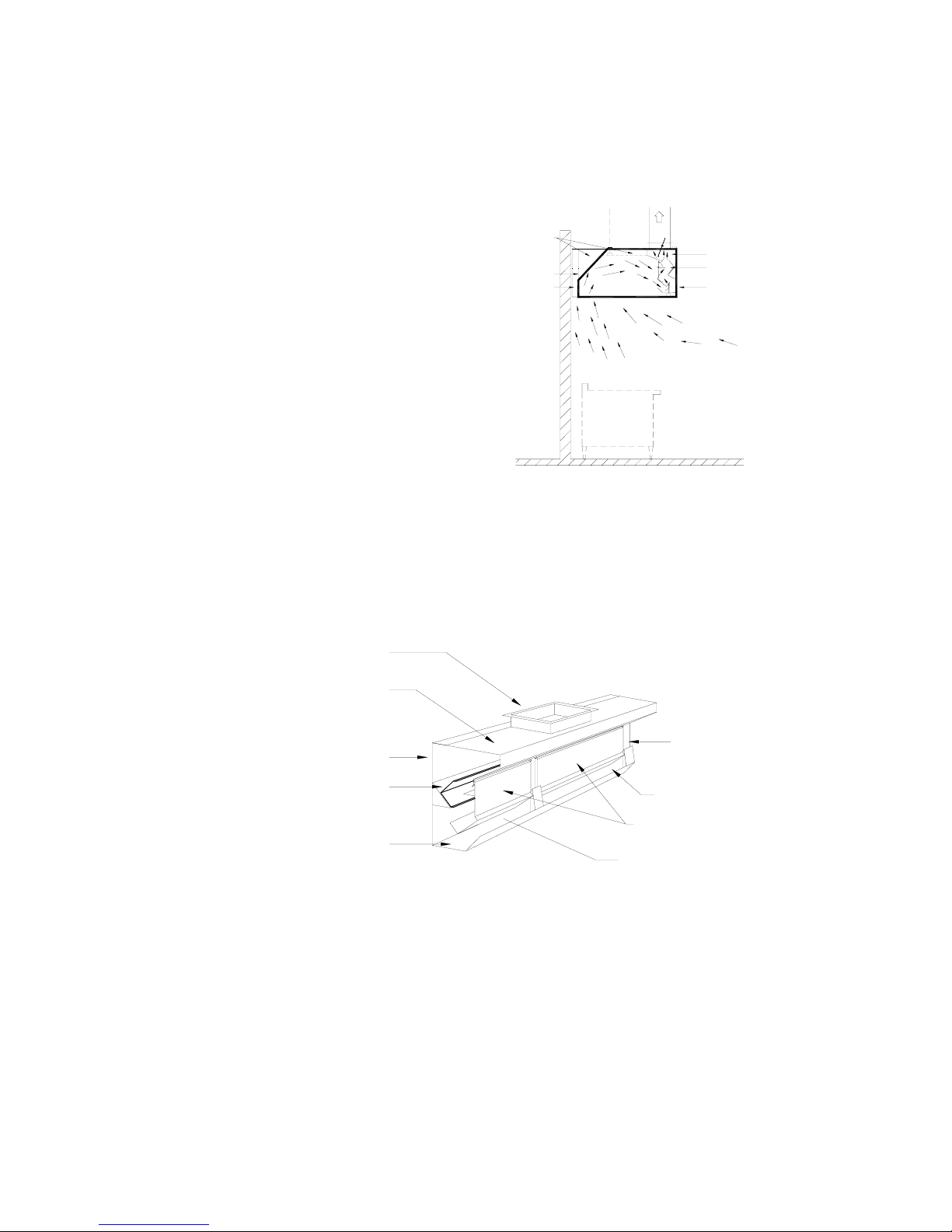
Operation
A commercial kitchen cooking line consists of many different appliances depending on the type of
restaurant or institution. In every commercial kitchen the cooking vapours, which comprise of
grease, smoke, and products of
combustion rise off the cooking surface.
Natural convection forces drive the
cooking vapours up towards the back wall
Roof of hood
as shown in figure 1 below. The kitchen
dilution air is entrained into the cooking
vapours and the air mixture generally
Back wall of hood
Optional 3" aiir space
follows the profile of the back and top of
the hood. The mixture of grease, smoke,
products of combustion, lint, dirt and
kitchen dilution air proceed along the roof
Vapours from appliances
of the hood and follow a path down
towards the core extractor slot (the core
extractor slot extends along the length of
APPLIANCES
the hood). Most of the air mixture enters
the slot and a small amount rolls back into
the hood canopy to meet the main air
stream again.
The REV LOW Hood Model DD-B-F
Figure 1
Optimizing the amount of air mixture that enters the core extractor slot is the key to the REV LOW
system. The REV LOW hood must incrementally maximumize the amount of the air mixture that
enters the slot and minimize the amount of roll back into the canopy as the total amount of the air
mixture deviates along the length of the cooking lineup.
Exhaust Air
Core Extractor
Variflow baffle
Front of hood
Kitchen dilution air
Exhaust duct collar
Top of core extractor
End mullion
Front of core extractor
Variflow Baffle
Shown in full open position
Core extractor slot
Removable Inserts
Grease trough
Core extractor slot
Section View of Core Extractor for DD-B-F REV LOW Hood
Figure 2
The REV LOW accomplishes this complicated process with a unique core extractor profile that
contains a series of specially designed VARIFLOW baffles located along length of the core
extractor. See Figure 2 above. The VARIFLOW baffles are adjusted prior to shipment to allow the
optimum amount of the air mixture to enter the core extractor slot and thereby minimize roll back
into the hood canopy. For instance the VARIFLOW baffles located above a charbroiler are
opened to the maximum 450 CFM/ft position and the VARIFLOW baffles located above ovens or
steamers are closed to the minimum 100 CFM/ft position. This variable adjustment along the
length of each hood provides an exhaust system that truly minimizes the amount of exhaust air to
properly ventilate any kitchen line up.
______________________________________________________________________
2
Spring Air Systems REV LOW Engineering Manual Revision 2.0 -021902
_
Page 5

VARIFLOW Baffles
The most important component for the successful operation of a REV LOW hood is the core
extractor that contains the VARIFLOW baffles. The core extractor profile has been designed to
facilitate the smooth flow of cooking vapours and dilution air from the roof of the hood, down
along the front of the core extractor and into the core extractor slot. The VARIFLOW baffles are
located inside the core extractor along the entire length. The VARIFLOW baffles are adjustable
to provide between a 100 CFM/ft to 450 CFM/ft flow rate into the core extractor slot. The
VARIFLOW baffles are adjustable without any special tools by lifting off the core extractor
removable insert and hand adjusting the position of the baffle. Just set the position of the
VARIFLOW baffle to match the appliance located below. See Figure 3 for isometric view of
Roof of hood
Back of hood
Baffle Closed Baffle OpenedBaffle Partially Closed
Exhaust duct collar
Core extractor
Variflow Baffle
Front of hood
Drain connection
VARIFLOW baffles.
Section View of REV LOW Water Wash Hood with Detail of Variflow Baffle
Figure 3
Benefits
A Spring Air Systems Inc. REV LOW Hood system provides numerous benefits to the
owners/operator of a commercial or institutional restaurant.
1. More comfortable kitchen environment.
2. Lower annual heating cost with little or no capital cost increase.
3. Lower annual air conditioning costs and possible reduced capital cost for air conditioning
equipment.
More Comfortable Kitchen Environment
The Spring Air REV LOW Hood System provides excellent smoke capture using the absolute
minimum net exhaust air from the restaurant. The system can be interlocked with the kitchen
makeup air unit and the building air conditioning units to energize the economizers and provide a
balanced supply and exhaust system. Reduced drafts will provide more comfortable
temperatures throughout the kitchen.
Low Heating Costs
The Spring Air REV LOW Hood System is designed to minimize the net exhaust air from the
building. Less net exhaust means less heating of fresh air or supply air into the building.
Lower Air Conditioning Costs
The Spring Air REV LOW Hood System is designed to minimize the amount of conditioned supply
air required in the store. By reducing the conditioned air into the store, the required air
conditioning load is reduced and the air conditioning operating cost will consequently decrease.
______________________________________________________________________
Spring Air Systems REV LOW Engineering Manual Revision 2.0 -021902
3
_
Page 6
Model Number Designation
The Spring Air Systems REV LOW Hood is available in three basic types
1. Continuous cold water spray/hot water wash - “C”
2. Hot water wash - “H”
3. Dry Ventilator - “D”
Each type of hood provides varying degrees of grease extraction efficiency, automatic/manual
wash, and exhaust fire dampers. For a more detailed description of the types of hood exhaust fire
dampers and wash systems refer to the Spring Air Systems “Ventilator Engineering Manual”.
Model No. Description
DD-B-F Single row box canopy, dry extractor with fusible link dead weight fire damper
CD-B-F Single row box canopy, continuous cold water spray/hot water wash ventilator with fusible
CF-B-F Single row box canopy, continuous cold water spray/hot water wash ventilator with fusible
CT-B-F Single row box canopy, continuous cold water spray/hot water wash ventilator with
HD-B-F Single row box canopy, hot water wash ventilator with fusible link dead weight fire damper
HF-B-F Single row box canopy, hot water wash ventilator with fusible link spring loaded fire damper
HT-B-F Single row box canopy, hot water wash ventilator with thermostatic activated spring loaded
DD-BI Island box canopy, dry extractor with fusible link dead weight fire damper, installed back to
CD-BI Island box canopy, continuous cold water spray/hot water wash ventilator with fusible link
CF-B-FI Island box canopy, continuous cold water spray/hot water wash ventilator with fusible link
CT-B-FI Island box canopy, continuous cold water spray/hot water wash ventilator with thermostatic
HD-BI Island box canopy, hot water wash ventilator with fusible link dead weight fire damper,
HF-B-FI Island box canopy, hot water wash ventilator with fusible link spring loaded fire damper,
HT-B-FI Island box canopy, hot water wash ventilator with thermostatic activated spring loaded fire
link dead weight fire damper
link spring loaded fire damper
thermostatic activated spring loaded fire damper
fire damper
back with another Rev-Low hood
dead weight fire damper, installed back to back with another Rev-Low hood
spring loaded fire damper, installed back to back with another Rev-Low hood
activated spring loaded fire damper, installed back to back with another Rev-Low hood
installed back to back with another Rev-Low hood
installed back to back with another Rev-Low hood
damper, installed back to back with another Rev-Low hood
Chart No. 1
Typical Water Wash Application Single Row Wall Mounted REV LOW
______________________________________________________________________
4
Spring Air Systems REV LOW Engineering Manual Revision 2.0 -021902
Model HD-B-F
Figure 4a
_
Page 7
Typical Water Wash Application Island REV LOW
Two Model HD-BI
Figure 4b
The type “H” and “C” ventilators require a water wash control panel. Consult the “Ventilator
Engineering Manual” or individual water wash panel specification sheets for the proper water
wash control panel. The water wash control panel is supplied to provide operation of the exhaust
fan, supply unit (Spring Air SFA series), time wash cycle, and fire suppression system.
Water Wash REV LOW Hoods
Automatic Wash: Type “C” and “H:” Ventilators
SPRING AIR SYSTEMS ventilators are available with either automatic or manual wash systems.
All water wash ventilators must be interconnected with a water wash control panel.
The “C” and “H” ventilators have incorporated a water wash manifold into the high efficiency
extractor. Spray nozzles are spaced evenly along the wash manifolds. The hot detergent-water
NOZZLE TO WASH EXHAUST
HOT WATER INLET
DUCT AND FIRE DAMPER
TOP OF GREASE EXTRACTOR
TOP OF HOOD
FRONT VIEW OF MANIFOLD
______________________________________________________________________
Spring Air Systems REV LOW Engineering Manual Revision 2.0 -021902
Water wash Manifold
Figure 5
_
END OF
GREASE
EXTRACTOR
SECTION VIEW
5
Page 8
mixture enters the hot water inlet pipe, and travels into the interconnecting pipe to the MANIFOLD
E. The water detergent mixture is sprayed uniformly within the interior of the extractor.
The water/detergent mixture washes the grease, lint and dirt into the
sloping VORTEX BAFFLE that carries the mixture to the end of the
ventilator and into the grease trough.
The mixture travels along the grease trough to the drain. The drain
may be located at either end of the ventilator. Multiple ventilators
may have individual drains factory manifolds to one common drain.
The wash time is adjustable from 0 to 10 minutes. The type “C” is
normally set at 2 minutes while the type “H” is set at 3 minutes.
Depending on the type of cooking equipment the type “C” usually
requires less hot water wash time because of the continuous coldwater spray. During fan and cooking operation, the spray
continuously carries grease, dirt and lint down the drain, which
reduces the daily grease build-up.
The hot water required is approximately .9 gpm/ft. of ventilator at 40
psig (see Chart No.2). The cold-water continuous spray requires
approximately 1.0 gph/ft. of ventilator at 15 psig (see Chart No.3)
Type “C” and “H” Wash
Figure 6
Hot Water Flow Required Model
Ventilator
Length
ft mm @ 40 psi @ 60 psi @ 2.76Kpa @413 Kpa
3.0 914 2.4 2.8 0.14 0.17
3.5 1067 3.1 3.8 0.19 0.23
4.0 1279 3.1 3.8 0.19 0.23
4.5 1372 3.1 3.8 0.19 0.23
5.0 1524 3.1 3.8 0.19 0.23
5.5 1676 3.7 4.5 0.22 0.27
6.0 1829 3.7 4.5 0.22 0.27
6.5 1981 4.3 5.3 0.26 0.32
7.0 2131 4.3 5.3 0.26 0.32
7.5 2286 4.9 6.0 0.30 0.36
8.0 2438 4.9 6.0 0.30 0.36
8.5 2591 5.5 6.7 0.33 0.41
9.0 2743 5.5 6.7 0.33 0.41
9.5 2896 6.7 8.2 0.41 0.50
10.0 3048 6.7 8.2 0.41 0.50
10.5 3200 7.3 8.9 0.44 0.54
11.0 3353 7.3 8.9 0.44 0.54
11.5 3505 7.9 9.7 0.48 0.59
12.0 3658 7.9 9.7 0.48 0.59
12.5 3810 8.5 10.4 0.52 0.63
13.0 3962 8.5 10.4 0.56 0.63
13.5 4115 9.2 11.3 0.56 0.69
14.0. 4207 9.2 11.3 0.56 0.69
14.5 4420 9.8 12.0 0.60 0.73
15.0 4772 9.8 12.0 0.60 0.73
Hot Water Flow
USGPM
Hot Water Flow
USGPM
Hot Water Flow
l/s
Hot Water Flow
l/s
Chart No.2
______________________________________________________________________
6
Spring Air Systems REV LOW Engineering Manual Revision 2.0 -021902
_
Page 9

Cold Water Flow Required Model B
Ventilator
Length
feet mm @ 20 psi @ 138 Kpa feet mm @ 20 psi @ 138 Kpa
3.0 914 0.35 0.02 9.5 2896 0.91 0.05
3.5 1067 0.35 0.02 10.0 3048 0.98 0.06
4.0 1279 0.42 0.02 10.5 3200 1.05 0.06
4.5 1372 0.49 0.03 11.0 3353 1.05 0.06
5.0 1524 0.49 0.03 11.5 3505 1.12 0.07
5.5 1676 0.56 0.03 12.0 3658 1.19 0.07
6.0 1829 0.63 0.04 12.5 3810 1.19 0.07
6.5 1981 0.63 0.04 13.0 3962 1.26 0.08
7.0 2131 0.70 0.04 13.5 4115 1.33 0.08
7.5 2286 0.77 0.05 14.0. 4207 1.33 0.08
8.0 2438 0.77 0.05 14.5 4420 1.40 0.08
8.5 2591 0.84 0.05 15.0 4772 1.47 0.09
9.0 2743 0.91 0.05
Cold
Water
Flow
USGPM
Cold
Water
Flow
l/s
Ventilator
Length
Cold
Water
Flow
USGPM
Cold
Water
Flow
l/s
Chart No. 3
NOTES:
a) All types “C” and “H” water wash ventilators have 3/4” (19 mm) hot water connections.
b) Hot water pressure required is 40 to 60 psi (276 to 413 Kpa).
c) Hot water temperature required is 120F to 180F (49 to 82C).
d) All type “C” ventilators have 1/2” (13 mm) cold water inlet connection.
e) All drain connections are 2” (52 mm) diameter and recommended piped to an open hub drain.
Water Wash
TYPE “C” Core Extractors - Water Wash
The SPRING AIR SYSTEMS type “C” core extractor has the highest grease extraction efficiency
available in a water wash ventilator.
Type “C” Extractor
Figure 7
The cold-water spray extends from the entrance to the exit of the VORTEX CHAMBER B, which
provides a secondary coverage as the exhaust air enters the secondary grease extraction
chamber. The exhaust air continues into the secondary extraction chamber, which contains an
additional baffle, F. Residual grease is deposited on the secondary baffle as the exhaust air
REV LOW Hoods
The contaminated exhaust air enters the extractor slot A and flows
through a transition zone to the VORTEX CHAMBER B. The coldwater spray manifold D sprays a fine cold-water mist into the path
of the exhaust air. The cold-water spray causes the grease
particles to cool, congeal and coagulate forming larger grease
globules. The larger heavier globules are more readily removed
through centrifugal force as the exhaust air accelerates through a
complete 270-degree turn around the VORTEX BAFFLE C. The
grease, dirt and lint are deposited on the VARIFLOW BAFFLE G
and the VORTEX BAFFLE C. The VARIFLOW BAFFLE D is also
adjustable along the length of the grease extractor to provide
varying exhaust airflows. The sloping VORTEX BAFFLE C drains
the collected grease to the end of the ventilator into a grease
trough.
______________________________________________________________________
Spring Air Systems REV LOW Engineering Manual Revision 2.0 -021902
7
_
Page 10

gyrates through the secondary chamber. After leaving the secondary chamber the exhaust air
enters the ventilator fire damper and duct collar and discharges into the ductwork.
TYPE “H” Core Extractors - Water Wash
The SPRING AIR SYSTEMS type “H” core extractor is a high efficiency water wash grease
extractor.
The contaminated air enters the extractor slot A and flows through
the transition zone to the VORTEX CHAMBER B. The exhaust air
accelerates through a complete 270-degree turn around the
VORTEX BAFFLE C. Centrifugal force causes the grease, dirt and
lint particles to deposit on the PRIMARY VARIABLE FLOW
BAFFLE G and the VORTEX BAFFLE C. The VARIFLOW BAFFLE
D adjustable for varying exhaust flows along the length of the
extractor. The sloping VORTEX BAFFLE C drains the collected
liquid grease to the end of the ventilator and into the grease trough.
The exhaust air continues into the secondary extraction chamber,
which contains an additional baffle, F. Residual grease is
deposited on the secondary baffle as the exhaust air gyrates
through the secondary chamber. After leaving the secondary
chamber the exhaust air enters the ventilator fire damper and duct
collar and discharges into the exhaust ductwork.
Type “H” Extractor
Figure 8
Hood and Damper Assemblies
THE SURFACE FIRE SUPPRESSION SYSTEM is always installed in commercial kitchens.
They are required by national and local code. The surface fire suppression system is a wet
chemical or a water sprinkler system. In the event of a fire on the cooking surface electric
thermostat or fusible links activates the system. These systems must be UL/ULC listed.
NOTE: The exhaust fan should remain on after a surface fire suppression system has activated.
A properly designed hood and damper assembly is UL/ULC listed to impede the spread of fire
from the kitchen hood into the exhaust duct. The UL/ULC listed hood and damper assembly is
an important part of the kitchen ventilation system.
SPRING AIR SYSTEMS has three (3) arrangements of hood and damper assemblies available,
arrangement “T”, “F”, and “D”, thermostatic or fusible link activated systems respectively.
Arrangement “T” : Thermostat Activated
The arrangement “T” hood and fire damper assembly consists of a thermostatically activated
spring loaded fire damper electrically connected to the water wash control panel by three wires.
______________________________________________________________________
8
Spring Air Systems REV LOW Engineering Manual Revision 2.0 -021902
_
Page 11

DAMPER RESET
HANDLE
END VIEW
SOLENOID
SOLENOID PIN
DAMPER RETAINING
CLIP
PIN BACK BACK STOP
DAMPER ROD
TERMINAL BLOCKS
DAMPER RETAINING
CLIP - DOWN
POSITION.
DAMPER CLOSURE
SPRING
FIRE DAMPER PIN
(DAMPER OPEN POSITION)
SIDE VIEW DAMPER OPEN POSITION
BX CONDUIT
TO J-BOX
ON TOP OF
VENTILATOR
SPRING
RETAINING
POST
DAMPER RETAINING CLIP
IN UP POSITION
SIDE VIEW DAMPER CLOSED POSITION
SOLENOID IN ENERGIZED POSITION
80 DEGREE PIN
ROTATION TO DAMPER
CLOSED POSITION.
FIRE DAMPER PIN
(DAMPER CLOSED POSITION)
TERMINAL
BLOCK
DAMPER
CLOSURE
SPRING
ACCESS DOOR LOCATION FOR DAMPER RESET
DAMPER RESET
HANDLE
DUCT COLLAR
ACCESS DOOR FOR DA MPER RESET ON
MODELS CT-B-F & HT-B-F
12 in X 18 in .
TOP OF THE
VENTILATOR
THERMOSTAT J-BOX
FIRE DAMPER RESET HANDLE
DAMPER OPEN POSITION.
FIRE DAMPER RESET HANDLE
DAMPER CLOSED POSITION.
SIDE VIEW RESET HANDLE POSITIONS
Arrangement “T” Fire Damper SOE Enclosure
Figure 9
1
FENWALL DETECTOR
2
DAMPER SOLENOID
4
ARRANGEMENT "T" FIRE DAMPER:
E
THREE (3) WIRES TO EACH SOE ENCLOSURE LOCATED
AT EACH EXHAUST DUCT COLLAR ON EVERY HOOD
O
120V/1/60 - 3 AMPS - WIRE EACH SOE IN PARALLEL.
S
“T” Electrical Wiring at SOE Enclosure
Figure 10
______________________________________________________________________
Spring Air Systems REV LOW Engineering Manual Revision 2.0 -021902
9
_
Page 12

In the event of a fire within the core extractor the thermostat will
activate at 360F (182C). The thermostat energizes a solenoid,
which pulls the fire damper pin releasing the fire damper. The
spring loaded fire damper closes tight against the blade stops.
As the fire damper shuts an electric signal is sent to the water
wash control panel. Once the signal reaches the water wash
control panel the exhaust fan shuts off, shunt trip contacts
close, and the hot water solenoid valve energizes to flood the
interior of the grease extractor. The hot water spray and closed
fire damper provide an effective fire barrier to impede the
spread of fire into the exhaust ductwork.
After the fire has been extinguished, rotating a lever on the
outside of the SOE, FIRE DAMPER JUNCTION BOX, manually
resets the fire damper.
Arrangement “T” & “F” Activated
Figure 11
The arrangement “T” has three advantages:
1. The damper is spring loaded to provide a positive closure and seal when closed.
2. The thermostat set at 360F (182C) responds quickly to activate the spring in the event of a
fire.
3. Pushing the fire test button in the control panel can periodically test the fire damper. The
damper will activate as if in a fire condition and can be manually reset.
Arrangement “F”: Fusible Link Activated, Spring Loaded.
The arrangement “F” hood and fire damper assembly consists of a fusible link fire damper and a
damper end switch interlocked electrically to the water wash control panel with two wires.
In the event of a fire within the core extractors, the fusible link melts, closing the fire damper
against the force of a spring. When the fire damper completely closes, the microswitch is
activated and an electrical signal is sent to the water wash control panel.
MICRO SWITCH
MICRO SWITCH
FIRE DAMPER PIN
10
END VIEW
______________________________________________________________________
SUPPORT BRACKET
FIRE DAMPER PIN
BACK STOP
DAMPER ROD
Spring Air Systems REV LOW Engineering Manual Revision 2.0 -021902
MICRO SWITCH N/0 POSITION
WHEN DAMPER OPEN
FIRE DAMPER
CLOSURE SPRING
FIRE DAMPER PIN
(DAMPER OPEN)
SIDE VIEW DAMPER OPEN POSITION
TERMINAL BLOCK
BX CONDUIT
TO J-BOX
ON TOP OF
VENTILATOR
SPRING
RETAINING
POST
Arrangement “F” Fire Damper
Figure 12
_
MICRO SWITCH N/C POSITION
WHEN DAMPER CLOSED
80 DEGREE PIN
ROTATION TO
DAMPER CLOSED
POSITION.
FIRE DAMPER PIN
(DAMPER CLOSED)
SIDE VIEW DAMPER CLOSED POSITION
FIRE DAMPER
CLOSURE SPRING
TERMINAL
BLOCK
ENCLOSURE
Page 13

When the signal reaches the control panel the exhaust fan is shut off, the building fire alarm
contact close and the hot water solenoid valve is energized, flooding the interior of the grease
extractor with water. The water spray and closed fire damper provide an effective barrier to
impede the spread of fire into the exhaust ductwork.
After the fire has been extinguished, the fire damper must be reset. Open the front access door
of the grease extractor and replace the fusible link.
1
DAMPER END SWITCH
2
Arrangement “F” Fire Damper ENS Enclosure
Figure 13
ARRANGEMENT "F" FIRE DAMPERS:
S
TWO (2) WIRES TO EACH ENS ENCLOSURE LOCATED
AT EACH EXHAUST DUCT COLLAR ON EVERY HOOD
N
120V/1/60 - 1 AMPS. WIRE EACH ENS IN PARALLEL.
E
Arrangement “D”: Fusible Link Activated, Dead Weight.
The arrangement “D” hood and damper assembly system consists of a fusible link damper
mounted in the exhaust duct collar.
In the event of a fire within the grease extractor the fusible link melts closing the fire damper
against the force of a dead weight mounted on the damper blade. The closed damper impedes
the spread of fire into the exhaust ductwork. After the fire has been extinguished the fire damper
must be reset. To reset the fire damper the fusible link is replaced. Open the access door on the
front of the ventilator. Pull the fire damper open and replace the fusible link to secure the damper
in place. The fusible link should be examined periodically in accordance with the NFPA-96
(SPRING AIR SYSTEMS recommends inspection every six months.)
______________________________________________________________________
Spring Air Systems REV LOW Engineering Manual Revision 2.0 -021902
Arrangement “D” Fire Damper cross Section
Figure 13B
11
_
Page 14

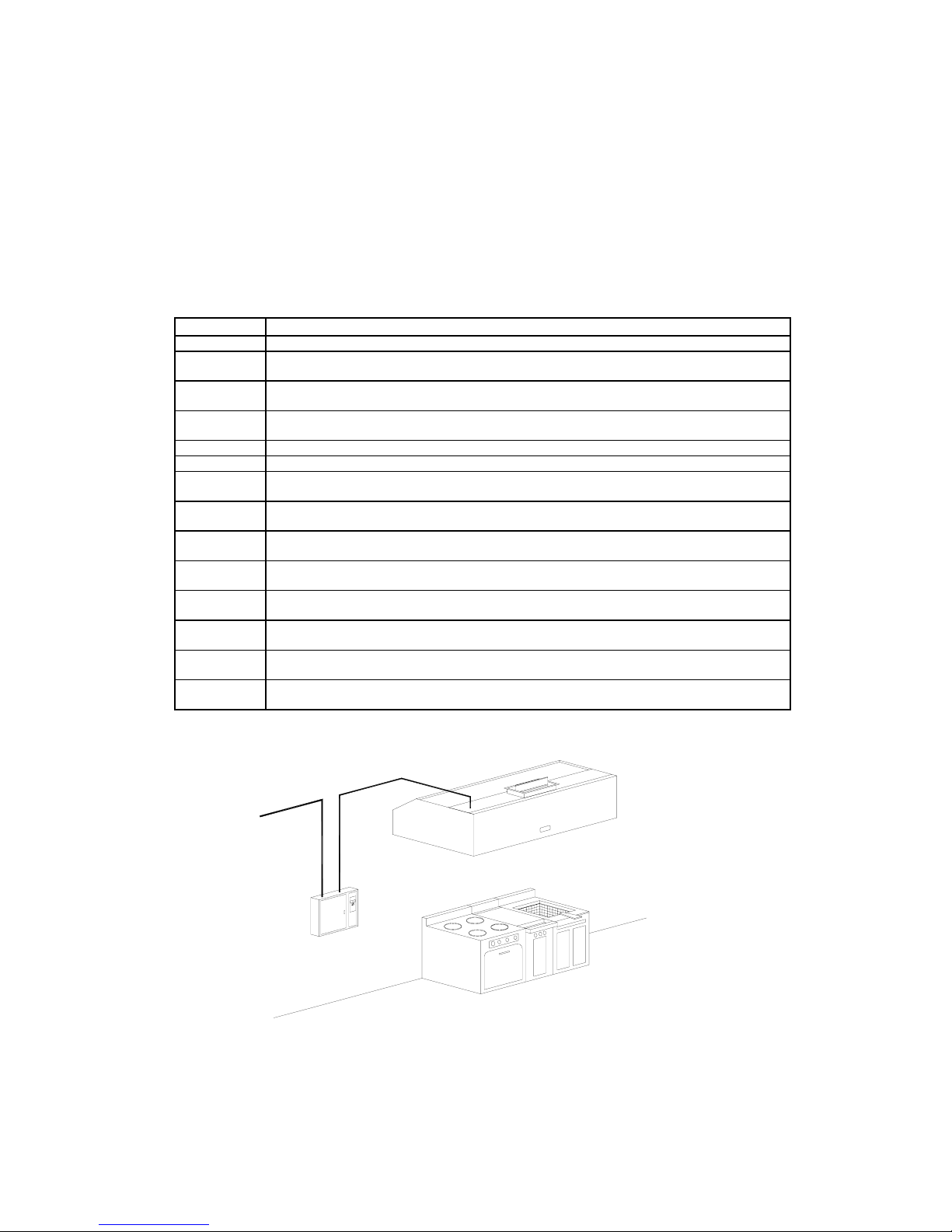
EXHAUST FAN
BY OTHERS
4
5
EXHAUST UNIT
MOTOR STARTER
BY OTHERS
3
7
8
9
WATER WASH REV-LOW HOOD
MODEL CD-B-F-6.0/4.0
1
2
N O T E S :
19mm HOT WATER INLET - 0.8 l/s @2.8 kg/cm2
1.
BACKFLOW PREVENTOR SUPPLIED AND INSTALLED
2.
6
BY MECHANICAL CONTRACTOR
3.
19mm HOT WATER LINE TO EACH VENTILATOR SECTION.
4.
POWER SUPPLY TO EXHAUST FAN MOTOR STARTER
(BY OTHERS)
5.
POWER FROM EXHAUST FAN MOTOR STARTER TO
EXHAUST FAN DISCONNECT SWITCH - BY OTHERS
6.
INTERLOCK FROM WATER WASH PANEL MODEL SB10H
TO EXHAUST FAN MOTOR STARTER - 120V/1/60, 5 AMPS.
POWER SUPPLY TO WATER WASH PANEL MODEL SB10H
7.
120V/1/60, 15 AMPS., 24 HOURS/DAY
INTERLOCK TO WET CHEMICAL CYLINDER HEAD FROM8.
WATER WASH PANEL - 120V/1/60 - 2 AMPS
51mm DRAIN CONNECTION TO OPEN HUB DRAIN.9.
SPRING
AIR
SYSTEMS
FAN
ON/OFF
WASH
APPLIANCES
WET CHEMICAL
FIRE SUPPRESSION
CYLINDER
Typical Water Wash Rev-Low Schematic
Figure 14
Figure 14 above shows a water wash Rev-low field piping and wiring schematic. The hood is a
HD-B; a hot water wash hood with a dead weight fusible link fire damper. The water wash panel
is mounted about 42” (1067 mm) off the finished floor. A water line from a hot water tank is
connected to the inlet of the water wash panel. An interconnecting water line is piped from the
outlet of the wash panel to the 3/4” (19 mm) inlet of the REV LOW hood. A 2” (52 mm) drain on
the hood is connected to an open hub drain and then to a grease interceptor. The panel is
powered by 120V/1/60 - 15-amp service. Interconnecting wiring includes power to the remote
motor starter, interlock to the wet chemical cylinder head, and optional power to the supply fan
and supply fresh air damper. All control wiring is 120V/1/60.
The water wash hood washes in place at the end of each cooking day. For more detail
information covering the water wash control panels available please refer to the Spring Air
Systems “Ventilator Engineering Manual” or the individual water wash panel specification sheets.
______________________________________________________________________
12
Spring Air Systems REV LOW Engineering Manual Revision 2.0 -021902
_
Page 15

Dry REV LOW Hoods - DD-B-F
Manual Wash: Type “D” Ventilator
The type “D” incorporates a core extractor similar to type
“H” but without the wash manifolds. The type “D” is
recommended for light to medium cooking applications
where grease is minimal.
The liquefied grease collects on internal baffles as
described in the “Grease Extractor” section of the
manual. The baffles are designed to drain the liquefied
grease to the end of the ventilator and into the grease
trough and grease cup.
To clean the grease extractor, the front access door and
grease cup are removed and manually washed in a
kitchen sink.
The two interior baffles and grease trough should be
wiped down with a damp cloth soaked in a water and
mild detergent mixture. If the cooking application
generates high temperatures, the grease trough may
require additional cleaning and/or scraping to remove
baked-on solidified grease.
Type “D” Grease Extractor
Figure 15
TYPE “D” GREASE EXTRACTOR
The SPRING AIR SYSTEMS type “D” core extractor is a high efficiency extractor. The type “D”
core extractor removes grease, dirt and lint through centrifugal force. Removing the front access
door and wiping the interior with a damp cloth manually wash the core extractor chamber.
The contaminated exhaust air enters the slot A and flows through the transition zone to the
VORTEX CHAMBER B. The exhaust air
accelerates through a complete 270degree turn around the VORTEX
BAFFLE C. Centrifugal force causes the
grease, dirt and lint particles to deposit
on the PRIMARY VARIABLE FLOW
BAFFLE G and VORTEX BAFFLE C.
The sloping VORTEX BAFFLE C drains
collected grease to the end of the
ventilator into the grease cup H.
The exhaust air continues into the
secondary extraction chamber, which
contains an additional baffle, F.
Residual grease is deposited on the
secondary baffle as the exhaust air
gyrates through the secondary chamber.
Type “D” Extractor
Figure 16
______________________________________________________________________
_
Spring Air Systems REV LOW Engineering Manual Revision 2.0 -021902
13
Page 16

REV LOW Exhaust Air Calculations
Single Row Wall Mount
The Revlow Hood exhaust air formula is as follows:
Once the cooking line up has been established, the TOTAL EXHAUST (TEX) is calculated by
adding each individual NEV valve.
TEX = (NEV of appliance No. 1 + NEV of appliance No. 2 + NEV of appliance No. 3 +....)
Refer to Chart No. 4 for EXHAUST FLOW RATE (EFR) for the various types of Spring Air
Systems hoods.
The TOTAL EXHAUST (TEX) is determined by adding the NET EXHAUST VOLUME (NEV) CFM
(l/s) for each individual cooking appliance. The NET EXHAUST VOLUME (NEV) for individual
appliances varies depending on the amount of smoke, particulate, and grease generated, the
surface temperature and whether the appliance is gas or electric. Gas appliances require higher
NEV because of the high flue gas temperatures. Chart No. 4 includes typical “NEV” values for
most cooking applications. Consult the factory if an appliance is not listed.
It is important to know the dimensions of each appliance. The NET EXHAUST VOLUME (NEV)
decreases and increases proportionally to the length of some appliances. These appliances are
indicated in Chart No. 4 with length dimensions. For lengths other than indicated prorate the
value in the chart.
WARNING
The REV LOW method is an excellent guide to assist in calculating the TOTAL
EXHAUST (TEX) volumes, but consideration must be made for the conditions
within the kitchen. i.e. location of the hood to doors, windows, and pass through
which might create a draft. Consult the factory when unusual site conditions
exist.
The total exhaust must correspond to the minimum allowable per the Spring Air
Systems UL and ULC listing. Check with factory or go directly to the UL web site
www.ul.com
The complete kitchen ventilation system must be balanced, such that a minimum
of 80% continuous heated makeup air is provided through a dedicated makeup
air system or the kitchen A/C units. It is good engineering practice to provide
this heated fresh air into the kitchen space. The heated fresh air should not
exceed 90 percent of the total exhaust volume.
Determining REV LOW Hood Dimensions
Hood Length:
The hood length should equal the width of all the cooking appliances to be covered by the hood
plus allow and additional 6” (152 mm) overhang on either end of the cooking line up.
______________________________________________________________________
14
_
Spring Air Systems REV LOW Engineering Manual Revision 2.0 -021902
Page 17

Hood Width: Single Row Wall Mounted
The hood width should be equal the depth of the largest appliance from the wall plus allow for an
additional 12” (305 mm) overhang from the front of the appliance. The hood should be a
minimum 47” (1194).
Net Exhaust Air (NEV)Volume Chart for All RevLow hoods
Cooking Appliances Net Exhaust Volume
Description Length (in) Electric CFM Gas CFM
Charbroiler 24 24 900 1125
Charbroiler 30 30 1100 1325
Charbroiler 34 34 1300 1600
Charbroiler 36 36 1440 1800
Charbroiler 48 48 1600 2000
Charbroiler 60 60 1800 2250
Charbroiler 72 72 2250 2800
Chicken broaster 20 20 200 200
Chicken broaster 30 30 300 300
Conveyor Oven one deck 90 90 325 430
Conveyor Oven two deck 90 90 430 575
Combi Oven 51 850 880
Comb. Wood/Gas Brick Oven 48 48 - 1200
Comb. Wood/Gas Brick Oven 48 48 - 1200
Donut Fryer 32 32 285 430
Donut Fryer 72 72 320 480
Fry Top 36 36 300 340
Fryer Pitco model 14 17 - 150
Fryer 15 15 - 190
Fryer 16 16 100 200
Fryer 18 18 125 250
Fryer 24 24 150 300
Griddle 24 24 200 225
Griddle 36 36 250 275
Gyro 18 18 - 175
Hot Top Range 48 48 700 880
Induction Cookers 18 72 n/a
Kettle one with stand 28 28 130 130
Kettle Single 45 45 250 250
Microwave 24 24 30 -
Oven 38 38 180 225
Pasta Cooker 18 18 150 150
Pizza Oven 60 60 260 325
Rotisserie Oven 42 42 550 750
Rotisserie Oven 66 66 960 1250
Range stock pot 24 24 255 300
Range two burner regular duty 12 12 180 225
Range four burner regular duty 24 24 275 315
Range six burner regular duty 36 36 415 475
Salamander Broiler 36 36 270 350
Spreader 12 12 10 10
Steamer 30 30 150 Solid Fuel 36” 36 - 1800
Solid Fuel – 60” 60 - 2400
Tilting Skillet 42 42 370 500
Toaster 18 18 50 50
Wok – one hole 30 30 - 500
Wok – two hole 60 60 - 850
Wok –three hole 90 90 - 1400
Woodstone Oven 64 64 - 400
Upright Broiler 2 shelf 36 36 540 700
Upright Broiler 3 shelf 36 36 810 1050
Warming Lamp 18 18 30 30
Chart No. 4
______________________________________________________________________
Spring Air Systems RevLow Engineering Manual Revision 2.0 -021902
15
_
Page 18

Island REV LOW Hoods
The Island Revlow Hood exhaust air formula is as follows:
Once the cooking line up has been established, the TOTAL EXHAUST (TEX) is calculated by
adding each individual NEV valve.
TEX = (NEV of appliance No. 1 + NEV of appliance No. 2 + NEV of appliance No. 3 +..)x 1.10
Refer to Chart No. 4 for NEV of various appliances.
The TOTAL EXHAUST (TEX) is determined by adding the NET EXHAUST VOLUME (NEV) CFM
(l/s) for each individual cooking appliance and then multiplying by a factor of 1.1. The NET
EXHAUST VOLUME (NEV) for individual appliances varies depending on the amount of smoke,
particulate, and grease generated, the surface temperature and whether the appliance is gas or
electric. Gas appliances require higher NEV because of the high flue gas temperatures. Chart
No.4 includes typical “NEV” values for most cooking applications. Consult the factory if an
appliance is not listed.
It is important to know the dimensions of each appliance. The NET EXHAUST VOLUME (NEV)
decreases and increases proportionally to the length of some appliances. These appliances are
indicated in Chart No. 4 with length dimensions. For lengths other than indicated prorate the
value in the chart.
Determining REV LOW Island Hood Dimensions
Hood Length:
The hood length should equal the width of all the cooking appliances to be covered by the hood
plus allow and additional 9” (230 mm) overhang on either end of the cooking line up.
NOTE 3
41.00
(1041)
APPLIANCES
10.00 (254)
3.00 (76)
NOTE 5
NOTE 2
NOTE 2
NOTE 7
NOTES:
EXHAUST DUCT COLLAR WITH 1" (25mm) PERIMETER FLANGE.
1.
MINIMUM WIDT H 54" (13 72mm).
2.
MAXIMUM LENGT H 14'- 0" (426 7mm). FOR GREA TER LENGTH
3.
USE MULTIPLE UNITS.
HANGER ROD BY INSTALLER.
4.
RECOMMENDED MOUNTING HEIGHT 6'6" (1980) FROM FINISHED FLOOR.
5.
6.
TYPICAL HANGER ROD BRACKET LOCATION - 4 SUPPLIED.
7.
DUCT LENGTH TO SUIT EXHAUST VOLUME.
8.
STAINLESS STEEL GREASE CUP.
9.
REMOVEABLE GREASE INSERT.
10.
VARIFLOW BAFFL ES.
PLAN VIEW
NOTE 6
NOTE 4
NOTE 9
NOTE 10
NOTE 8
APPLIANCES
SECTION VIEW
Typical Island REV LOW dimensional drawing model DD-B-F-I
Two Hoods shown Figure 17
______________________________________________________________________
16
_
Spring Air Systems REV LOW Engineering Manual Revision 2.0 -021902
23.00
(584)
3.00(76)
Page 19

Hood Width: Island REV LOW
The hood width should be equal the depth of the largest appliance from the wall plus allow for an
additional 12” (305 mm) overhang from the front of the appliance. Each hood should be a
minimum 54” (1372mm).
REV LOW Exhaust Volume Vs Exhaust Duct Size
Exhaust
Volume
CFM l/s
450 212 10 x 4 254 x 102 3500 1652 10 x 33.5 254 x 851
500 236 10 x 4.5 254 x 114 3625 1711 10 x 34.5 254 x 876
625 295 10 x 6.0 254 x 152 3750 1770 10 x 36.0 254 x 914
750 354 10 x 7.0 254 x 178 3875 1829 10 x 37.0 254 x 940
875 413 10 x 8.0 254 x 203 4000 1888 14 x 27.0 356 x 686
1000 472 10 x 9.5 254 x 241 4125 1947 14 x 28.0 356 x 711
1125 531 10 x 10.5 254 x 267 4250 2006 14 x 29.0 356 x 737
1250 590 10 x 12.0 254 x 305 4375 2065 14 x 30.0 356 x 762
1375 649 10 x 13.0 254 x 330 4500 2124 14 x 30.5 356 x 775
1500 708 10 x 14.0 254 x 356 4625 2183 14 x 31.5 356 x 800
1625 767 10 x 15.5 254 x 394 4750 2242 14 x 32.5 356 x 826
1750 826 10 x 16.5 254 x 419 4875 2301 14 x 33.0 356 x 838
1875 885 10 x 18.0 254 x 457 5000 2360 14 x 34.0 356 x 864
2000 944 10 x 19.0 254 x 483 5125 2419 14 x 35.0 356 x 889
2125 1003 10 x 20. 254 x 508 5250 2475 14 x 36.0 356 x 914
2250 1062 10 x 21.5 254 x 546 5375 2537 14 x 36.5 356 x 927
2375 1121 10 x 22.5 254 x 572 5500 2596 14 x 37.5 356 x 953
2500 1180 10 x 24.0 254 x 610 5625 2655 14 x 38.5 356 x 978
2625 1239 10 x 25.0 254 x 635 5750 2714 14 x 39.0 356 x 991
2750 1298 10 x 26.0 254 x 660 5875 2773 14 x 40.0 356 x 1016
2875 1357 10 x 27.5 254 x 699 6000 2832 14 x 41.0 356 x 1041
3000 1416 10 x 28.5 254 x 724 6125 2891 14 x 42.0 356 x 1067
3125 1475 10 x 30.0 254 x 762 6250 2950 14 x 42.5 356 x 1080
3250 1534 10 x 31.0 254 x 787 6375 3008 16 x 38.0 406 x 965
3375 1593 10 x 32.0 254 x 813 6500 3067 16 x 39.0 406 x 991
1. If exact exhaust volume is not indicated use duct size closest to required exhaust.
2. Model B water wash hoods and dry extractors have 1.5” W.C. (0.38kPa) for exhaust
flow rates from 90 to 450 CFM/ft (140 to 700 l/s/m)
Duct Collar Size Exhaust
Volume
W x L
in x in
W x L
mm x mm
CFM l/s
Chart No. 5
Duct Collar Size
W x L
in x in
W x L
mm x mm
Make Up Air/Supply Air
Introducing fresh air back into the kitchen is generally recommended as good engineering
practice. The amount of make up air should not exceed the total exhaust to maintain a negative
pressure within the kitchen. Inadequate amounts of fresh replacement air will result in cold
drafts, hot spots, poor hood smoke capture and generally uncomfortable working conditions
within the kitchen and uncomfortable environment in the dining room for the customers.
One excellent method of introducing makeup air is through a make up air plenum built into the
ventilator. SPRING AIR SYSTEMS has two optional make up air arrangements; MP and MC.
Directing the make up air through the exhaust hood ensures the correct quantity of make up air
and good air distribution.
______________________________________________________________________
Spring Air Systems REV LOW Engineering Manual Revision 2.0 -021902
17
_
Page 20

MP
Model DD-B-F-MP
Figure 18
MC
Model DD-B-F-MC
Figure 19
The make up air is discharged into the kitchen through
a perforated panel located on the front of the Rev-Low
ventilator. This method provides very low discharge
velocity. The fresh air is heated to 55F (13C). The
total supply is 80% to 90% of the total exhaust air
volume. The make up air plenums have 1/2” foam
insulation on the interior surfaces for sound attention
and insulation. A fire damper is located at the supply
air inlet on top of the ventilator.
The make up air is discharged into the kitchen down
through a perforated panel located on the front of the
Rev-Low ventilator. The fresh air is directed down
toward the floor in front of the cooking appliances.
This method is best suited for warm climates. The
fresh air is tempered to 55F (13C) and between 70%
to 80% of the total exhausts air volume. A fire
damper is located at the supply air inlet on top of the
ventilator.
______________________________________________________________________
18
Spring Air Systems REV LOW Engineering Manual Revision 2.0 -021902
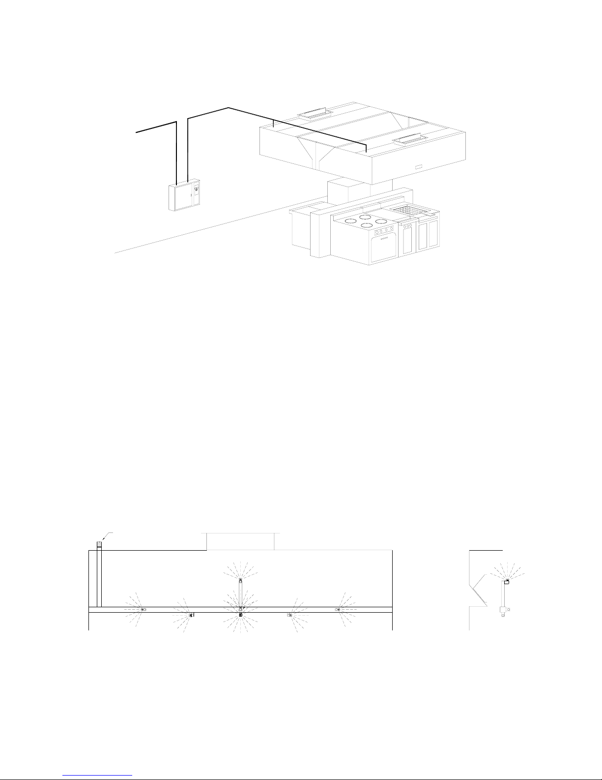
Two Models DD-B-F-I-MC
Figure 20
_
Page 21

The REV LOW System Approach
The Spring Air Systems REV LOW Hood does not work alone. A good commercial kitchen
exhaust fan, supply unit, and hood controller are required.
Spring Air Systems Inc. designs a supply unit especially for the REV LOW hoods; the SFA series.
The SFA is available in a vertical or horizontal arrangement, indoor or outdoor and with integral
gas reheat and remote gas and electric reheat.
SFA-OV Unheated Makeup Air Unit
The SFA-V unit is designed and constructed
specifically for commercial kitchen applications.
The SFA-V is a vertical supply unit that introduces
unheated fresh air directly into a duct-mounted
electric or gas-heating unit. The vertical
arrangement requires minimum roof space. The
roof mounted SFA-V is complete with filters, supply
fan motorized discharge damper and end switch,
fan motor, belts, drives and perimeter curb. Supply
air capacities range from 500 to 8,000 CFM. The
SFA-OV is used in conjunction with a remote indoor
gas fired duct heater or electric heating coil.
SFA-OV
Figure 21
SFA-OH Unheated Makeup Air Unit
The SFA-OH unit is designed and constructed
specifically for commercial kitchen applications.
The SFA-OH is a horizontal supply unit that
introduces unheated fresh air directly into a ductmounted electric or gas-heating unit. The roof
mounted SFA-OH is complete with filters, supply fan
motorized inlet damper and end switch, fan motor,
belts, drives and perimeter curb. Supply air
capacities range from 500 to 8,000 CFM. The SFAOH is used in conjunction with a remote indoor gas
fired duct heater or electric heating coil.
SFA-OH
Figure 22
______________________________________________________________________
Spring Air Systems REV LOW Engineering Manual Revision 2.0 -021902
19
_
Page 22

FRESH AIR UNIT MODEL SFA10-OV
750 CFM @ 0.50" W.C.
C/W 0.25 HP, 120V/1/60 MOTOR
5
10'0" MINIMUM
EF-1 - MODEL PNU135 -RG
C/W 1.0 HP, 120V/1/60 MOTOR
2
EXHAUST FAN
1515 CFM @ 1.75" W.C.
3
1
EXHAUST FAN EF -1
MOTOR STARTER
N O T E S :
POWER SUPPLY TO EXHAUST FAN MOTOR STARTER - 120V/1/60, 8.8 FLA
1.
POWER FROM EXHAUST FAN MOTOR STARTER TO EXHAUST FAN
2.
DISCONNECT SWITCH - 120V/1/60, 8.8 FLA
POWER FROM RPD20 CONTROLLER TO EXHAUST FAN MOTOR
3.
STARTER COIL - 120V/1/60.
POWER SUPPLY TO SFA10-OV MOTOR STARTER - 120V/1/60, 8.8 FLA
4.
POWER FROM SFA10-OV MOTOR STAR TER TO SFA10-OV
5.
DISCONNECT SWITCH - 120V/1/60, 8.8 FLA
POWER FROM RPD20 CONTROLLER TO SFA10-OV MOTOR
6.
STARTER COIL - 120V/1/60.
9.
POWER FROM RPD20 CONTROLLER TO SUPPLY FRESH AIR
SFA10-OV UNIT MOTORIZED DISCHARGE DAMPER 120V/1/60
10.
POWER SUPPLY TO RPD11 CONTROLLER - 120V/1/60, 15 AMPS.
11.
INTERLOCK TO SHUNT TRIP - DRY CONTACT - 5 AMPS. MAX.
(SHUNT TRIP SUPPLIEND BY ELECTRICAL CONTRACTOR)
TO WET CHEMICAL FIRE SUPPRESSION CYLINDER HEAD MICRO SWITCH
12.
120V/1/60, 2 AMPS. - CONNECT TO N/O CONTACT.
POWER SUPPLY TO THE 20 KW ELECTRIC DUCT HEATER - 208V/3/60 - 55 FLA
13.
CONTROL WIRING TO ELECTR IC DUCT HEATER THERMOSTAT
14.
INTERLOCK TO ELECTRIC DUCT HEATER FROM RPD20 CONTROL - 120V/1/60
15.
15
750 CFM FRESH AIR
HEATED TO 70°F
DISCHARGED INTO
THE KITCHEN AREA
ELECTRIC DUCT HEATER
20 KW WITH SCR CONTROL
13
14
WET CHEMICAL
FIRE SUPPRESSION
CYLINDER
9
12
EXHAUST SUPPLY
FAN
OCCUPIED/UNOCCUPIED
SUMMER/WINTER
SUPPLY UNIT MAU-1
MOTOR STARTER
6
4
10
11
MODEL DD-B-F-6.0/3.92
RPD11
REV-LOW
HOOD
CONTROLLER
FAN
APPLIANCES
Typical REV LOW Hood Schematic with electric heating
Figure 23
The kitchen and dining room must be balanced to provide a proper system. The schematic
shows a typical 100% exhaust, with 80% fresh air supplied directly to the kitchen through some
type of heating unit. A electric duct heater as shown above or gas, steam or hot water can
supply this heat. The remaining 20% required to balance the restaurant must be supplied through
the dining room air conditioning unit(s) economizer or through some other makeup air unit. (Such
as a Spring Air Systems SFA-IGO Unit)
SLAB
NFPA-96
ALL WELDED
DUCT
HANGER
RODS
FINISHED CEILING
FINISHED FLOOR
______________________________________________________________________
20
Spring Air Systems REV LOW Engineering Manual Revision 2.0 -021902
_
Page 23

SFA-IGO Heated Makeup Air Unit
General
The SFA-IGO is an indirect, gas-fired
make-up air unit for commercial
applications. The unit is designed to
introduce 100% fresh air into a
commercial building. When the amount of
heated makeup air required exceed the air
conditioning unit capacity use the SFAIGO. The SFA-IGO is roof-mounted on a
perimeter curb or sleeper with optional
turndown plenum. Supply air capacities
range from 500 to 8000 CFM with burners
from 80,000 to 600,000 BTU/hr output.
Typical SFA-IGO
Figure 24
Heating Capacity:
The total heating required is equal to the following:
Heating Capacity (BTU/hr) = Supply Volume (CFM) x 1.09 x (TI - TO)
Where: TI = Supply discharge temperature required (F)
TO = winter design temperature for the area (F)
Use the Chart No. 6 below for selection of burner required.
SFA-IGO BURNER ENGINEERING DATA
HEATER
SIZE
INPUT OUTPUT (IN) (SCFH)
100
150
200
250
300
350
400
(1)
Not available with power vent.
(2)
112,500 BTU/hr with power vent.
(3)
150,000 BTU/hr with power vent.
(4)
All units require the following clearances: Front: 48” Bottom: 0” Sides: 24” Rear: 6”
(1)
100,000
(2)
150,000
200,000
250,000
300,000
350,000
400,000
BTU/HR GAS PIPE
CONNECTION
80,000
120,000
(3)
160,000
187,000
225,000
262,500
300,000
3/4
3/4
3/4
3/4
3/4
3/4
3/4
Chart No. 6
NATURAL
GAS FLOW
100
150
200
250
300
350
400
______________________________________________________________________
Spring Air Systems REV LOW Engineering Manual Revision 2.0 -021902
21
_
Page 24

950 CFM @ 1.75" W.C.
EXHAUST FAN ROOF CURB
EXHAUST DUCT SUPPLIED
AND INSTALLED PER NFPA-96
EXHAUST DUCT ENCLOSURE
FROM BOTTOM OF CURB TO
BELOW ROOF JOIST 24" TYPICAL
EXHAUST FAN
MODEL PNU120-RG
C/W 120V/1/60
3/4 HP MOTOR
24.00
10" DIA FLEX DUCT
10'0" MINIMUM
SPRING AIR SYSTEMS MAKEUP AIR UNIT
MODEL SFA10-IGOD
750 CFM @ 0.50" W.C.
0.33 HP 120V/1/60
10"X 24" DUCT DROP FROM SFA10
EXTERNALLY INSULATED
HANGER RODS
EXHAUST DUCT COLLAR C/W
1" PERIMETER FLANGE AND
ARRANGEMENT "D" FIRE DAMPER
10" X 8" - 950 CFM @ 1.25" W.C.
SPRING AIR SYSTEMS
MODEL DD-B-F 6.0/3.92
APPLIANCES
FINISHED CEILING
24" X 24" DIFFUSER
375 CFM EACH
FROM HEATED MAKEUP
Typical REV LOW Hood Schematic with SFA-IGO
Figure 25
REV LOW Hood Controllers
Spring Air Systems Inc. manufacturers a
REV LOW Hood Controller model RPD-P
(For use with gas or electric duct
heaters) for complete single switch
operating of the exhaust/supply system.
The operator rotates the selector switch
to the occupied position and the exhaust
and supply fans energize, the fresh air
damper opens, and the air conditioning
unit economizers open (optional). In
addition, the panels may be interlocked
10"
SPRING AIR SYSTEMS INC.
MODEL RPD20
EXHAUST SUPPLY
OCCUPIED / UNOCCUPIED
SUMMER/WINTER
to the shunt trip, surface fire suppression
system or building management system.
Spring Air Systems can also supply the
motor starters from stock.
6.5"
4"
RPD11 Controllers
Figure 26
FINISHED FLOOR
MODEL RPD11
EXHAUST SUPPLY
OCCUPIED/UNOCCUPIED
SUMMER/WINTER
______________________________________________________________________
22
Spring Air Systems REV LOW Engineering Manual Revision 2.0 -021902
_
Page 25

Specification
Refer to individual specification sheets for the model and type of REV LOW hood selected. See
Chart No. 1 for a list of the various alternatives available. Refer to the individual specification
sheets for SFA models and REV LOW hood controllers available.
REV LOW Work Sheet
Date Job Name
Representative Job Location
Engineering Food Service
Item
No.
Description of Appliance Gas/
Electric
Length
(in)
NEV*
(CFM)
Totals
*See chart No. 4 in REV LOW Engineering Manual
Hood Length (Total Length above + 12” for single row +18” for Island)
Minimum CFM (100 CFM/ft x length (ft) or total NEV above)
Exhaust Duct Collar (from Chart No. 5 in Engineering Manual)
______________________________________________________________________
Spring Air Systems REV LOW Engineering Manual Revision 2.0 -021902
23
_
Page 26

Other Fine Products From
SPRING AIR SYSTEMS...
• Water Wash Ventilators
♦ Hot Water Wash
♦ Cold Water Spray/Hot Water Wash
♦ Water Wash Control Panels
• Dry Extractor Hoods
• REV-LOW Hoods
• Cartridge Hoods
• Filter Hoods
• Surface Fire Suppression
• Commercial Kitchen Exhaust Fans
• Kitchen Enviro Systems
♦ KES - 100% Exhaust
• Commercial Kitchen Supply Units
• Compensating Hoods
• Exhaust Fans
• Supply Fans
• Commercial Kitchen Control Panels
• Variable Speed Exhaust/Supply Systems
Phone: 905-338-2999, FAX: 905-338-1079, e-mail info@springairsystems.com
www.springairsystems.com
 Loading...