

Spring Air Systems MP10C, MP10H ,MP20C, MP20H,MP30C, MP30H Maintenance Manual
VENTILATOR
MAINTENANCE MANUAL
___________________________
Spring Air Systems Inc., Oakville, Ontario
Phone (905) 338-2999, Fax (905) 338-0179
Ventilator Operating and Maintenance
Manual
Table of Contents
Introduction 1
Model Numbers 2
Water Wash Control Panels 2
Control Panel Operation 3
Single Sequence Wash 3
Two Sequence Wash 4
Three Sequence Wash 5
Four and Five Sequence Wash 6
Remote Piping 7
Cleaning the Exterior 7
Wash Timer Settings 7
Automatic Wash Systems 8
Setting the Automatic Time Clock 9
Grease Extractor Operation: Type “C” 14
Grease Extractor Operation: Type “H” 14
Grease Extractor Operation: Type “D” 15
Ventilator Wash System 15
Hot and Cold Water Requirements 18
Second Line Fire Suppression: Arrangement “D” 20
Second Line Fire Suppression: Arrangement “T” 21
Second Line Fire Suppression: Arrangement “F” 22
Variflow Baffles 23
SB10H One Sequence Wash Plumbing Schematic 24
SBA10C One Sequence Wash Plumbing Schematic 25
MP20C Two Sequence Wash Electrical Schematic 25
MP20H Two Sequence Wash Electrical Schematic 25
AP30C Three Sequence Wash Electrical Schematic 26
MP30H Three Sequence Wash Electrical Schematic 26
SBA10C/SBA10H One Sequence Wash with time clock electrical 27
AP10C/AP10H One Sequence Wash with time clock electrical 27
AP20C/AP20H Two Sequence Wash with time clock electrical 28
AP30C/AP30H Three Sequence Wash with time clock electrical 28
Maintenance Schedule 29
Measuring the Exhaust Airflow 30
Start Up Procedure 31
Trouble Shooting 31
Start Up Report 33
Detergent Pump Parts List 35

VENTILATOR
OPERATING AND MAINTENANCE MANUAL
INTRODUCTION
Thank you for sel ecting a SPRING A IR SYSTEMS INC. commerc ial exhaust water wash grease extractor. Your s ystem
consists of a water wash ventilator hood, a water wash control panel and plumbing box, an exhaust fan and make air unit.
Others may have supplied the exhaust fan and make up air unit.
SPRING AIR commercial kitchen ventilators have been designed and constructed in accordance with the National
Building Code, the National Fire Prot ection Association (NFPA-96), and lis ted by Underwriters Laboratories of Canada
and Underwriters Laboratories Inc. In addition the SPRING AIR SYSTEMS ventilator will meet all municipal code
requirements.
Each SPRING AIR venti lator is individually constructed to s uit the space limitations of your c ommercial kitchen. The
SPRING AIR ventilators are fabricated from No. 4 finish stainless steel with all the edges ground and polished. All
ventilators are manufactured to stringent quality standards and are guaranteed to enhance the appearance of any
commercial kitchen.
Model HT-B Water wash Ventilator and model MP10H-19 Control Panel
Figure 1
The exhaust fan operation is controlled by a selector switch on the control panel or automatically by an electronic
microprocessor based, 24-hour tim er. Eac h tim e the exhaust fan is turned off the internal greas e extractor portion of the
ventilator hood is washed with a detergent and hot water m i xture.
The SPRING AIR water wash grease extractor was designed t o best meet the needs of your commerci al kitchen. The
SPRING AIR ventilator (hood) provi des the following important benefi ts:
1. Maximum Grease Extraction.
2. Automatic Daily Wash.
3. Second Line Fire Protection.
4. Minimum Exhaust Requirem ents.
Please read the manual carefully to familiarize yourself with your water wash ventilator. A factory trained service
technician will complete a startup of your system. A copy of the start up report is available upon request.
Each ventilator and control panel is described in detail. Ref er to the UL/ ULC plate on your ventilator and water wash
control panel for your model numbers before proceeding.
_____________________________________________________________________________________________
Spring Air Systems Water Wash Ventilator Mai ntenance Manual 11/01
1
MODEL NUMBER DESIGNATIONS - VENTILATORS
A well-designed commerc ial kitchen ventilat ion system m ust consider proper ventilat ion, superior grease collection, and
daily cleaning and second line fire protection.
There exist numerous types, styles and arrangements of SPRING AIR SYSTEMS ventilators that m eet these design
requirements. Refer to t he ULC label for t he com plete m odel number of your ventilat or. The ULC label is located on the
underside of the grease trough on the right hand side of the ventilator.
SPRING AIR SYSTEMS HOOD MODEL NUMBER DESIGNATIONS
H T B MP 10 4
C Cold water spray/hot water wash
H Hot water wash
D Dry Grease Extractor
T Thermostatic Fire Damper
F Fusible link, spring loaded fire damper
D Fusible link, dead weight fire damper
S Shelf type hood
B Box type hood
BS Box shelf type hood
DB Double box type hood
MG Make up air through front grilles
MP Make up air through perforated panels
MI Make up air internally
F Single row canopy finished on all sides, Rev-
Low type
10 The length of the ventilator in feet
4 The width of the ventilator in feet
Model Number Designation - Ventilators
Chart No1
MODEL NUMBER DESIGNATIONS - CONTROL PANELS
A P 10 C 19
A Automatic stop/start with time clock
M Manual stop/start
S Single sequence small panel
P Large size plumbing box
B Small size plumbing box
BA Small size plumbing box with time clock
10 One sequence
20 Two sequence
30 Three sequence
40 Four sequence
50 Five sequence
C Cold water spray/hot water wash
H Hot water wash
19 Diameter of inlet to panel in mm
Model Number Designation - Control Panels
Chart No.2
_____________________________________________________________________________________________
Spring Air Systems Water Wash Ventilator Mai ntenance Manual 11/01
2
An integral part of any SPRING A IR SYSTEMS water wash ventilator is the water wash control panel. The water wash
control panel controls the exhaust f an operation the daily wash and second line fire protec tion system.
CONTROL PANEL OPERATION
Sequence of Operation: All panels
Exhaust fan
exhaust fan will turn on. The exhaust fan s tarter coil is energized through terminals 3 and 4 in the water wash control
panel.
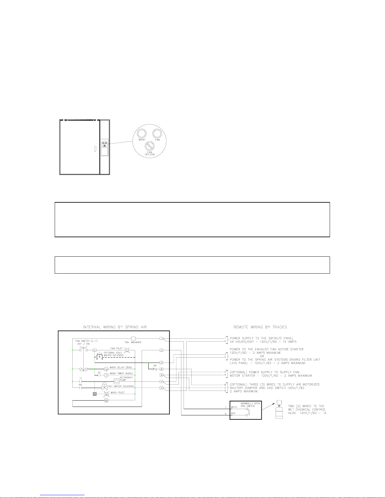
MP10C & MP10H Wash Panel
Figure 2
Cold Water Spray P anel s (SB10C/MPx0C/APx0C)
When the fan selector switch is rotated to the “ON” position the cold water spray solenoi d val ve i s energized. The cold-
water spray operates while the exhaust fan is operating. The cold-water spray can be observed by looking int o t he i n l et
slot of the grease extractor. All nozzles should be spraying to f orm a uniformed water pattern along the length of the
ventilator.
To stop the exhaust and supply fan rotate t he selector switch to the “OFF” position. The green fan “ON” pilot and the
exhaust fan will turn off.
Cold Water Spray P anel s (SB10C/MPx0C/APx0C).
In addition the cold-water spray solenoid valve will close.
: To start the exhaust fan rotate t he fan s elec tor s witch t o the “ON” pos iti on. The green “FAN ON” pilot and
Supply fan
damper through term inals 4, 8, & 9. The dam per mot or is energized
through terminals 4, & 8. Once an end switch closes 120V/1/60
power is supplied back to the control panel through terminal 9. The
supply fan motor starter is then energized through terminal s 4 & 9.
When a motorized damper with end switch is not used in the
installation the field electrician must jumper terminals 8 & 9 in the
water wash panel to provide 120V/1/60 power to the supply fan motor
starter.
: Power is provided for a fresh air motorized shut off
SINGLE SEQUENCE WASH
MODEL: SB10C, SB10H
CAPACITY:
One ¾” (19 mm) to 1.25” (32 m m) hot water inlet and one ¾” (19 mm) to 1.25” (32 mm ) hot water outlet connections for
washing p to 46 ft. (14 m) of vent i l at or.
Model SB10C and SB10H control panel i nternal wiring
Figure 3
_____________________________________________________________________________________________
Spring Air Systems Water Wash Ventilator Mai ntenance Manual 11/01
3
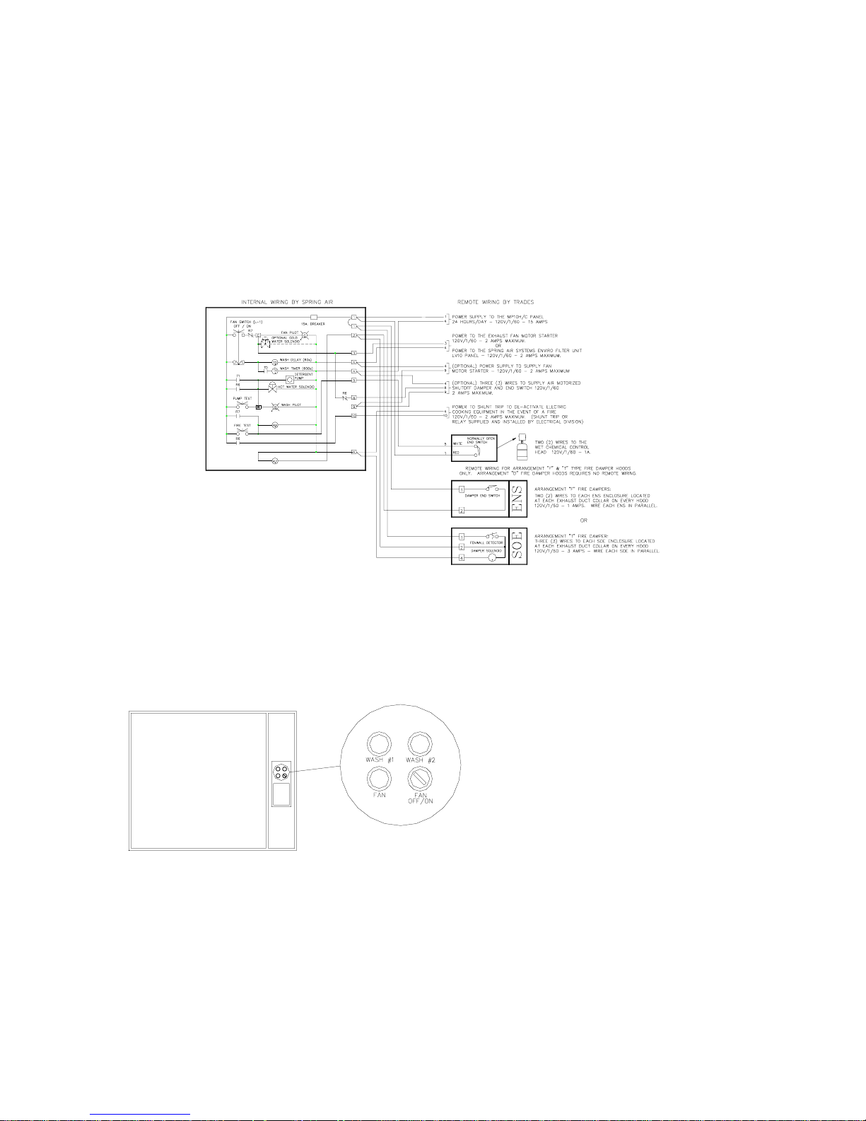
MODELS: MP10C, MP10H
CAPACITY:
One ¾” (19 mm) to 1.5” (38 m m) hot water inlet and one ¾” (19 mm ) to 1.5” (38 mm) hot water outlet connections for
washing up to 50 ft. (15 m) of vent i l at or.
When the selec t or switch has been rotated to the “OFF” posit i on, after a 60 second time delay, the blue “WASH” pil ot the
detergent pump and hot water solenoid valve are energized. The hot water and detergent mixture flow to the ventilator
and enter the grease extractor through an inlet pipe c onnected to the spray manifold. The detergent water mixture is
sprayed from nozzles spaced uniform ly along the length of the wash manif old washing the grease dirt and lint f rom the
grease extractor baffle and into the drain.
The wash continues f or the period of t ime set on the wash timer adjustable f rom 0 to 600 seconds. At the end of the
wash cycle the blue “WASH” pilot, the det ergent pump and the hot water sol enoid valve shut off. The sys tem remains
idle until the next time the fan selector switch is t urned to the “ON” position.
Single Sequence Wash MP 10C & M P10H Electrical Wiri ng
TWO SEQUENCE WASH
MODELS: MP20C, MP20H
CAPACITY
connections for washing up to 100 ft. (30 m) of ventilator.
MP20C & MP20H water wash panel
Figure 5
: One ¾” (19 mm to 1.5” (38 mm) hot water inl et and two ¾” (19 mm) to 1.5” (38 mm) hot water outlet
Figure 4
When the fan selector switch has been rotated to
the “OFF” position, after a 60 second delay, the
blue “WASH #1” pilot , the detergent pump, and t he
hot water solenoid #1 are energized.
The detergent and water mixture washes the first
group of ventilators (up to 50-ft . (15 m)). The wash
cycle remains on for t he length of time set on wash
timer #1 (T1) adj ustable f rom 0 to 600 s econds. A t
the end of wash cycle #1 the “W ASH #1” pilot and
the hot water solenoid #1 shut off and the blue
“WASH #2”
_____________________________________________________________________________________________
Spring Air Systems Water Wash Ventilator Mai ntenance Manual 11/01
4
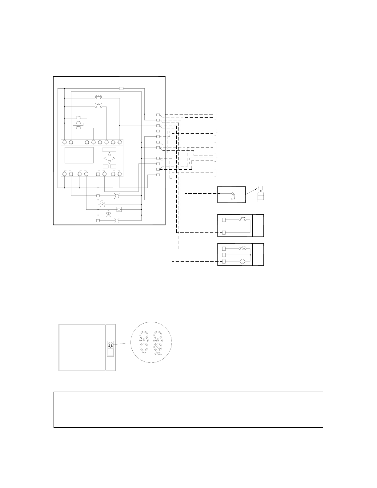
pilot and hot water solenoid valve #2 is energized. The detergent and water mixture washes the second group of
ventilators (up to 50 ft. (15 m )). The wash cycle cont inues for the length of t ime set on wash ti mer #2 (T2) adjustable
from 0 to 600 seconds. At the end of wash cycle #2 t he “WAS H #2” pilot detergent pum p and hot water solenoid valve
#2 shut off. The system remains idle until t he next ti me the fan selector switch is turned to the “ON” position.
INTERNAL WIRING BY SPRIN G AIR
CURCUIT BREAKER
FIRE TEST
PUMP TEST
FAN SWITCH
OFF/AUTO/ON
o
x
o
o
x
x
x
o
x
L
NI1
I: 1 2 3 4 5 6
Mo 09:00
Q: 1 2 3 4 RUN
SMART RELAY
Q1 Q2
C
H
REMOTE WIRING BY TRADES
1
POWER SUPPLY TO THE AP10H/C PANEL
4
24 HOURS/DAY - 120V/1/60 - 15 AMPS
POWER TO THE EXHAUST FAN MOTOR STARTER
120V/1/60 - 2 AMPS MAXIMUM.
3
4
POWER TO THE SP R ING AIR SYSTEMS E NV IRO FILTER U NIT
LV10 PANEL - 120V/1/60 - 2 AMPS MAXIMUM.
4
(OPTION A L ) POWER SUPPLY TO SUPPLY FAN
9
MOTOR STARTER - 120V/1/60 - 2 AMPS MAXIMU M
(OPTIONAL) THREE (3) WIRES TO SUPPLY AIR MOTORIZED
4
8
SHUTOFF DAMPER AND END SWITCH 120V /1/ 60
9
2 AMPS MAXIMUM.
POWER TO SHUNT TRIP TO DE-AC TIV AT E ELECTRIC
4
COOKING EQUIPMENT IN THE EVENT OF A FIRE
10
120V/1/60 - 2 AMPS MAXIMUM. (SHUNT TRIP OR
RELAY SUPPLIED AND INSTALLED BY ELECTRICAL DIVISION)
NORMALLY OPEN
END SWITCH
WHITE
5
RED
1
REMOTE WIRING FOR ARRANGEMENT "F" & "T" TYPE FIRE DAMPER HOODS
ONLY. ARRANGEMENT "D" FIRE DAMPER HOODS RE QU I RES NO REMOTE WIRING.
1
DAMPER END SWIT C H
2
1
FENWALL DETECTOR
2
DAMPER SOLENOID
4
I5I2 I3 I4 I6
OKQ3ESC
FAN PILOT
OPTIONAL COLD
WATER SOLENOID
HOT WATER SOLENOID
Q4
G
B
DETERGENT
PUMP
WASH PILOT
1
1
2
5
3
4
4
4
8
9
10
Two Sequence Wash Panel Model A P10C & AP10H Electrical Wiring
Figure 6
OR
TWO (2) WIRES TO THE
WET CHEMI CAL CONTROL
HEAD 120V/1/60 - 1A.
ARRANGEMENT "F" FIRE DAMPERS:
TWO (2) WIRES TO EACH ENS ENCLOSURE LOCATED
AT EACH EXHAUST DUCT COLLAR ON EVERY HOOD
120V/1/60 - 1 AMPS. WIRE EACH ENS IN PARALLEL.
ENS
OR
ARRANGEMENT "T" FIRE DAMPER:
THREE (3) WIRES TO EACH SOE ENCLOSURE LOCATED
AT EACH EXHAUST DUCT COLLAR ON EVERY HOOD
120V/1/60 - 3 AMPS - WIRE EACH SOE IN PARALLEL.
SOE
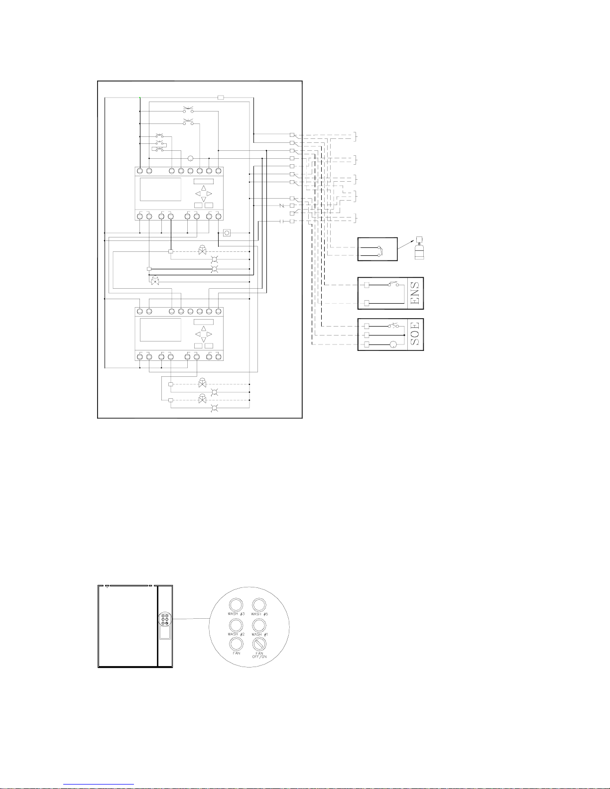
THREE SEQUENCE WASH
MODELS: MP30C, MP30H
CAPACITY
One ¾” (19 mm ) to 1.5” (38 mm) hot water inlet and one ¾” (19
mm) to 1.5” (38 m m) hot water outlet connect ion piped to three
¾” (19 mm)to 1.5” (38 mm) hot water connections to three
groups of hoods for washing up to 150 ft. (45 m) of ventilators.
When the fan selector switch has been rotated to the “OFF”
position, after a 60 s econd t im e del ay, t he blue “WASH #1” pilot, the
detergent pump, and the hot water solenoi d #1 are energi zed.
MP10C & MP10H Water Wash Panel
Figure 7
Three sequence control panels have remote hot water solenoid valves. A 120/1/ 60 signal is supplied to each hot water
solenoid valve through terminals H1, H2, H3, and 4 in the control panel.
Terminals Component
H1 & 4 Hot water solenoid valve #1
H2 & 4 Hot water solenoid valve #2
H3 & 4 Hot water solenoid valve #3
_____________________________________________________________________________________________
Spring Air Systems Water Wash Ventilator Mai ntenance Manual 11/01
5
INTERNAL WIRING BY SPRING AIR
Set clock
and length
of first
wash here.
B01=WASH1
B04=CLOCK
Set length
of second
and third
wash here.
B02=WASH2
B03=WASH3
L
N
I: 1 2 3 4 5 6
Mo 09:00
Q: 1 2 3 4 RUN
SMART RELAY
Q1 Q2
C
LN
I: 1 2 3 4 5 6
Q: 1 2 3 4 RUN
SMART RELAY
Q1 Q2
FAN SWITCH
OFF/AUTO/ON
ox
o
ox
x
xxo
CURCUIT BREAKER
FIRE TEST
PUMP TEST
1
1
2
R5
ESC OK
Q3
FAN PILOT
OPTIONAL COLD
WATER SOLENOI D
I3I2 I6I4 I5
ESC OK
Q3 Q4
I6I4I3I2 I5
Q4
DETERGENT
PUMP
HOT WATER SOLENOID #1
WASH PILOT #1
B
G
I1
H1
I1
5
3
4
4
4
R5
8
9
R5
10
REMOTE WIRING BY TRADES
ALL HOT WATER SOLENOID VALVES
ARE LOCATED REMOTE FROM PANEL
1
POWER SUPPLY TO THE AP20H/C PANEL
4
24 HOURS/DAY - 120V/1/60 - 15 AMPS
POWER TO THE EXHAUST FAN MOTOR STARTER
120V/1/60 - 2 AMPS MAXIMUM.
3
4
POWER TO THE SPRING AIR SYSTEMS ENVIRO FILTER UNIT
LV10 PANEL - 120V/1/60 - 2 AMPS MAXIMUM.
4
(OPTIONAL) POWER SUPP LY TO SUPPLY FAN
9
MOTOR STARTER - 120V/1/60 - 2 AMPS MAXIMUM
(OPTIONAL ) THREE (3) WIRES TO SUPPLY AIR MOT ORIZED
4
8
SHUTOFF DAMPER AND END SWITCH 120V/1/60
9
2 AMPS MAXIMUM.
POWER TO SHUNT TRIP T O DE-ACTIV ATE ELECTRIC
4
COOKING EQUIPMENT IN THE EVENT OF A FIRE
10
120V/1/60 - 2 AMPS MAXIMUM. (SHUNT TRIP OR
RELAY SUPPLIED AND IN STALLED BY ELECTRICAL DIVISION)
WHITE
5
RED
1
1
2
1
2
4
OR
NORMALLY OPEN
END SWITCH
REMOTE WIRING FOR ARRANGEMENT "F" & "T" TYPE FIRE DAMPER HOODS
ONLY. ARRANGEMENT "D" FIRE DAMPER HOODS REQUIRES NO REMOTE WIRING.
DAMPER END SWITCH
FENWALL DETECTOR
DAMPER SOLENOID
TWO (2) WIRES TO THE
WET CHEMICAL CONTROL
HEAD 120V/1/60 - 1A.
ARRANGEMENT "F" FIRE DAMPERS:
TWO (2) WIRES TO EACH ENS ENCLOSURE LOCATED
AT EACH EXHAUST DUCT COLLAR ON EVERY HOOD
120V/1/60 - 1 AMPS. WIRE EACH ENS IN PARALLEL.
ARRANGEMENT "T" FIRE DAMPER:
THREE (3) WIRES TO EACH SOE ENCLOSURE LOCATED
AT EACH EXHAUST DUCT COLLAR ON EVERY HOOD
120V/1/60 - 3 AMPS - WIRE EACH SOE IN PARALLEL.
OR
H2
H3
HOT WATER SOLENOID #2
WASH PILOT #2
B
HOT WATER SOLENOID #3
WASH PILOT #3
B
Three Sequence Wash Panel Models A P30C and AP30H Electrical
Figure 8
The detergent water mixture washes the firs t group of ventilators (up to 50-ft. (15m)). The wash cycle continues for the
length of tim e set on wash tim er #1 (T1), adj ust able from 0 t o 600 sec onds. At the end of wash cycl e #1 the blue WASH
#1” pilot and the hot water solenoid valve #1 shut off and the blue “W ASH #2” pilot and hot water solenoid valve #2
energize. The detergent and water m i xture washes the s econd group of ventil ators (up to 50 f t. (15m )). The wash cyc le
continues for t he length of ti m e set on wash tim er #2, adjus table f rom 0 to 600 s econds . A t t he end of wash cyc le #2 t he
blue “WASH #2” pilot and the hot water solenoid valve #2 shut off and the blue “WASH #3” pilot and the hot water
solenoid valve #3 energize. The detergent water m ixture washes t he third group of venti lators (als o up to 50 f t. (15 m )).
At the end of wash cycle #3 the blue “W ASH #3” pil ot the hot water solenoid valve #3 and the det ergent pump shut of f.
The system remains idle until the next time the f an selector switch is rotated to “ON” position.
FOUR AND FIVE SEQUENCE WASH SYSTEMS
Four and five sequence wash control panels operate sim ilarly
to the three-sequence wash. After the third wash cycle is
complete the system proceeds to the fourth and fifth wash
cycles.
Due to space limitat ions within the kitchen the four and five
sequence wash system also have remote solenoid valves.
The detergent pump and tank are still located in the wash
control panel. See wiring and piping diagram s in the back of
MP40C & MP40H Water Wash Panel
Figure 9
the manual for the four and five sequence wash systems.
_____________________________________________________________________________________________
Spring Air Systems Water Wash Ventilator Mai ntenance Manual 11/01
6
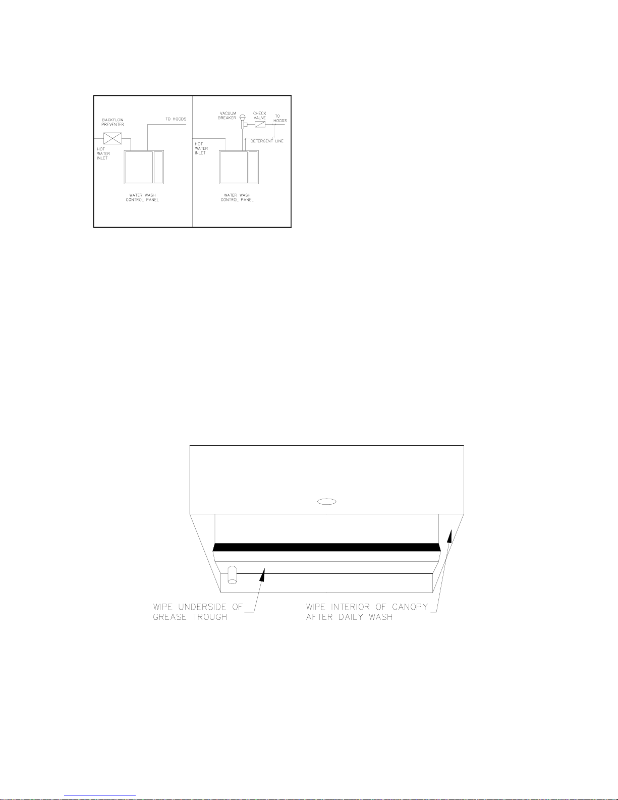
REMOTE PIPING
All remote piping m ust meet applicabl e local plumbing codes.
The panel must be install ed with adequate protection to stop
the flow of detergent back into t he potable water supply. This
may be accom plished, depending on the munici pality, with a
vacuum breaker and check valve assembly or a back flow
preventor. SPRING AIR SYSTEMS will always prepipe the
detergent line into the main hot water outlet pipe in the
plumbing cabinet unless advised to do otherwise prior to
shipment.
IT IS IMPORTANT TO CHECK WITH LOCAL PLUMBING
INSPECTORS TO DETERMINE WHAT IS ACCEPTABLE
PRACTICE IN YOUR JURISDICTION.
Backflow Preventor Vacuum Breaker
Figure 10
CLEANING THE EXTERIOR
Normal soil can be rem oved with a mild detergent water mixture applied to a c l oth.
To remove baked on grease, apply a cleanser to a dam p cloth or sponge and rub on the metal in t he direction of the
polishing lines. DO NOT RUB IN A CIRCULAR MOTION. Burnt deposi ts, which do not respond, can usuall y be removed
by rubbing the surface with SCOTCH-BRITE scouring pads or STAINLESS scouring pads. Do not use ordinary steel
wool. Heat tint can be removed by a vigorous scouring in the direction of the polish lines us ing SCOTCH-BRITE or
STAINLESS scouri ng pads in conjunction with powdered cleanser.
Once the wash cycle(s) are com plete wipe of t he int erior s urfac e of t he ventil ator c anopy and the unders ide of the grease
trough and skirt.
During the wash cycle(s) condensation may form on these surfaces. The condensation will assist in cleaning off any
grease, dirt or lint, which may have built up during the daily operation.
_____________________________________________________________________________________________
Spring Air Systems Water Wash Ventilator Mai ntenance Manual 11/01
Cleaning the Ventilator Ex terior
Figure 11
7

WASH TIMER SETTINGS
All SB10C, MP10C, MP20C, MP30C, MP40C, & MP50C wash control panel timers are factory set at two mi nut es.
All SB10H, MP10H, MP20H, MP30H, MP40H, & MP50H wash control panel timers are factory set at three minutes.
After the fi rst four days of operation open the front access door on the grease extractor. V isually chec k if the baf fle and
interior surfaces are cl ean. I f there are greas e depos its chec k that the hot water pres sure i s bet ween 40 psi (2.8 kg/cm2)
and 70 psi (4.2 kg/cm2) and t he hot water temperature is between 120 F (49 C) and 180 F (82 C). If there is adequate
temperature and pressure either use a higher detergent concentration or increase the wash time.
• The detergent concentrat ion can be adjusted by increasing the cam set ting on the side of the detergent pump.
Loosen the wing nut on the side of the detergent pump and rotate the cam to the next setting. The cam is
adjustable from 0 to 6, 6 bei ng the highest detergent concentrat ion. Only increase one setting at a time. Inspect
the interior each day and adjust unti l al l surfaces are clean.
• Only increase the wash time in 30-s econd intervals until all baff les and exposed interior grease extractor surfac es
are clean.
For type “C” water wash ventilators check t hat the cold water pressure is at least 10 psi 1.4 kg/cm2).
AUTOMATIC WASH SYSTEMS:
SBA10H, SBA10C, AP10H, AP10C, AP20H, AP20C, AP30H, AP30C, AP40H,
AP40C, AP50H, & AP50C
Automatic Wash Panel
Figure 12a
The automatic wash control panel s are equipped with a solid-state microprocessor. The f an
selector switch is replac ed with a three-posi tion “OFF/ AUTO/ON” s witch. In t he “OFF” and “ON”
positions the control panel operates identical to the standard SB, & MP manual wash panels.
When the fan switc h is rotated to the “AUTO” position the solid-state time cl ock controls the
OFF/ON operation of the exhaust fan, supply fan and wash cycle.
Setting the clock (T6) i s as simple as set ting a digital watch.
INTERNAL WIRING BY SPRING AIR
FAN SWITCH
OFF/AUTO/ON
ox
o
ox
x
xxo
LQ2NI1I2
CURCUIT BREAKER
I3 I4 I5 I6
I: 1 2 3 4 5 6
Mo 09:00
Q: 1 2 3 4 RUN
SMART RELAY
Q1
ESCQ3OK
FAN PILOT
C
H
Q4
G
OPTIONAL COLD
WATER SOLENOID
HOT WATER SOLENOID
B
DETERGENT
PUMP
WASH PILOT
1
5
3
8
9
4
4
ALL REMOTE ELECTRIAL WIRING
SHALL CONFORM TO ALL LOCAL
AND NATIONAL CODE REQUIREMENTS
REMOTE WIRING BY TRADES
1
POWER SUPPLY TO THE SB10H/C PANEL
4
24 HOURS/DAY - 120V/1/60 - 15 AMPS
POWER TO THE EXHAUST FAN MOTOR STARTER
120V/1/60 - 2 AMPS MAXIMUM.
3
4
POWER TO THE SPRING AIR SYSTEMS ENVIRO FILTER UNIT
LV10 PANEL - 120V/1/60 - 2 AMPS MAXIMUM.
4
(OPTIONAL) POWER SUPPLY TO SUPPLY FAN
9
MOTOR STARTER - 120V/1/60 - 2 AMPS MAXIMUM
(OPTIONAL) THREE (3) WIRES TO SUPPLY AIR MOTORIZED
8
4
SHUTOFF DAMPER AND END SWITCH 120V/1/60
9
2 AMPS MAXIMUM.
WHITE
1
RED
5
NOTE 1:
NORMALLY OPEN
END SWITCH
OR
TWO (2) WIRES TO THE
WET CHEMICAL CONTROL
HEAD 120V/1/60 - 1A.
MOTOR STARTERS OVERLOADS
NOTE 2:
AND DISCONNECTS BY
ELECTRICAL DIVISION
SBA10C and SBA10H Automatic Wash Panel Wiring Sc hemat i c
Figure 12b
_____________________________________________________________________________________________
Spring Air Systems Water Wash Ventilator Mai ntenance Manual 11/01
8

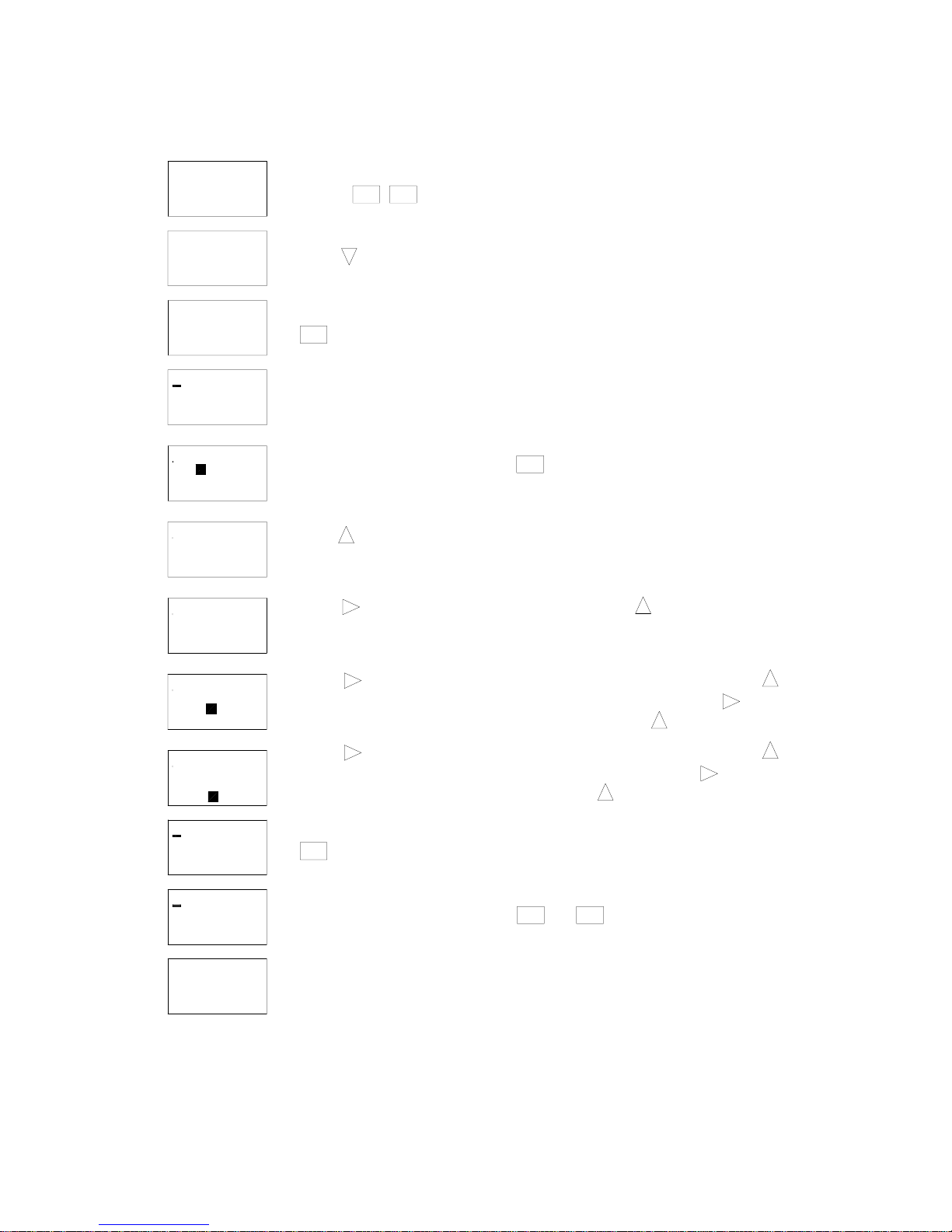
Programming the SMARTRELAY Time Clock
r
Setting the Clock Time and Day
I: 1 2 3 4 5 6
Mo 09:00
Q: 1 2 3 4
>Set Clock
Set Param
Set Clock
Mo 09:00
MM. DD. YY
11. 13. 01
LN
I3
I2I1
I: 1 2 3 4 5 6
Mo 09:00
Q: 1 2 3 4
SMART RELAY
Q1
1. Press these two buttons together
ESC
2. Press
OK
3. To change the day of week press
Q2
OK
I5I4 I6
OKESC
Q3 Q4
or until the correct day appears.
Set Clock
Su 09:00
MM. DD. YY
11. 13. 01
Set Clock
Su 11:25
MM. DD. YY
11. 13. 01
Set Clock
Su 11:25
MM. DD. YY
4. To change the time press once. The hour will be highlighted. Press
or
Adjust the minutes by pressing
5. To change the date press again. The month will be highlighted. Press
Adjust the day by pressing
move to year. Adjust the year by pressing
6. You have finished setting the clock.
until the correct hour appears.
or
until the correct month appears.
or
Press to move to minutes.
or
until correct minutes appears.
Press to move to day.
until correct day appea r . Pre ss to
or
until correct year appea
11. 11. 01
I: 1 2 3 4 5 6
Su 11: 25
7. Press
ESC
and
ESC
to return to the operating screen.
Q: 1 2 3 4
_____________________________________________________________________________________________
Spring Air Systems Water Wash Ventilator Mai ntenance Manual 11/01
9
I: 1 2 3 4 5 6
Mo 09:00
Q: 1 2 3 4
Setting the Weekly Fan “ON” and “OFF” Times
1. Press these two buttons together
ESC OK
>Set Clock
Set Param
Set Clock
>Set Param
B04: No1
D = MTWTFSS
On = 06: 00
Off = 23: 00
B04: No1
D = MTWTFSS
On = 06: 00
Off = 23: 00
B04: No1
D = MTWTF-S
On = 06: 00
Off = 23: 00
B04: No1
D = - TWTF- -
On = 06: 00
Off = 23: 00
B04: No1
D = - TWTF- -
On = 0 6: 00
Off = 23: 00
2. Press
3. Press
OK
4. The clock has been factory set to turn the fan on at 6:00 a.m. and off
at 23:00 hours or 11:00 p.m. When the fan shuts off th e wash activates.
5. To change the above settings press
6. Press to remove Monday from the weekly schedule. The - dash indicates
the fan will not start automatically any given day.
7. Press to move to the next day of the week. Press each time the fan is
not required to operate on that given day. The screen on the left indicates the
fan will not automatically operate on Satur day or Sunday.
8. Press to move to the hour that the fan will start in the morning. Press
to change the hour you want the fan to start in each morning. Press to move
to the minute the the fan will start in the morning. Press to change the minutes.
OK
The cursor will move to M = Monday.
B04: No1
D = - TWTF- -
On = 06: 30
Off = 2 3: 00
B04: No1
D = MTWTF- -
On = 06: 30
Off = 22: 30
9. Press to move to the hour that the fan will stop in the evening. Press
to change the hour you want the fan to stop each evening. Press to move
to the minute the fan stop in the evening. Press to change the minutes.
10.Press
OK
B04: No1
D = MTWTF- -
On = 06: 30
Off = 22: 30
I: 1 2 3 4 5 6
Mo 09:14
Q: 1 2 3 4
11. If your selection is complete press and to return the the operating screen.
12. You have completed programming one weekly fan "On" and "Off" cycling. If you wish
to program a second (Weekend Operation) or third weekly setting go the the section
"Setting Weekend Operation"
ESC ESC
_____________________________________________________________________________________________
Spring Air Systems Water Wash Ventilator Mai ntenance Manual 11/01
10
 Loading...