


KES Enviro
Maintenance Manual
___________________________
Spring Air Systems Inc., Oakville, Ontario
Phone (905) 338-2999, Fax (905) 338-0179, info@springairsystems.com


KES Enviro Maintenance Manual
Table of Contents
Introduction....................................................................................... 1
The System...................................................................................... 1
Control System: Water Wash Ventilator SB, SBA Panels............... 2
Control System: Water Wash Ventilator AP, MP Panels.................. 4
Filter Hood or Dry Grease Extractor................................................. 5
Control Circuit.................................................................................. 7
Setting the Day and Time................................................................ 13
Setting the Weekday Fan “ON” and “OFF” Times............................ 14
Setting Weekend Operation............................................................. 15
Odor Spray Systems........................................................................ 15
Where to Purchase Filters................................................................ 19
Replacement Filter Equivalents........................................................ 19
Trouble Shooting.............................................................................. 20
KES Maintenance Sch edule............................................................ 22
KES Enviro Start-Up Report............................................................. 24
Filter Frequency Chart...................................................................... 26

KES OPERATIONS AND MAINTENANCE MANUAL
INTRODUCTION
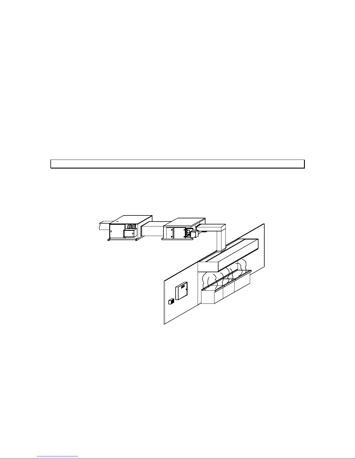
The SPRING AIR SYSTEMS INC. kitchen Enviro system (KES), Exhaust Cleaning Assembly for Kitchen
Exhaust Duct, “Enviro Unit” is ULC and UL listed for use in a commercial kitchen exhaust system. KES
units are available in sizes ranging from 1,000 CFM to 40,000 CFM for indoor or outdoor applications.
The primary function of a KES Enviro unit is to filter the grease, lint and dust particles and remove the odor
from the exhaust air.
The Underwriters’ Laborato ries of Canada Limited (ULC) listing allows the use of non-NFPA-96 exhaust
ductwork after the exhaust air is discharged from the KES unit. In other words the discharge ductwork can
be treated similar to standard HVAC ducting. Also after the kitchen exhaust air has been treated with the
KES unit the exhaust can be discharged outdoors at low levels.
The Underwriters Laboratories Inc. (UL) listing allows the kitchen exhaust air to be discharge to atmosphere
at low levels.
Prior to any installation the installer must seek approval from the authorities having jurisdiction.
THE SYSTEM
The grease -laden air rises from the cooking equipment into a UL or ULC exhaust hood. The exhaust hood
removes some of the airborne grease particulate. Typically most micron and submicron particles escape
Exhaust to
atmophere at
low level
Discharge Ductwork
KESF Fan Box
Interconnecting Ductwork
KES-ISH Filter Box
Water Wash
Panel
Remote
RPW(D) Panel
NFPA-96 Ductwork
Listed Exhaust Hood
Appliance Line-up
into the exhaust ductwork. The exhaust ducting is connected from the hood to the inlet of the KES Enviro
unit. This exhaust ductwork must be supplied and installed in accordance with the NFPA -96 code.
KES System Schematic
Figure 1
Within the KES unit the exhaust air travels through three stages of particulate filters:
1Two (2) inches pleated - 30 percent ASHRAE 52-76 prefilters.
2Twenty-one (21) to twenty -two (22) inch bag - 90 percent ASHRAE 52-76 filters.
3Twelve (12) inches box - 95 percent DOP filters.
Enviro Maintenance Manual 2004
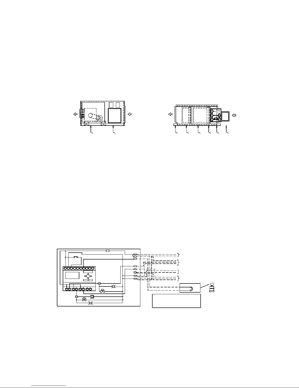
KES-ISH
KESF
Once through the particulate filter sections the exhaust air enters the optional odor removal section. The
odor section is only required when discharging cooking smells may be offensive. This section consists of
two optional odor removal systems.
1.Odor Cells filled with activated alumina impregnated with potassium permanganate. The odor is controlled
through a combination of sorption and the chemical modification of the gaseous contaminates. The
odor media is non-toxic and non-flammable.
1.Odor spray solution. The odor is control by spraying an odor reducer into the exhaust air stream
intermittently during the operation of the cooking systems.
EXHAUST OUTLET
TO THE OUTDOORS
Exhaust Fan
Odour Removal Section
EXHAUST OUTLET
TO THE KESF FAN
Fire Damper
Box Filter
Bag Filter
2 inch prefilter
Pressure switches
LV-10 Panel
2.
KES-ISH and KESF Enviro components
Figure 2
The exhaust air is discharged from the KES unit through a single width, single inlet (SWSI) or double width,
double inlet (DWDI) exhaust fan. The discharge ductwork transfers the exhaust air outdoors.
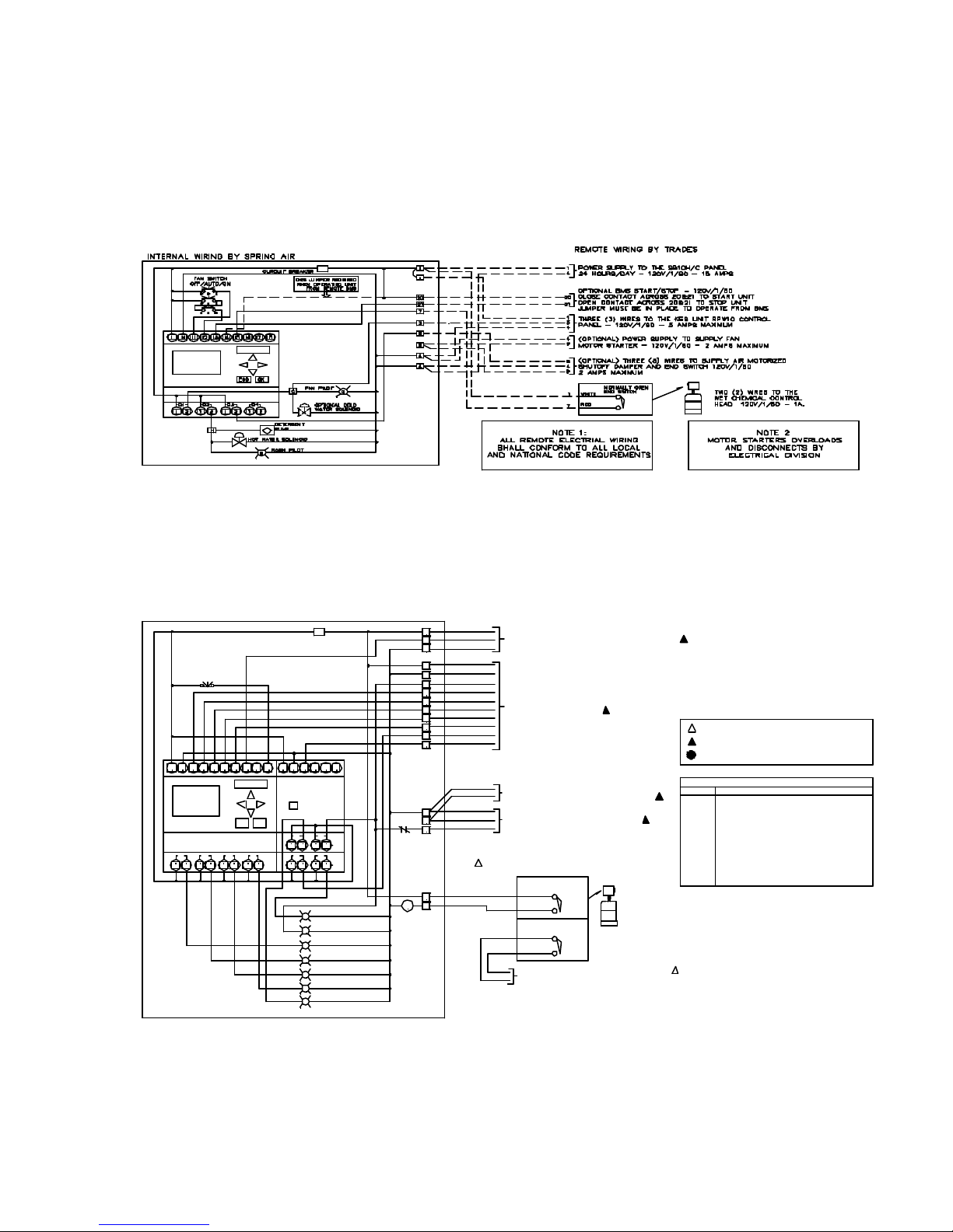
CONTROL SYSTEM
Water Wash Ventilator System: SB, SBA Panels
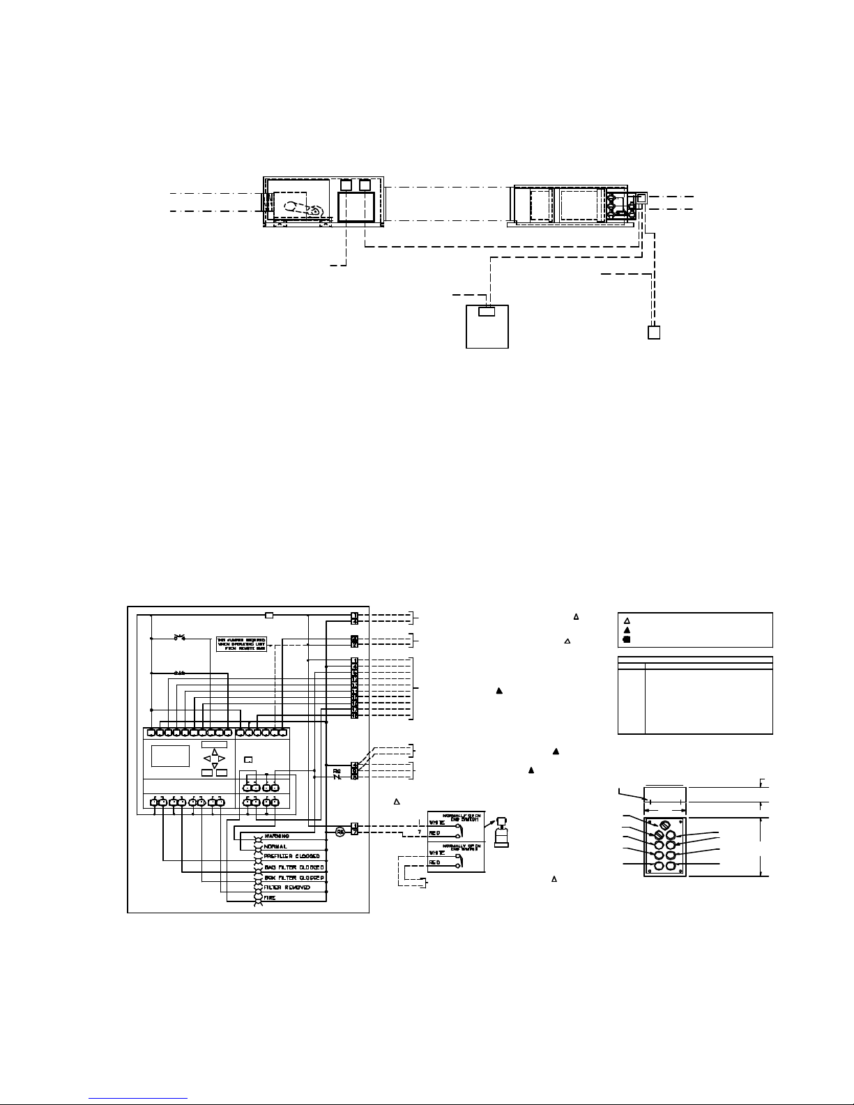
The KES unit off/on operation is controlled from the SB, or SBA water wash ventilator control panel. Power
is fed to the RPW10 panel through terminals 1 & 4. When the fan selector switch on the water wash control
panel closes a signal is sent through terminal 3 to the RPW10 panel to activate the KES unit.
INTERNAL WIRING BY SPRING AIR
FAN SWITCH
OFF/ON
L N
Mo 09:00
01. 20. 03
LOGO!
Q1
Q2
1 2
1 2 1 2Q31 2
H
I4I1 I2 I3 I5 I6 I7
ESC OK
HOT WATER SOLENOID
CURCUIT BREAKER
I8
Q4
B
DETERGENT
PUMP
WASH PILOT
C
FAN PILOT
OPTIONAL COLD
WATER SOLENOID
1
1
7
3
8
9
4
4
G
ALL REMOTE ELECTRIAL WIRING
SHALL CONFORM TO ALL LOCAL
AND NATIONAL CODE REQUIREMENTS
REMOTE WIRING BY TRADES
1
POWER SUPPLY TO THE SB10H/C PANEL
4
24 HOURS/DAY - 120V/1/60 - 15 AMPS
1
THREE (3) WIRES TO THE KES UNIT RPW10 CONTROL
3
PANEL - 120V/1/60 - 5 AMPS MAXIMUM.
4
4
(OPTIONAL) POWER SUPPLY TO SUPPLY FAN
9
MOTOR STARTER - 120V/1/60 - 2 AMPS MAXIMUM
8
(OPTIONAL) THREE (3) WIRES TO SUPPLY AIR MOTORIZED
4
SHUTOFF DAMPER AND END SWITCH 120V/1/60
9
2 AMPS MAXIMUM.
NORMALLY OPEN
END SWITCH
1
WHITE
RED
7
NOTE 1:
TWO (2) WIRES TO THE
WET CHEMICAL CONTROL
HEAD 120V/1/60 - 1A.
EXHAUST INLET
FROM THE HOOD
Typical KES wiring to SB10C water wash panel
Figure 3
Enviro Maintenance Manual 2004
The “NORMAL” operation pilot energizes on the RPW10 remote kitchen annunciation panel. After 30
seconds the RPW10 control circuit is activated. The RPW10 is a stainless steel panel located remote from
the SB or SBA panel. See Figure 5 for RPW10 wiring and dimensions. The KES exhaust fan motor is
energized through the terminals 5 & 4 to the LV10 J-Box located on the KESF fan section. See figure 11 for
internal wiring of the LV10 J-box. See figure 3 or 5 for a SB water wash panel.
Mo 09:00
01. 20. 03
LOGO!
Typical KES wiring to SBA10C water wash panel
Figure 4
RPW10 ELECTRICAL DATA
OVERIDE SWITCH
I3I2NL I1
I4
Mo 09:00
01. 20. 03
LOGO!
1 2Q121 1
15 AMP CURCUIT BREAKER
I7 I8I6I5
L
AUX!
OKESC
Q3
Q4Q2
2Q312
I4I3I1N I2
RUN/STOP
Q2Q1
21
21
Q4
21
21
WARNING
NORMAL
PREFILTER CLOGGED
BAG FILTER CLOGGED
BOX FILTER CLOGGED
FILTER REMOVED
FIRE
1
3
4
1
4
5
12
13
14
15
16
17
18
4
9
R6
8
1
7R6
THREE (WIRES) TO THE WATER WASH CONTROL
PANEL - 120V/1/60 - 10 AMPS
TO KES UNIT LV10 PANEL ON FILTER
BOX - TEN (10) WIRES
120V/1/60 - 10 AMPS.
(OPTIONAL) POWER SUPPLY TO SUPPLY FAN
MOTOR STARTER, 120V/1/60 - 2 AMPS
(OPTIONAL) THREE (3) WIRES TO
MOTORIZED INLET DAMPER AND END
SWITCH, 120V/1/60 - 1 AMP
TWO (2) WIRES TO THE WET CHEMICAL
CONTROL HEAD, 120V/1/60 - 1AMP
NORMALLY OPEN
END SWITCH
1
WHITE
7
RED
NORMALLY OPEN
END SWITCH
WHITE
RED
DRY CONTACT FOR BUILDING FIRE ALARM
FIRE ANUNCIATION, 5 AMPS MAXIMUM, N/O
RPW10 Wiring Schematic
Figure 5
POWER WIRING BY GENERAL CONTRACTOR
CONTROL WIRING BY MECHANICAL CONTACTOR
FACTORY WIRING BY SPRING AIR SYSTEMS
TERMINAL DESCRIPTION
1&4
5
12
13
14
15
16
17
18
20&21
LEGEND
POWER SUPPLY FROM BREAKER PANEL
KES FAN/NORMAL OPERATION
PREFILTER CLOGGED
BAG FILTER CLOGGED
BOX FILTER CLOGGED
FILTER OUT/LOW AIR
FIRESTAT - HIGH LIMIT
0DOR SPRAY UNIT
LV10 RESET
BMS START/STOP
Enviro Maintenance Manual 2004
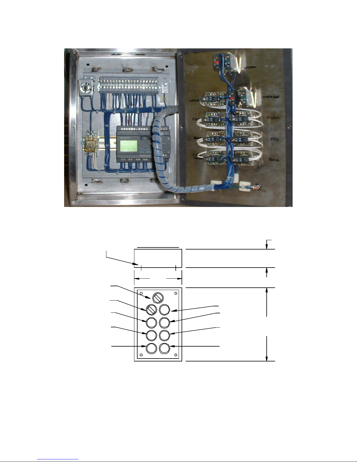
PANEL MOUNTING
HOLES LOCATED
IN PANEL BACK.
8.0"
5.0"
FILTER
OVERIDE
NORMAL
PREFILTER
CLOGGED
BAG FILTER
CLOGGED
WARNING
FIRE
BOX FILTER
CLOGGED
FILTER
REMOVED
14.0"
Remote RPW10 Panel Dimensions
Figure 6
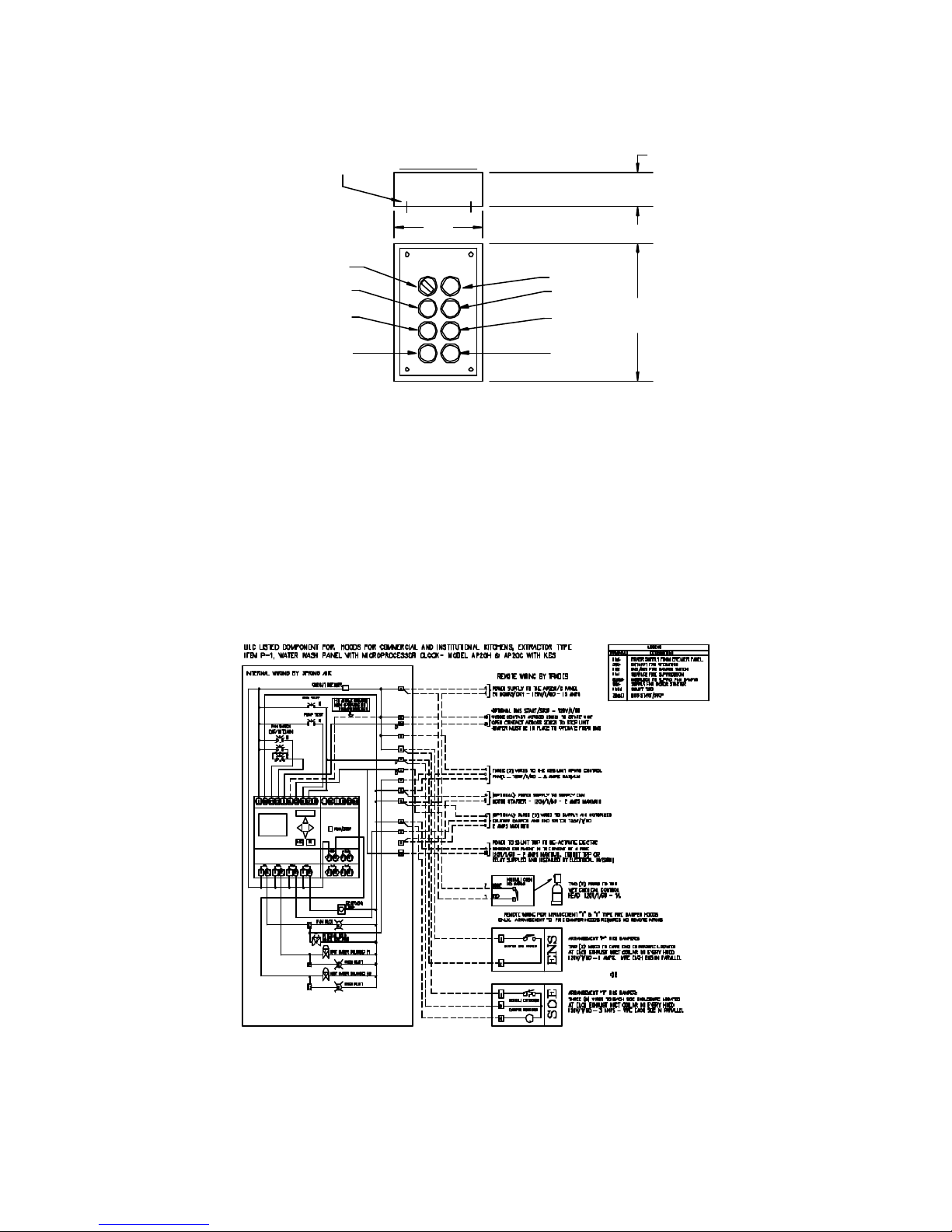
Water Wash Ventilator System: AP, MP Panels
The KES unit off/on operation is controlled from the MP or AP water wash ventilator control panel. The fan
selector switch on the water wash control panel closes and sends power through terminals 3 & 4 to the
RPW10 remote panel to energize the exhaust fan through terminals 5 & 4 in the LV -10 J-Box. (The LV10 JBox is mounted on the KES-ISH filter section).
The “NORMAL” operation pilot energizes on the RPW10. After 30 seconds the KES control circuit within the
RPW10 remote panel is activated. See Figure 5 for RPW10 internal wiring. The exhaust fan motor is
energized through the terminals 9 & 4 to the motor starter located on the KESF fan section. See figure 11
for internal wiring of LV10 J-Box with RPW10 remote panel.
Mo 09:00
01. 20. 03
LOGO!
Typical KES wiring to AP20C water wash panel
AUX!
Figure 7
Enviro Maintenance Manual 2004
KESF
EXHAUST DISCHARGE
DUCTWORK DUCTWORK AS REQUIRED
POWER SUPPLY
TO KESF FAN UNIT
FIELD INTERCONNECTING
INTERLOCK BETWEEN KES-ISH LV10 AND KESF MOTOR STARTER
THREE (3) WIRES TO
RPW10 PANEL FROM
WATER WASH PANEL
POWER SUPPLY
TO SB10 WASH PANEL
120V/1/60
KES-ISH
POWER SUPPLY
TO RPD10 REMOTE
WATER WASH
PANEL MODEL
SB10C OR SB10H
TEN (10) WIRES FROM
THE RPW10 CONTROLLER
FROM THE KES-ISH LV10
J-BOX - 120V/1/60
CONTROLLER
EXHAUST INLET
RPW10
DUCTWORK
Remote wiring of KES Enviro units with Water Wash Hood and Panel
Figure 8
Filter Hood or Dry Grease Extractor: RPD10 Remote Panel
The KES unit off/on operation is controlled from RPD10 remote annunciation panel. The fan selector switch
on the RPD10 remote panel closes and sends power through terminals 5 & 4 to the LV10 J-Box to energize
the exhaust fan circuit. (The LV10 J-Box is mounted on the KES-ISH filter section). The “NORMAL”
operation pilot on the RPD10 remote kitchen annunciation panel energizes and after 30 seconds the KES
control circuit within the RPD10 remote panel is activated. The exhaust fan motor is energized through the
terminals 5 & 4 to the motor starter. See fi gure 8 for the RPD10 remote panel wiring and figure 9 for
dimensions.
RPD10A ELECTRICAL DATA
FAN SWITCH
OFF/ON
OVERIDE SWITCH
I4I2L N I1 I3
I5 I6 I7 I8 L N
Mo 09:00
01. 20. 03
LOGO!
Q3Q1
1 2Q21 2 1 2Q41 2
15 AMP CURCUIT BREAKER
AUX!
ESC OK
I1 I2 I3 I4
RUN/STOP
Q1
2
1
Q3
2
1
POWER SUPPLY TO THE KES UNIT
RPD10 CONTROL PANEL - 120V/1/60 - 15 AMPS
OPTIONAL BMS START/STOP - 120V/1/60
CLOSE CONTACT ACROSS 20&21 TO START UNIT
OPEN CONTACT ACROSS 20&21 TO STOP UNIT
JUMPER MUST BE IN PLACE AS NOTED TO OPERATE FROM BMS
TO KES UNIT LV10 PANEL ON FILTER
BOX - TEN (10) WIRES
120V/1/60 - 10 AMPS.
(OPTIONAL) POWER SUPPLY TO SUPPLY FAN
MOTOR STARTER, 120V/1/60 - 2 AMPS
(OPTIONAL) THREE (3) WIRES TO
MOTORIZED INLET DAMPER AND END
Q2
1 2
Q4
1 2
SWITCH, 120V/1/60 - 1 AMP
TWO (2) WIRES TO THE WET CHEMICAL
CONTROL HEAD, 120V/1/60 - 1AMP
DRY CONTACT FOR BUILDING FIRE ALARM
FIRE ANUNCIATION, 5 AMPS MAXIMUM, N/O
OVERIDE
POWER WIRING BY GENERAL CONTRACTOR
CONTROL WIRING BY MECHANICAL CONTACTOR
FACTORY WIRING BY SPRING AIR SYSTEMS
TERMINAL
POWER SUPPLY FROM BREAKER PANEL
1&4
KES FAN/NORMAL OPERATION
5
PREFILTER CLOGGED
12
BAG FILTER CLOGGED
13
14 BOX FILTER CLOGGED
FILTER OUT/LOW AIR
15
FIRESTAT - HIGH LIMIT
16
0DOR SPRAY UNIT
17
18
LV10 RESET
BMS START/STOP
20&21
PANEL MOUNTING
HOLES LOCATED
IN PANEL BACK.
KES
OFF/ON
FILTER
NORMAL
PREFILTER
CLOGGED
BAG FILTER
CLOGGED
8.0"
RPD10 DIMENSIONAL DATA
LEGEND
DESCRIPTION
WARNING
FIRE
BOX FILTER
CLOGGED
FILTER
REMOVED
5"
14.0"
RPD10 Wiring Schematic
Figure 9
Enviro Maintenance Manual 2004
RPD10 Internal Wiring
Figure 10
PANEL MOUNTING
HOLES LOCATED
IN PANEL BACK.
5"
KES
OFF/ON
FILTER
OVERIDE
NORMAL
PREFILTER
CLOGGED
BAG FILTER
CLOGGED
8.0"
RPD10 Remote Panel Dimensions
Figure 11
Enviro Maintenance Manual 2004
WARNING
FIRE
BOX FILTER
CLOGGED
FILTER
REMOVED
14.0"

KESF
KES-ISH
EXHAUST DISCHARGE
DUCTWORK
POWER SUPPLY
TO KESF FAN UNIT
FIELD INTERCONNECTING
DUCTWORK AS REQUIRED
INTERLOCK BETWEEN KES-ISH LV10 AND KESF MOTOR STARTER
POWER SUPPLY
TO RPD10 REMOTE
EXHAUST INLET
TEN (10) WIRES FROM
THE RPD10 CONTROLLER
FROM THE KES-ISH LV10
J-BOX - 120V/1/60
RPD10
CONTROLLER
DUCTWORK
Remote wiring of KES Enviro units with Dry Hood
Figure 12
CONTROL CIRCUIT
Filter Clogged:
During normal operation of the KES unit three-filter stages collect grease, dust, and lint particulate. The type
of cooking equipment and the hours of operation determines the useful life of the individual filt ers.
P1 - PLEATED FILTER
CLOGGED SWITCH
(SET AT 1.0 in. W.C.)
P2 - BAG FILTER
CLOGGED SWITCH
(SET AT 1.0 in. W.C.)
P3 - BOX FILTER
CLOGGED SWITCH
(SET AT 1.2 in. W.C.)
PRESSURE SWITCHES LOCATED ON KES-ISH FILTER
SECTION TO RIGHT OF BOX FILTER ACCESS DOOR
P3 P2
P5
BOX
P4
BAG
FILTERFILTER
P1
PREFILTER
Pressure Switch Locations
Figure 13
P4 - BAG FILTER
REMOVED SWITCH
(SET AT 0.25 in. W.C.)
P5 - BOX FILTER
REMOVED SWITCH
(SET AT 0.25 in. W.C.)
COPPER TUBING
Enviro Maintenance Manual 2004

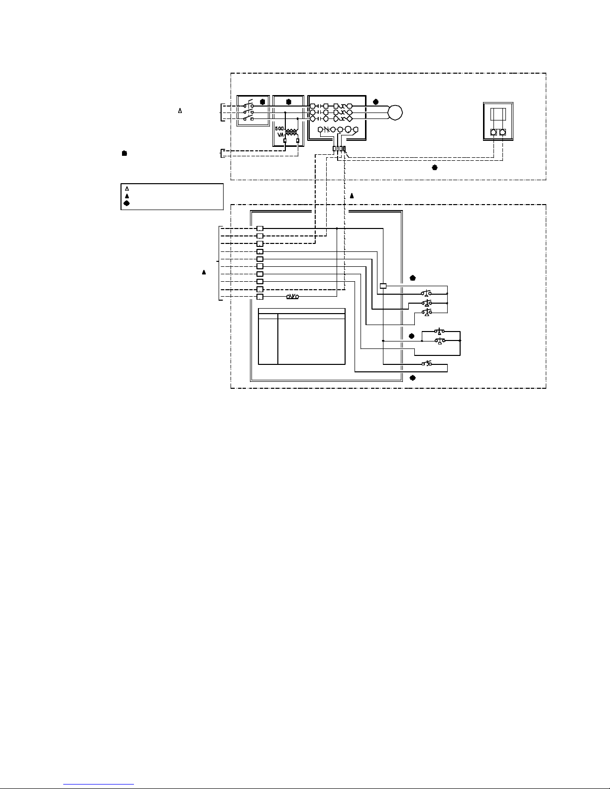
POWER SUPPLY
____V/3/60
____ FLA
POWER WIRING BY GENERAL CONTRACTOR
CONTROL WIRING BY MECHANICAL CONTACTOR
FACTORY WIRING BY SPRING AIR SYSTEMS
30 AMP DISCONNECT
IN EEMAC12 ENCLOSURE
MOUNTED ON FAN UNIT
KES TELE MOTOR STARTER
IN EEMAC12 ENCLOSURE
MOUNTED ON FAN UNIT
M1
O/L
T1L1
L1
T2T3L2
L2
L3
T2
L3T1T3
G1
95
96
M1
1
63 7
OPTIONAL ODOUR CONTROL PANEL
LOCATED ON KES FAN SECTION
EXHAUST FAN MOTOR
____ HP
A1A2
WIRING HARNESS IN
MOTOR STARTER
WIRING FROM EXHAUST FAN MOTOR STARTER
TO THE ODOUR CONTROL UNIT 120V/1/60
4.2 AMPS. MAXIMUM. WIRES BY SPRING AIR
THREE WIRES FROM LV10 PANEL TO EXHAUST FAN MOTOR STARTER BY
MECHANICAL WHEN KES FAN AND FILTER SECTIONS ARE SPLIT 120V/1/60, 5 AMPS
KES-ISH FILTER SECTION
KESF FAN SECTION
417
TEN (10) WIRES TO THE
TO REMOTE CONTROL STATION LOCATED IN
IN THE KITCHEN AREA MODEL RPD10 OR
RPW10 - 120V/1/60 - 10 AMPS.
1
4
5
12
13
14
15
16
17
18
TERMINAL
1&4 POWER FROM RPD10
KES FAN/NORMAL OPERATION
5
PREFILTER CLOGGED12
13
BAG FILTER CLOGGED
14
BOX FILTER CLOGGED
15
FILTER OUT/LOW AIR
16
FIRESTAT - HIGH LIMIT
17
0DOR SPRAY UNIT
18
LV10 RESET
RESET
LEGEND
DESCRIPTION
LV10 J-BOX
LOCATED ON
KES FILTER
UNIT
1
FILTER CLOGGED PRESSURE SWITCHES
P1
P1 - PREFILTER (SET AT 1.0" W.C.)
P2
P2 - BAG FILTER (SET AT 1.0" W.C.)
P3
P3 - BOX FILTER (SET AT 1.2" W.C.)
FILTER REMOVED SWITCHES
P4
P4 - BAG FILTERS (SET AT 0.25" W.C.)
P5
P5 - BOX FILTERS (SET AT 0.25" W.C.)
TH1
HI TEMP STAT LOCATED IN THE
EXHAUST INLET SET AT 225 °F
Typical indoor KES, motor starter, LV10 J-Box with odor spray wiring schematic
Figure 14
Pressure switches have been installed to determine when the filters are totally used and must be replaced.
As the filter reaches the grease loading capacity the static pressure across each filter increases. When the
maximum static pressure is reached the pressure switch is activated. The exhaust fan shuts off, the
“NORMAL” pilot energizes, and the kitchen remote panel annunciates a filter-clogged condition. (The
remote panel indicates which stage of filters has clogged; PREFILTER, BAG FILTER, or BOX FILTER.) In
addition the screen of the LOGO controller in the RPD10 or RPW10 has a text mes sage also indicating
which filter is clogged.
RPD10 or RPW10 LOGO controller indicating Box Filter clogged text messages
Change
Prefilter
LOGO!
AUX!
Change
Box Filter
LOGO!
LOGO!
Figure 15
Enviro Maintenance Manual 2004
Change
Bag Filter
AUX!
AUX!

The clogged filter must be replaced and the system reset to resume normal operation. If this condition
occurs during normally operating hours rotate the OVERRIDE selector switch and the fan will come back on.
The systems can run in the OVERRIDE position for about 4 hours. (See the section the OVERRIDE switch)
If the system runs longer than 4 hours the fan will shut down. The filters must be changed and the system
reset. It is recommended that the filters be changed prior to the filter clogged light energizing. A filter usage
chart is attached to record when the filters are being changed. Using this chart a regular maintenance
schedule can be set up to ensure constant uninterrupted operation of the commercial kitchen.
Filter Removed:
Should the bag or box filters be removed during normal operation the KES unit is automatically shut down.
A pressure switch across the bag filters and box filters monitors a minimum pressure drop of 0.25” W.C.
When the filter is removed the pressure differential falls and the pressure switch is activated. The exhaust
fan shuts off, the “FILTER REMOVED” pilot light on the RPD10 or RPW10 energizes and the screen of the
LOGO controller in the RPD10 or RPW10 has a text message indicating “FILTER REMOVED/LOW
EXHAUST. To resume normal operation the filter must be replaced and the system reset. (See the section
the OVERRIDE switch)
Filters
Removed
or Low
Exhaust
LOGO!
AUX!
RPD10 or RPW10 LOGO controller indicating filter removed text message
Figure 16
Fire:
In the event of a high temperature in the ductwork leading to the KES unit or within the KES unit a firestat
located at the inlet of the KES filter section is activated. When the exhaust air reaches 160 F the firestat is
energized. The exhaust fan shuts off, the “NORMAL” pilot goes off, and a “FIRE” pilot energizes on the
remote RPD10 or RPW10 panel. Should the exhaust temperature continue to rise the fusible link melts and
closes the fire damper in the exhaust discharge of the KES filter section. This fire damper is always located
between the fan and filter section. The fire damper fusible link is rated at 165 F. Shut off all cooking
equipment and notify the fire department. To resume normal operation, replace the fusible link and reset the
system. An authorized SPRING AIR SYSTEM INC. service technician should be called to inspect the unit.
Override Switch: (located on RPW10 or RPD10 panel)
In the event that the filter clogged annunciation shuts off the KES unit during a peak cooking time rotate the
OVERRIDE SWITCH located on the RPW10 panel clockwise. The WARNING pilot light will energize and
the FILTER CLOGGED and NORMAL lights will turn off. This is a temporary override to allow for the
cooking equipment to be shut off prior to changing the filters. The systems can run in the OVERRIDE
position for 4 hours. If the system runs longer than 4 hours the fan will shut down. The filters must be
changed and the system reset. It is recommended that the filters be changed prior to the filter clogged light
energizing. A filter usage chart is attached to record when the filters are being changed. Using this chart a
regular maintenance schedule can be set up to ensure constant uninterrupted operation of the commercial
kitchen.
Once the dirty filter has been replaced rotate the OVERRIDE SWITCH to counter clock wise to resume
normal operation.
Enviro Maintenance Manual 2004

Service
Filters
Within
4 hours
AUX!
LOGO!
RPD10 or RPW10 LOGO with Override selector in on position
Figure 17
System Reset:
After any of the safety circuit annunciation, the system must be reset. The system is reset by toggling the
“RESET” switch in the LV10 J-box, or switching the OVERRIDE SWITCH on the RPW10 or RPD10, or
turning the fan selector switch to the “OFF” and then to the “ON” position.
Logo Processor
Figure 18
Enviro Maintenance Manual 2004

RPD10 Face Plate
Figure 19
RPW10 Face Plate
Figure 20
Enviro Maintenance Manual 2004
POWER SUPPLY
____V/3/60
____ FLA
TO FACTORY MOUNTED BASEBOARD HEATER
WITH THERMOSTAT FOR SPRAY ENCLOSURE
POWER WIRING BY GENERAL CONTRACTOR
CONTROL WIRING BY MECHANICAL CONTACTOR
FACTORY WIRING BY SPRING AIR SYSTEMS
30 AMP
EEMAC3R
DISCONNECT
EEMAC4
TRANSFORMER
ENCLOSURE
XXXV
120V
KES TELE MOTOR STARTER
IN EEMAC4 ENCLOSURE
MOUNTED ON FAN UNIT
M1T1O/L
L1
L1
L3
95G196T3A2L3A1
M1
71 3 6
OPTIONAL ODOUR CONTROL PANEL
T1
T2L2T2L2
T3
WIRING HARNESS IN
MOTOR STARTER
THREE WIRES FROM LV10 PANEL TO EXHAUST FAN MOTOR STARTER BY
MECHANICAL WHEN KES FAN AND FILTER SECTIONS ARE SPLIT 120V/1/60, 5 AMPS
EXHAUST FAN MOTOR
____ HP
LOCATED ON KES FAN SECTION
WIRING FROM EXHAUST FAN MOTOR STARTER
TO THE ODOUR CONTROL UNIT 120V/1/60
4.2 AMPS. MAXIMUM. WIRES BY SPRING AIR
KES-ISH FILTER SECTION
KESF FAN SECTION
17
4
TEN (10) WIRES TO THE
TO REMOTE CONTROL STATION LOCATED IN
IN THE KITCHEN AREA MODEL RPD10 OR
RPW10 - 120V/1/60 - 10 AMPS.
1
4
5
12
13
14
15
16
17
18
TERMINAL
1&4
5
12
13
14
15
16
17
18
RESET
LEGEND
DESCRIPTION
POWER FROM RPD10
KES FAN/NORMAL OPERATION
PREFILTER CLOGGED
BAG FILTER CLOGGED
BOX FILTER CLOGGED
FILTER OUT/LOW AIR
FIRESTAT - HIGH LIMIT
0DOR SPRAY UNIT
LV10 RESET
LV10 PANEL
LOCATED ON
KES FILTER
UNIT
1
Wiring diagram for Outdoor KES, motor starter, LV10 J-Box, and odor unit
Figure 21
FILTER CLOGGED PRESSURE SWITCHES
P1
P1 - PREFILTER (SET AT 1.0" W.C.)
P2
P2 - BAG FILTER (SET AT 1.0" W.C.)
P3
P3 - BOX FILTER (SET AT 1.2" W.C.)
FILTER REMOVED SWITCHES
P4
P4 - BAG FILTERS (SET AT 0.25" W.C.)
P5
P5 - BOX FILTERS (SET AT 0.25" W.C.)
TH1
HI TEMP STAT LOCATED IN THE
EXHAUST INLET SET AT 225 °F
Enviro Maintenance Manual 2004
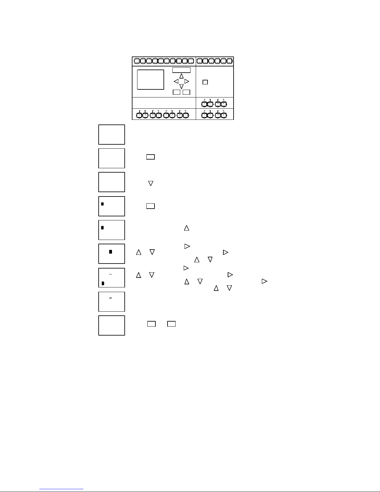
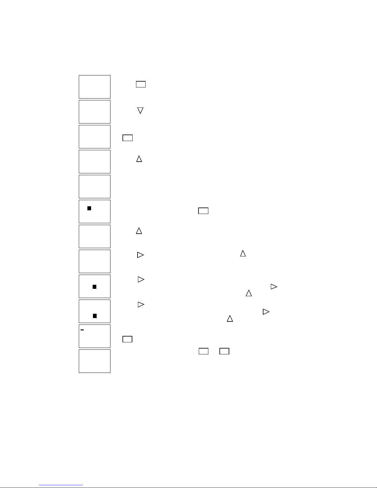
Setting the Day and Time
ESC
I6
AUX!
RUN/STOP
OK
2
Q4
1Q11Q22
Q4
221
1Q31 2
L N I2I1 I3 I4 I5 I7 I8 L N I2I1 I3 I4
Su 00:00
01.01.00
LOGO!
Q1 Q2
1 2
1 2Q31 2
Su 00:00
01.01.00
>Stop
Set Parma
Set Clock
Prg Name
Stop
Set Parma
>Set Clock
Prg Name
Set Clock
Su 00:00
MM.DD.YY
01. 01. 00
Set Clock
Th 00:00
MM.DD.YY
01. 01. 00
Set Clock
Th 00:00
MM.DD.YY
01. 01. 00
Set Clock
Su 06:16
MM.DD.YY
01. 01. 00
Set Clock
Su 06:16
MM.DD.YY
01. 06. 03
1. When power is first applied to the RPD10 panel the following display will blink
If the SERVICE FILTERS WITHIN 4 HOURS displays instead the OVERRIDE
switch is on. Just rotate the switch and the correct display will blink.
OK
2. Press and the following screen will appear.
3. Press twice.
4. Press and the following screen will appear.
OK
5. To change the day press
6. To change the time press once. The hour will be highlighted. Press
Adjust the minutes by pressing
7. To change the date press again. The month will be highlighted. Press
Adjust the day by pressing
move to year. Adjust the year by pressing
8. You have finished setting the clock.
until the correct hour appears.
or
until the correct month appears.
or
until the correct day appears.
Press to move to minutes.
or
until correct minutes appears.
Press to move to day.
until correct day appear. Press to
or
or
until correct year appears.
Su 06:16
01. 06. 03
Setting the clock on RPD10A automatic panels
OK ESC
7. Press and
to return to the operating screen.
Figure 22
Enviro Maintenance Manual 2004
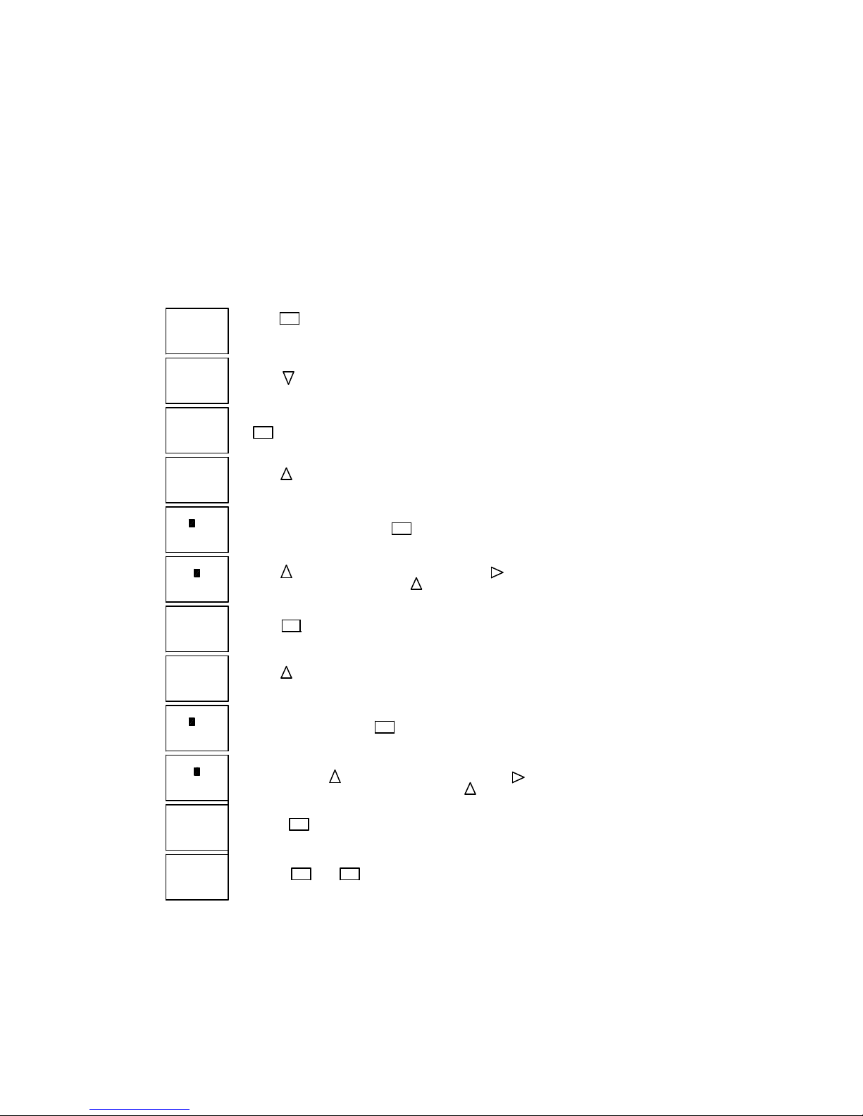
Setting the Weekend Fan "ON" and "OFF" times
Su 06:16
01. 06. 03
>Stop
Set Parma
Set Clock
Prg Name
Stop
>Set Parma
Set Clock
Prg Name
B04: No1
D =MTWTFSS
On = 06: 00
Off = 23: 00
B04: No1
D =MTWTFSS
On = 06: 00
Off = 23: 00
B04: No1
D =MTWTFSS
On = 06: 00
Off = 23: 00
B04: No1
D = MTWTF-S
On = 06: 00
Off = 23: 00
B04: No1
D = - TWTF- -
On = 06: 00
Off = 23: 00
1. Press
2. Press once.
3. Press
4. Press
5. The clock has been factory set to turn the fan on at 6:00 a.m. and off
6. To change the above settings press
7. Press to remove Monday from the weekly schedule. The - dash indicates
8. Press to move to the next day of the week. Press each time the fan is
ESC
OK
time setting for start and stop each weekday.
at 23:00 hours or 11:00 p.m.
the fan will not start automatically any given day.
not required to operate on that given day. The screen on the left indicates the
fan will not automatically operate on Monday, Saturday or Sunday.
until the B04: No1 timer appears. This is the
OK
The cursor will move to M = Monday.
B04: No1
D = - TWTF- -
On = 0 6: 00
Off = 23: 00
B04: No1
D = - TWTF- -
On = 06: 30
Off = 2 3: 00
B04: No1
D = MTWTF- -
On = 06: 30
Off = 22: 30
Su 06:16
01. 06. 03
9. Press to move to the hour that the fan will start in the morning. Press
to change the hour you want the fan to start in each morning. Press to move
to the minute the the fan will start in the morning. Press to change the minutes.
10. Press to move to the hour that the fan will stop in the evening. Press
to change the hour you want the fan to stop each evening. Press to move
to the minute the fan stop in the evening. Press to change the minutes.
11.Press
OK
12. If your selection is complete press and to return to the operating screen.
You have completed programming one weekly fan "On" and "Off" cycling. If you wish
to program a second (Weekend Operation) or third weekly setting go the the section
"Setting Weekend Operation"
ESC ESC
Setting the Week Day Fan On and Off Timers on RPD10A automatic panels
Figure 23
Enviro Maintenance Manual 2004

Setting Weekend Operation
Su 06:16
01. 06. 03
>Stop
Set Parma
Set Clock
Prg Name
Stop
>Set Parma
Set Clock
Prg Name
B04: No2
D = - - - - - - -
On = - - : - Off = - - : - -
B04: No2
D = - - - - - - -
On = - - : - Off = - - : - -
B04: No2
D = - - - - - SS
On = - - : - Off = - - : - -
B04: No2
D = - - - - - SS
On = - - : - Off = - - : - -
1. Press
2. Press once.
3. Press
4. Press
5. Press to program the weekend operation.
6. Press five times to move to Saturday. Press to turn fan on Saturday.
7. Press to move to the hour that the fan will start in the morning. Press
ESC
OK
until the B04: No1 timer appears. This is the
time setting for start and stop each weekday.
OK
Press once to move to Sunday. Press to turn fan on Sunday.
to change the hour you want the fan to start in each morning. Press to move
to the minute the the fan will start in the morning. Press to change the minutes.
B04: No2
D = - - - - - SS
On = 10: 00
Off = - - : - -
B04: No2
D = - - - - - SS
On = 10: 00
Off = 23: 30
Su 06:16
01. 06. 03
Setting the and Weekend Fan On and Off Timers on RPD10A automatic panels
8. Press to move to the hour that the fan will stop in the evening. Press
to change the hour you want the fan to stop each evening. Press to move
to the minute the fan stop in the evening. Press to change the minutes.
9. Press
operating screen.
10. You have completed programming weekend fan "On" and "Off" cycling.
If your selection is complete press and to return the
OK
ESC ESC
Figure 24
Enviro Maintenance Manual 2004

ODOR SPRAY SYSTEM
Operating and Maintenance
The Spring Air Systems Inc. odor spray unit has a one-year warranty from startup. The two timers, cyc le
timer B01, and spray timer B02, are factory set (5 minute cycle and 2 second spray) and then adjusted
during startup to the odor reducing intensity required for the application. The B01 cycle timer is generally set
between 5 to 10 minutes. The B02 spray timer is generally set between 2 to 60 seconds.
How does it Work?
The odor spray setting is a qualitative measurement. The spray timers are field set to provide adequate
odor reduction for the installation. This is completely subject to what a particular person feel is an
acceptable discharge odor.
During the spray timer activation the combination air compressor and air-atomizing nozzle injects a volume
of odor solution into the exhaust discharge. This solution is carried along the discharge duct and vented to
atmosphere. The spray solution chemically activates with the kitchen exhaust air to reduce the kitchen
exhaust odors. As the solution is carried down the duct some adheres to the duct walls. We will call this the
spray residue. During the cycle time when the spray is not activated this spray residue continues the odor
reducing process as the exhaust air passes. Therefore installation with longer discharge ducts can normally
use a longer cycle time because there will be more spray residue. A shorter run of discharge duct usually
results in shorter cycle time.
A. When adjusting the timers the object is to use as little spray solution as possible to provide adequate
odor reduction:
1. First adjust the spray cycle, B01 timer.
2. Reduce this setting by ½ of the original cycle setting and check the operation. If ½ proves
adequate, increase the cycle back to ¾ of the original cycle setting. If this is adequate increase to
7/8 of the original setting and so forth.
3. If reducing the setting by ½ is not adequate decrease the cycle to ¼ of the original setting. If this is
not adequate adjust the spray timer B02.
a. Increase the spray time B02 in increments of 5 seconds. After each 5 second increase
evaluate the quality of the exhaust discharge air to determine if it is acceptable to the user.
b. When the spray timer setting equals the cycle timer settings the spray will be continuous.
The maximum setting of B02 should not exceed the cycle timer B01.
The odor spray bottle must be changed regularly depending on the length of time set on timers B01 and
B02. The odor spray line from the spray bottle to the spray nozzle must be cleaned every 6 months in a
water and detergent mixture. The compressed air gauge should read between 10 and 15 psi. When the air
gauge is reading below 10 psi clean out the compressed air line. If the pressure is still low proceed to the
next step compressor maintenance.
When there is odor in adjoining floors or office spaces
A kitchen located in the interior of an office building must be very negative to keep the kitchen odor within
the kitchen. We recommend the kitchen be a minimum 20% negative. The fresh air supply is 80% of the
total exhaust air from the kitchen space. When there is odor in adjoining spaces check the following.
1. The kitchen is not negative enough to keep the smell of the kitchen in the kitchen. If this is the
case the odor is usually present all the time, even when there is no cooking. Reduce the amount of
fresh air to the kitchen by adjusting the supply fan volume.
2. The kitchen may be connected to the same building A/C unit as the rest of the floor. If this is the
case the return air grilles in the kitchen draws the kitchen odor to the main A/C unit and disperses
the odor throughout the floor. The main A/C return must be blocked from the kitchen and put on a
separate A/C unit.
3. The floor above the kitchen have odor. There are three possibilities.
a. The exhaust shaft is not sealed and the kitchen exhaust is leaking out onto the floors
above the kitchen. Either adjust the amount of odor spray per section "A" above or install
Enviro Maintenance Manual 2004
an exhaust fan on the roof to draw the kitchen exhaust to the roof and maintain a negative
pressure in the discharge duct.
b. The odor may escape when the kitchen is not operating during the night. After the kitchen
is shut off kitchen odor may migrate up the exhaust duct and leak out into the adjoining
floors. This can be solved by operating the kitchen exhaust for a couple hours after the
cooking has stopped for the day and starting the kitchen exhaust fan an hour before
cooking starts in the morning.
Setting the cycle and spray times
ESC
Su 06:16
01. 06. 03
>Stop
Set Parma
Set Clock
Prg Name
Stop
>Set Parma
Set Clock
Prg Name
B01: T
T = 05:00m
Ta = 05:00m
B01: T
T = 05:00m
Ta = 00:00m
B01: T
T = 05:00m
Ta = 00:00m
1. Press
2. Press once.
3. Press
OK
4. Press
or the time period between sprays.
5. To change the cycle time press
6. The first two digits are minutes and the two digits to the right are seconds.
Press to change the cycle length in minutes. Press to move to the
the cycle length in seconds. Press to change the seconds.
until the B01 timer appears. This is the cycle timer
OK
B01: T
T = 04:30m
Ta = 00:00m
B02: T
T = 03:00s
Ta = 00:00m
B02: T
T = 03:00s
Ta = 00:00s
B02: T
T = 03:00s
Ta = 00:00s
B02: T
T = 02:30s
Ta = 00:00s
Su 06:16
01. 06. 03
7. Press if the cycle time is correct.
8. Press
9. To change spray time press
10. The first two digits are seconds and the two digits to the right are 0.1 and 0.01
11. Press if the cycle time is correct.
12. Press and to return to the operating screen.
OK
or the length of the odor sprays.
the spray time in fractions of a second. Press to change the 0.1 and 0.01 seconds.
until the B02 timer appears. This is the spray timer
OK
seconds. Press to change the spray in seconds. Press to move to the
OK
ESC
ESC
Setting the Cycle and Spray Timer
Figure 25
Enviro Maintenance Manual 2004
Compressor Maintenance
WARNING
-
Do not, at any time lubricate any of the parts with oil, grease, or petroleum products nor clean with acids,
caustics or chlorinated solvents. Be very careful to keep the diaphragm from contacting any petroleum
product of hydrocarbons. It can affect the service life of the pump.
To clean or replace the filters and/or rubber gasket, remove the five screws in the top of the unit. The filters
and gaskets are located beneath this top plate. Remove the filters and wash then in a solvent and/or blow
off with air and replace. The gasket may be cleaned with water. Replace the filters in proper position and
replace the gasket. Note that the gasket and top plate will fit in one position only.
To replace the diaphragm, remove the socket cap screws from the head of the pump. The diaphragm is
held in place by two Philip head screws. Remove screws, retainer plate, and diaphragm. The diaphragm
will fit in any position on the connecting rod. Replace the plate and the two Phillips head screws. Torque to
30 inch-pounds on DOA and DAA.
Caution: Do not raise any burrs or nicks on the heads of these screws. These burrs could cause damage
to the inlet valve.
For replacing the inlet and outlet valve, remove the slotted machine screw that holds each valve in place.
The stainless steel inlet and outlet valves are interchangeable. Clean them with water. When replacing the
outlet valve, place the new valve in location and note there is a retaining bar near the machine screw hole.
This retaining bar holds the valve in position. When replacing the inlet valve, note that the valve holder is
marked with an X in one corner. This X should be in the lower right hand corner toward the inlet of the air
chamber. Replace the head and tighten the socket head screws to 90-100 inch-pounds or torque on DOA
and DAA.
The motor is
thermally
protected
and can
automaticall
y restart
when the
protector
resets.
ALWAYS
disconnect
KES fan
power
source
before
servicing.
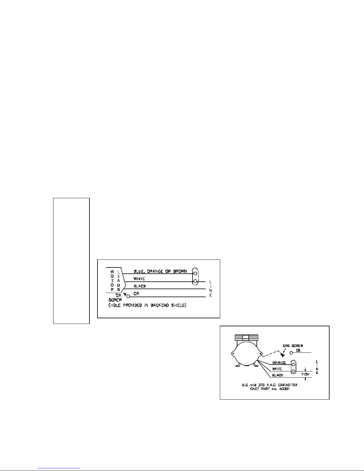
For any permanent split capacitor for DOA & DAA motor,
which has three (3) leads is as follows:
Do not attempt to replace the connecting rod or motor bearings. If after cleaning the unit
and/or installing a new service kit, the unit still does not operate properly, contact your
representative, the factory, or return the pump to one of our authorized Service Centers.
IF YOUR PUMP IS EQUIPPED WITH PLASTIC PLUGS IN THE EXHAUST AND/OR
INTAKE POTS, REMOVE BEFORE STARTING THE UNIT
Wiring Information
For any permanent split
capacitor motor, which has four
(4) leads is as follows:
Brown leads to capacitor.
Black-leads to Power Source.
IMPORTANT NOTICE:
DO NOT AT ANY TIME ATTEMPT TO REMOVE THE CONNECTING ROD
OR COMPLETELY DISASSEMBLE THE PUMP. IF IT DOES NOT GIVE
YOU THE PROPER SERVICE EVEN AFTER INSTALLING A NEW
SERVICE KIT, PLEASE RETURN IT TO ONE OF THE AUTHORIZED
SERVICE CENTERS
Enviro Maintenance Manual 2004

WHERE TO PURCHASE FILTERS:
Spring Air Systems Inc.
1388 Cornwall Rd., Oakville Ont., L6J 7W5
(905) 338-2999
Airguard Industries
125 Buttermill Rd., Concord, Ontario, L4K 3X5
905-669-9876
Airguard Corp.
4806 Strong Rd., Crystal Lake, IL, 60014
888-324-5665
Camfil Farr Filters
67 Steelecase Rd. W., Markham Ont., L3R 2M4
RECOMMENDATION
TO ENSURE TROUBLE FREE OPERATION FOR
YOUR KITCHEN EXHAUST SYSTEM A PROPER
PREVENTATIVE MAINTENANCE PROGRAM IS A
NECESSITY.
SPRING AIR SYSTEMS RECOMMENDS THAT A
YEARLY SERVICE CONTRACT BE SET UP WITH A
REPUTABLE SERVICE ORGANIZATION. THIS WILL
REDUCE UNEXPECTED DOWN TIME TO A MINIMUM.
(905) 415-3030
Camfil Farr
2201 Park Place, El Segundo, CA, 90245
310-727-6300
REPLACEMENT FILTER EQUIVALENTS
PREFILTERS: 30% ASHRAE 52-76 - ULC Class II
Airguard: 24” x 24” x 2” - DP40 Class II
12” x 24” x 2” - DP40 Class II
American Air Filter:
24” x 24” x 2” - AM-AIR Class II
12” x 24” x 2” - AM-AIR Class II
Farr Filters: 24” x 24” x 2” - 30% ASHRAE 52-76 Class II
12” x 24” x 2” - 30% ASHRAE 52-76 Class II
BAG FILTERS: 90 - 95% ASHRAE 52 - 76 - ULC Class II
Airguard: 24” x 24” x 22” - V9-4M Class II
12” x 24” x 22” - V9-4M Class II
American Air Filter:
24” x 24” x 21” - DRI-PAK - Class II
12” x 24” x 21” - DRI-PAK - Class II
Farr Filters: 24” x 24” x 22” - 90% ASHRAE 52-76 Class II
12” x 24” x 22” - 90% ASHRAE 52-76 Class II
BOX FILTERS: 95% DOP/99% ASHRAE 52-76 ULC Class II
Airguard: 24” x 24” x 12” - VMB- 904 Class II
12” x 24” x 12” - VMB-904 Class II
American Air Filter:
24” x 24” x 12” - BIOCELL Class II
12” x 24” x 12” - BIOCELL Class II
Farr Filter:
24” x 24” x 12” - 6 pocket - 95% DOP Class II
12” x 24” x 12” - 6 pocket - 95% DOP Class II
ODOR MEDIA: 1/8” Activated alumina pellets impregnated with potassium permanganate.
Airguard: Barneby-Cheney CP-2
American Air Filter:
Permasorb
Farr Filters: Unisorb.
Odor Spray: Spring Fresh, Spring Air Systems
Enviro Maintenance Manual 2004

TROUBLE SHOOTING
I. Exhaust fan does not run.
Reset the system once. Press the reset button in the LV10 J-Box or turn the fan selector switch
to “OFF” and “ON”. Observe the sequence that follows.
1.The fan does not start and there is no indication on remote panel.
a)Check power from the breaker to the RPD10.
b)Check the three wiring connection from the wash panel to the RPW10 panel.
2.The fan does not start but the green normal pilot energizes for 30 seconds goes
out and “Filter removed” pilot energizes.
a)Check wiring between KES filter box LV10 J-box terminals 5 & 4 and the KESF fan motor
starter.
b)Check wiring between the RPD10 or RPW10 remote and the KES-ISH LV10 J-Box
c)Reset the exhaust fan overload in the exhaust fan motor starter on the KESF fan section.
d)Check three phase power to the KESF fan section disconnect.
e)Check if exhaust duct access door is open between the KES filter section and hood.
f)Check that all filters on in place.
g)Check if the prefilter or box filter access door on the KES unit is open
h)Check the Filter Removed pressure switch. The switch must make and close after 30
seconds of operation. Adjust the pressure setting or replace switch.
i)If all the filters are in place check if pressure tips on the end of the pressure switch
manifolds are plugged. There is a pressure tip in front and behind each filter.
j)Measure Exhaust air volume. If low increase fan RPM to within FLA of fan motor
k)Check KESF exhaust fan motor starter coil. Replace or repair.
l)Check KESF fan belts if loose or broken.
m)Check KESF exhaust fan motor. Replace or repair.
3.The exhaust fan runs for 30 seconds then shuts off and one of the Filter
Clogged pilots energizes.
a.Check the wiring from the LV10-J-Box to the pressure switch
b.Check pressure switch operation P1, P2 & P3. These switches should remain open after
30 seconds operation. Calibrate the pressure setting or replaced switch.
c.Check the wiring between the RPD10 or RPW10 panel and the LV10 J-Box.
II. Low Exhaust Air
1.Exhaust fan is running but exhaust air is low.
a)Check if fan belts are slipping. Tighten if necessary.
b)Check if fusible link fire damper has closed in the KES filter section. Replace fusible link.
c)Check if filters are dirty but have not activated the “Filter Clogged” pilot. Replace dirty
filters.
d)Check for correct fan rotation.
Enviro Maintenance Manual 2004

III. Filter Clogged Pilot On.
1.Filter clogged pilot indicates which filter section has plugged. Replace filter and reset
system.
IV. Filter Removed Pilot On.
1.A filter has been removed or access door left open. Replace if necessary.
V. Fire Pilot On.
1.The fire stat in the KES filter section exhaust outlet has activated and shut the KES system
down. If a fire is not present check calibration of firestat TH1. Firestat should be set at
160F.
If operation problems persist check the individual the connection between the RPD10 or RPW10
panel and the LV10 J-Box. If problems still exist contact an authorized SPRING AIR SYSTEMS
service technician.
Enviro Maintenance Manual 2004

KES MAINTENANCE SCHEDULE
Every two weeks:
1.Inspect the prefilters. Replace if necessary. It is important to maintain clean
prefilters. Replacing the inexpensive prefilters often extends the life of the bag
and box filters and reduces unnecessary down time due to clogged filter
shutdowns. The RPD or RPW annunciation panel will indicate separately when
the “prefilter”, “bag” and “box” filters are clogged. When this occurs the unit
shuts down. Rotate the override switch to energize the system for about 4 hours.
This provides time to change the filters after the day of cooking. This is a final
dirty filter warning. The filter life of all the filters is constant for each operation.
Once the approximate filter life for your application is determined we recommend
that a regular filter change schedule be set up before the filter out switches
activate.
Every Month:
1.Complete the two -week list.
2.Inspect the exhaust fan belt for correct tension and wear. All belts usually require
adjustment at this time. Failure to tighten may result in the belt falling off and no
airflow.
3.Inspect the bag filters (2nd stage filtration). Replace if necessary. The life of the
bag filter depends on the type of cooking equipment and exhaust hood system.
For heavy cooking applications the bag filters may require replacement every
month.
4.(Odor Spray Option) Inspect the odor spray bottle. Refill if necessary. At startup
the odor spray is adjusted to the desired level. The amount of odor spray used
varies with this initial setting. It is important to inspect the level in the bottle every
two weeks until the normal rate of use is determined.
Every Three Months:
1.Complete the two -week and monthly checklist.
2.Inspect the exhaust fan belt for correct tension and wear. Adjust if necessary.
3.Inspect the box filters (3rd stage filtration). Replace if necessary. Once again the
life of the box filter depends on the type of cooking equipment and exhaust hood
system. The box filter may provide one year of service on most applications with
high efficiency water wash ventilators.
4.Inspect all electrical connections. Tighten if necessary.
5.Test the filter-removed circuit. Open the prefilter access door while the KES unit is
in operation. The unit should shut down and indicate a filter-removed condition.
Every Six Months
1.Complete the two -week, monthly and three month check list.
2.Open the fan wheel access door or hatch on the KES fan section. Inspect the fan
wheel for grease build up. Clean as required.
3.Inspect the exhaust inlet fire damper and fusible link. Replace link annually.
4.Check the motor and fan bearings for noise or overheating.
5.(Odor Pellet Option) Inspect the condition of odor media.
Enviro Maintenance Manual 2004

6.The odor media pellets can be checked for remaining life by sending a sample to
an accredited test laboratory. Most major filter suppliers have access to such
service. Replace media if required. To replace the media remove the cells from
the KES unit. Open the side panel on each odor cell and pour out the used
media. Refill the cells with new media. Shake cells while filling to allow pellets to
settle evenly in the cell. Note: Do not allow odor media to come in contact with
water, as this will immediately render the pellets useless.
Fan Bearings
1.STY and FYC bearings are factory pre-lubricated lifetime sealed and require no
further lubrication.
2.SY and FY bearings are pre-lubricated and equipped with pressure grease fittings
for re-greasing.
3.Under normal service conditions grease after six months of operation.
Motor Bearings:
1.All motors leave the factory with bearings custom greased for many years of
service under most conditions.
2.Re-greasing of motors depends on the application and is best left to trained service
technicians.
3.Periodically check if motor is running hotter then normal.
Centrifugal Exhaust Fan:
1.Make sure the wheel rotates freely before startup.
2.Inspect and clean the wheel periodically.
3.If dirt is allowed to build up the wheel could become out of balance and cause
premature bearing wear.
4.A noisy fan is a typical sign of a fan out of balance.
V-Belt Drives:
1.ALWAYS KEEP SPARE SET OF BELTS. Periodically check the belt tension and
adjust if necessary.
2.Some slack should be left in the belt, typically 1/4” per foot of belt from the fan to
the motor sheave.
3.Always replace the complete set of belts to ensure even tension and wear. When
replacing belts loosen the motor mounts.
4.Do not force belts over sheaves.
RECOMMENDATION
TO ENSURE TROUBLE FREE OPERATION FOR YOUR KITCHEN EXHAUST
SYSTEM A PROPER PREVENTATIVE MAINTENANCE PROGRAM IS NECESSARY.
SPRING AIR RECOMMENDS THAT A YEARLY SERVICE CONTRACT BE SET UP
WITH A REPUTABLE SERVICE ORGANIZATION. THIS WILL REDUCE
UNEXPECTED DOWN TIME TO A MINIMUM.
Enviro Maintenance Manual 2004

KES ENVIRO START-UP REPORT
96
-
Turn on the Override switch in the RPD10 or RPW10 remote panel. The LOGO text message “Service
” switch in the wash panel or remote RPD10 panel to the OFF position. Observe the fan
RPD10 or RPW10 to the original position. The text message will
Job Name Date
Location File No.
KES No. Motor HP
S/N Voltage
Item Description Y / N
1
2
2a
3
4
5
6
7
Check if all filters are in the unit
Type of Filter Size Qty
8
9
10
11
12
13
Check all electrical connections. Tighten as necessary
(RPD10 panels only) Check for power to the RPD10 panel on terminals 1 & 4
Check all remote wiring to ensure it has been connected
(RPW10 panels only) Check wiring to terminals 1, 3 & 4 from water wash panel to RPW10 remote
LV10 J-Box wiring to terminal 1, 4 & 5 from RPD10- or RPW10 remote
LV10 J-Box wiring to terminal 4 & 5 to exhaust fan motor starter
LV10 J-Box wiring to odor spray 4 & 17 (Optional for odor spray units)
Power wiring to disconnect switch
Prefilter 12” x 24” x 2”
Prefilter 24” x 24” x 2”
Bag Filter 12” x 24” x 22”
Bag Filter 24” x 24” x 22”
Box Filter 12” x 24” x 12”
Box Filter 24” x 24” x 12”
Item Decryption Y / N
14
15
16
17
Check of the inlet exhaust ductwork to the KES unit from the kitchen exhaust hood is all welded NFPACheck if clearance to top, sides, and ends of KES filter box is available: 18” to combustible or 6” to non
combustibles
Check power at disconnect switch 3/60/ V
Check fan rotation as follows:
Turn on the main disconnect to the KESF fan motor starter
Turn “FAN ON” switch in the wash panel or remote RPD10 panel to the ON position
Filters within 4 hours” will appear.
Turn “FAN OFF
rotation. Change one of L1, L2 or L3 if fan is rotating backwards
Item Description Y / N
18
19
20
Safety Circuit Check
21
22
23
24
Switch P1
25
26
27
28
Switch P2
29
30
31
32
Switch P3
33
34
35
36
Turn “FAN ON” switch in the wash panel or remote RPD10 panel to the ON position
Check the FLA L1 L2 L3
Adjust the overload setting on motor starter to FLA rating of motor
Turn “FAN OFF” switch in the wash panel or remote RPD10 panel to the OFF position
Rotate the OVERRIDE switch on the
disappear once the fan is turned back on.
Remove the front covers from all the pressure switches on the KES-ISH filter box.
Turn “FAN ON” switch in the wash panel or remote RPD10 panel to the ON position
Jumper switch P1– terminals 1 & 12
KES unit shuts off Yes No
Prefilter clogged light on and LOGO text message “Change Prefilter” Yes No
Reset unit at LV10 J-Box reset switch by turning on and off
Jumper switch P2– terminals 1 & 13
KES unit shuts off Yes No
Bag clogged light on and LOGO text message “Change Bag filter” Yes No
Reset unit at LV10 J-Box reset switch by turning on and off
Jumper switch P3– terminals 1 & 14
KES unit shuts off Yes No
Box clogged light on and LOGO text message “Change Box Filter” Yes No
Reset unit at LV10 J-Box reset switch by turning on and off
Enviro Maintenance Manual 2004

KES ENVIRO STARTUP REPORT page 2
Filter removed light on and LOGO text message “Filter Out or Low Exhaust”
GO text message “Filter Out or Low Exhaust”
Replace pressure switch covers and turn of the unit and remove all the bag filters. Shut the access door and turn the
Filter removed light on and LOGO text message “Filter Out or Low Exhaust”
vers and turn of the unit and remove all the box filters. Shut the access door and turn the
Filter removed light on and LOGO text message “Filter Out or Low Exhaust”
If the unit does not shut off and the filter clogged light does not come on for this test the pressure switch setting must
he LOGO text message “Prefilter Clogged”
Warning light turns on and the LOGO text message “Service Filters within 4
or RPD10 remote panel to the OFF position. The Warning light goes off
Switch P4
33
34
35
36
Switch P5
33
34
35
36
Filter Out Test #1
33
34
35
36
Filter Out Test #2
37
38
39
40
Fire Switch Test
41
42
43
44
Check override switch
45
46
47
48
49
50
51
52
53
54
55
56
Jumper switch P4
KES unit shuts off Yes No
Reset unit at LV10 J-Box reset switch by turning on and off
Jumper switch P5
KES unit shuts off Yes No
Filter removed light on and LO
Reset unit at LV10 J-Box reset switch by turning on and off
unit on. Wait for 30 sec.
KES unit shuts off Yes No
Reset unit at LV10 J-Box reset switch by turning on and off
Replace pressure switch co
unit on. Wait for 30 sec.
KES unit shuts off Yes No
Reset unit at LV10 J-Box reset switch by turning on and off
be adjusted. With the filters out rotate the pressure adjustment screw slowly clock wise until the unit shuts off.
Jumper terminals 1 & 16 in the LV10 J-Box.
KES unit shuts off Yes No
Fire light on Yes No
Reset unit at LV10 J-Box reset switch by turning on and off
Turn “FAN OFF” switch in the wash panel or remote RPD10 panel to the OFF position
Jumper terminals 1 & 12
Turn “FAN ON” switch in the wash panel or remote RPD10 panel to the ON position
After 30 seconds the KES shuts off, the Prefilter Clogged light turns on and t
will appear.
Rotate the OVERRIDE switch on the RPW10 or RPD10 remote panel to the ON position.
KES unit turns on Yes No
hours” will appear.
Turn “FAN OFF” switch in the wash panel or remote RPD10 panel to the OFF position
Remove the jumper
Turn “FAN ON” switch in the wash panel or remote RPD10 panel to the ON position
Rotate the OVERRIDE switch on the RPW10
and the LOGO text message disappears.
Measure the exhaust air volume at each hood
Use hood start up form for this
Yes No
Yes No
Yes No
Yes No
Yes No
Comments:
Service Technician:_____________________________________________________________
Yes I have received a set of Spring Air Systems Inc. maintenance manuals.
Signature ___________________ Print Name ____________________
Enviro Maintenance Manual 2004

FILTER FREQUENCY CHART
Enter the date of each filter change
Startup date
Change No. Prefilter Bag Filter Box Filter Odor
1
2
3
4
5
6
7
8
9
10
11
12
13
14
15
16
17
18
19
20
21
22
23
24
25
26
27
28
Enviro Maintenance Manual 2004

Other Fine Products From
SPRING AIR SYSTEMS...
Water Wash Ventilators
•Hot Water Wash
•Cold Water Spray/Hot Water Wash
•Water Wash Control Panels
Dry Ventilators
REV-LOW Hood
Filter Hoods
Surface Fire Suppression
Commercial Kitchen Exhaust Fans
Kitchen Enviro Systems
•KES - 100% Exhaust
Commercial Kitchen Supply Units
Bio Spray Hoods
Compensating Hoods
 Loading...