

Spring Air Systems Dynaflow, Dynaflow FN-B-MB, Dynaflow Series, Dynaflow FN-B-MJ Installation And Maintenance Manual

Dynaflow
Hood
Installation and Maintenance
Manual
___________________________
Spring Air Systems Inc., Oakville, Ontario
Phone (905) 338-2999, Fax (905) 338-0179, info@springairsystems.com
2010 Revision 1.0

Dynaflow Installation and Maintenance
Manual
Table of Contents
Introduction 1
Spring Air Systems Hood Model Number Designations 2
Dynaflow MB Hood Principle of Operation 2
Three Fresh Air Boundary Regions 3
Standard Dynaflow MB hood specification 3
Dynaflow MJ Hood Principle of Operation 4
Standard Dynaflow MJ hood specification 5
Dynaflow Installation 5
Arrangement “D” Exhaust Fire Damper Assemblies 7
Link/Cable Assemblies for various exhaust duct collar sizes. 7
Adjusting the Fire Damper Blade Position 9
Grease Filter for Dynaflow Hoods 10
MJ Blower assembly for all MJ hoods 13
Dynaflow Maintenance Schedule 14
Trouble Shooting and Cleaning 15
Measuring Exhaust Air flow with VE, HE, EC and Sa Filters 16
Measure Exhaust Air Flow with CA Filters 20
Measuring Dynaflow MB Supply 22
A. Measuring the Appliance Region 22
B. Adjusting the MB Blade to change velocity at the appliance region. 23
C. Adjusting the air velocity to the Chef Region. 23
C. Measuring the Supply Discharge velocity from the MB Blade. 23
Measuring Dynaflow MJ Plenum Air 25
A. Measuring the Appliance Region 25
B. Adjusting the MJ Blower to change the appliance region velocity 26
C. Adjusting the air velocity to the Chef Region 26
T
Dynaflow Hood Installation and Maintenance Manual
INTRODUCTION
Thank you for selecting a SPRING AIR SYSTEMS INC. Dynaflow commercial kitchen exhaust hood. The Dynaflow
hood is an innovative idea in commercial kitchen ventilator design that provides for the total kitchen comfort, particulate
capture and energy efficiency.
People comfort. The fresh air introduced through the make up air plenum utilizes the Comfort Tuning Blade to provide
a comforting breeze for the people working under the kitchen hood.
Balanced air flow design: The kitchen hood exhaust air and fresh air introduced into the kitchen space are always
balanced, reducing drafts, hot and cold spots and improving particulate capture.
Low exhaust volumes: The exhaust volume is minimized with dynaflow technology to maximize your energy
savings.
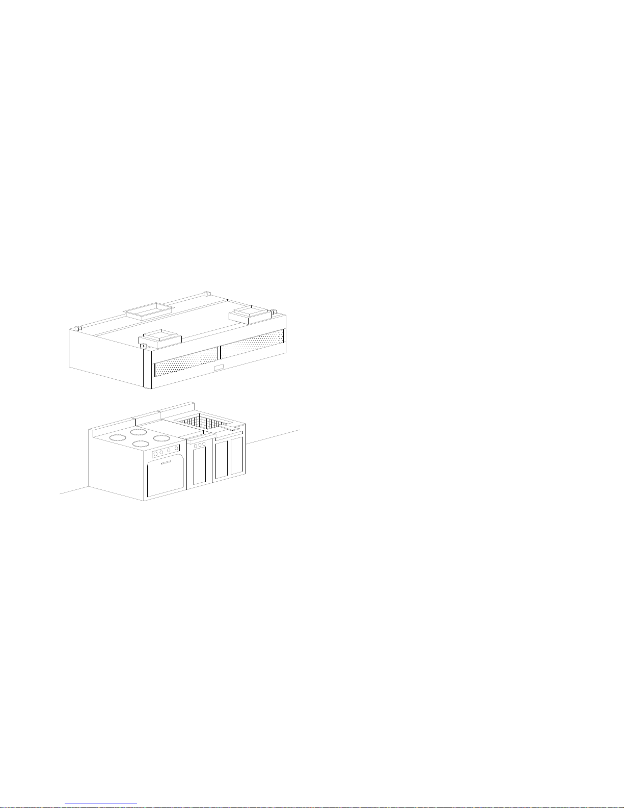
The Spring Air Systems Inc. Dynaflow hood was
selected to best meet the design requirements of
your commercial kitchen application.
The Dynaflow hood is a NFPA-96 Type 1 listed for
use with all temperature ranges on single row; wall
mounted, island double row cooking or island
single row cooking equipment lineups, The hood is
MAXIMUM 87"
MOUNTING HEIGH
Typical Dynaflow FN-B-MB Hood
Figure 1
• VE - standard grease extraction efficiency Stainless steel baffles.
• CA - Medium grease extraction efficiency cartridges with adjustable flow baffles.
• HE - High grease extraction Efficiency Cascade baffles for Enviro applications and reducing grease discharge
from buildings.
• EC - Easy Clean Teflon – standard grease extraction efficiency baffles for hot, heavy grease laden appliances.
• SA - Spark Arrestor – standard grease extraction efficiency, for solid fuel appliances.
ceiling hung with a maximum mounting height of
87” (2209 mm) from the lower front edge of the
canopy to the floor and (52” (1320mm) from the
surface of the cooking equipment to the lower edge
of the grease extractor). The box canopy can be
tapered to 11” (279 mm) at the front. The hood is
finished with a number 4 finish on exposed sides.
The Dynaflow hood is available with fluorescent,
incandescent, recessed incandescent or LED lights
wired to a J-box.
The Dynaflow hood is equipped with UL/ULC listed
grease filters or cartridges. Five extraction types are
available with Dynaflow.
1

Model Number Designation
Sample Model Number
F N B MB (VE)
F= Filter Hood
N= Exhaust duct collar with no fire damper, listed under
D= Exhaust duct collar with fusible link fire damper
B = box canopy
DS= double box canopy single row appliance
DB= double box canopy double row appliance
MB= Dynaflow type hood with Tri-Zone control System
MJ= Dynaflow type hood with Perimeter Defense control System
VE= standard grease extraction efficiency Stainless steel baffles.
CA= Medium grease extraction efficiency cartridges with adjustable flow baffles.
HE= High grease extraction Efficiency Cascade baffles for Enviro applications and reducing grease
discharge from buildings.
EC= Easy Clean Teflon – standard grease extraction efficiency baffles for hot, heavy grease laden
appliances.
SA= Spark Arrestor – standard grease extraction efficiency, for solid fuel appliances.
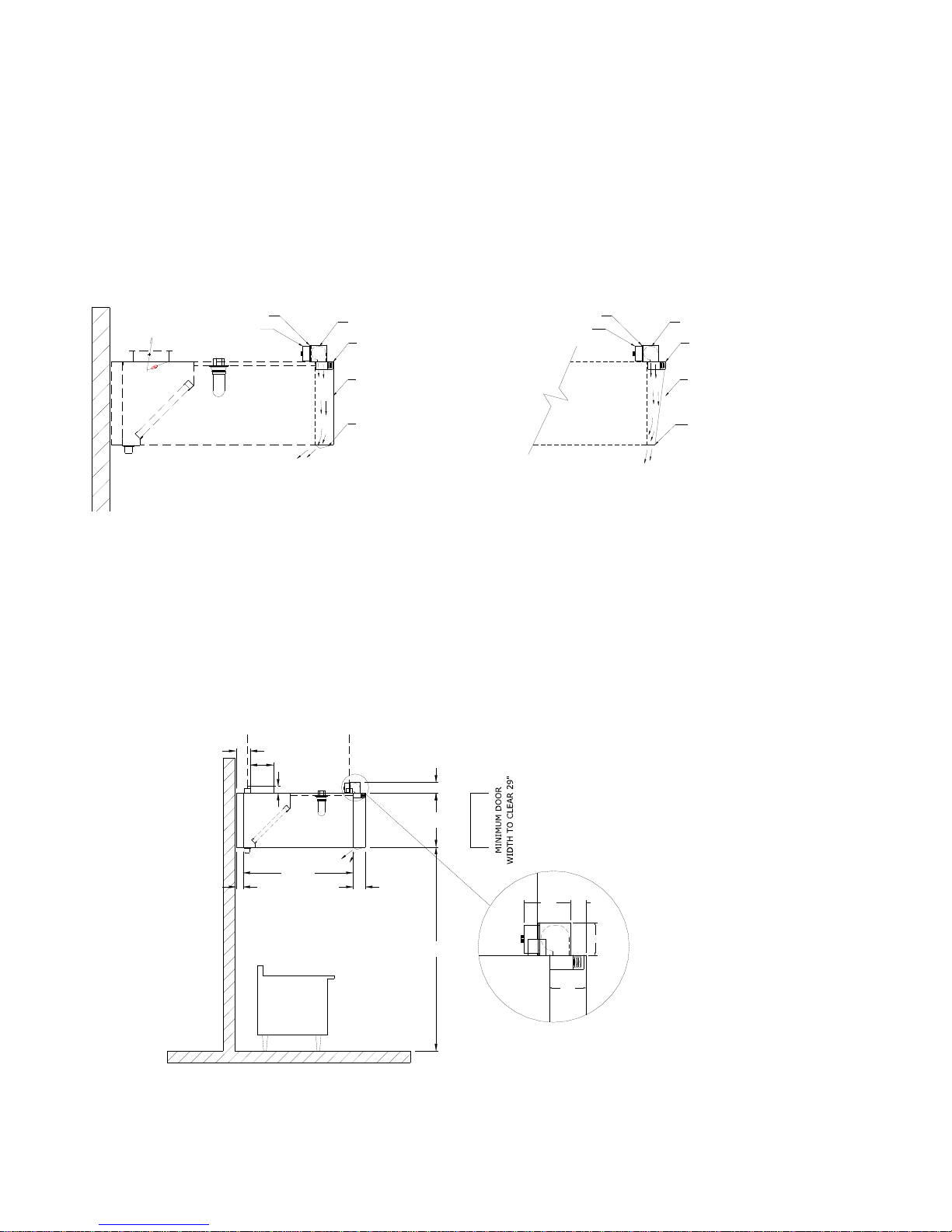
Dynaflow MB hood
8.00
6.00
3.00
2.00
1
54.00
5.25
APPLIANCE
2
5.50
3
23.00
MAXIMUM
87"
MINIMUM DOOR
WIDTH TO CLEAR 27"
Dynaflow FN-B-MB Hood Section
View with standard VE filters.
Figure 2
Principle of Operation
The Dynaflow design provides the lowest minimum exhaust. The Dynaflow hood exhaust volume is based on the
appliances below the hood. It’s a simple adjustment to fine-tune your ventilator to provide excellent smoke capture with
maximum grease extraction.
2

Fig
Heated and/or cooled fresh air ducting is connected to the supply duct collar(s) on the top, front of the hood. The fresh air
enters the fire damper in each supply duct connection and then discharges into the Dynaflow plenum. Within the plenum
the fresh air is routed to three (3) regions within the boundaries of the appliances.
Three Fresh Air Boundary Regions
1. Appliance Region: Fresh air discharges down through a full length S/S perforated panel, creating an air curtain
around the perimeter of the hood within the boundary of the kitchen appliances for excellent smoke capture with
maximum grease extraction and to reduce each appliance net exhaust requirement.
2. Chef Region: Fresh air discharges down through a full length S/S perforated panel towards the chef for a more
comfortable work environment in front of the hood.
3. Kitchen Ambient Region: The horizontal fresh air discharges through a s/s perforated panel out the front of the hood
into the kitchen to provide the exact amount of air to balance the kitchen and ensure optimum capture
HOOD CANOPY
END VIEW
Internal Blade (IB)
Comfort Tuning Blade(CTB)
BLADE FULL OPEN
1 Appliance Region Chef Region2 Kitchen Ambient Region3
3
HOOD CANOPY
END VIEW
BLADE FULL CLOSED
12 21
3
HOOD CANOPY
END VIEW
BLADE HALF OPEN
3
21
Fresh Air Regions
ure 3
The internal blade (IB) is adjusted to direct fresh air between the Kitchen Ambient (3) Region, the Appliance (1) Region,
and Chef (2) Region. The Comfort Tuning Blade (CTB) is adjusted to direct fresh air between the Appliance (1) Region
and the Chef (2) Region. The complete kitchen ventilation system is always balanced. The IB and CTB are adjustable
every 24” (610mm) along the length of the Dynaflow hood to match the appliances underneath. Dynaflow operates with
the lowest minimum exhaust. After your kitchen is complete, appliances can be Relocated, Added, or Removed from
under the hood while maintaining maximum capture and chef comfort within the commercial kitchen.
Standard Dynaflow MB hood Specification
The unit casing shall be a minimum 18 GA. stainless steel, with No. 4 finish on all exposed surfaces. The hood shall include UL/ULC
listed grease filters mounted in an integral stainless steel rack inclined at 45 degrees. The filter rack shall include a full length stainless
steel grease gutter and grease cup.
The optional exhaust fire damper shall be an arrangement "D", butterfly type, constructed of stainless steel with blade and edge seals.
The fire damper shall be activated by a fusible link and dead weight arrangement.
The Dynaflow plenum provides all the fresh air required for the commercial kitchen. The fresh air is routed to three (3) regions within
the boundaries of the appliances. Each region includes an aerodynamically designed s/s perforated discharge panel.
The first (1) region discharges through a full length s/s panel located at the bottom of the Dynaflow plenum. Fresh air is directed through
the Comfort Tuning Blade (CTB) towards the appliances providing maximum exhaust air reduction. The second (2) Region discharges
through a full length s/s angular panel located at the bottom front of the Dynaflow plenum. The fresh air is directed towards the chef to
provide a more comfortable work environment in front of the hood. The third (3) region provides horizontal discharge of fresh air
through a s/s perforated panel out the front of the hood into the kitchen. The third region provides the exact amount of fresh air to
balance the kitchen and ensure optimum capture.
The s/s front discharge shall include multiple s/s perforated panels for the full length of the hood. A manually operated Internal Blade
(IB) damper shall be located behind each front s/s discharge panel. The CTB and IB dampers are field adjustable through the lower s/s
discharge panel. The hood shall have ______ incandescent/fluorescent/recessed/incandescent/LED lights evenly spaced along the length
of the hood. Optional Sideflow right and/or left MJ blower assemblies are available.
3
Fig
Fig
Dynaflow MJ hood
Principle of Operation
The MJ Perimeter Defense design exhaust volume is based on the appliances under the hood. It’s a simple calculation to
determine your best exhaust volume for any commercial kitchen lineup. The MJ Perimeter Defense hood can be fine-tuned
to provide excellent smoke capture with maximum grease extraction. A MJ tangential blower is mounted on top of the
plenum. Return air from the ceiling is drawn into the blower inlet through removable washable aluminum mesh filters.
The tangential MJ blower discharges air through a fusible link fire damper into the MJ plenum. The air is then discharged
from the bottom through a two way adjustable perforated grill. The air is then proportioned between the appliances and the
chef aria by adjusting the comfort tuning dial. This is not fresh air from outside the building. Fresh supply air must still be
introduced somewhere else in the commercial kitchen.
MESH FILTERS
RHEOSTAT
MJ BLOWER
FIRE DAMPER
MESH FILTERS
RHEOSTAT
MJ BLOWER
FIRE DAMPER
SIDEFLOW
MJ PLENUM
S/S PERFORATED
DISCHARGE
HOOD CANOPY
END VIEW
INTERNAL APPLIANCE DISCHARGE
FRONTFLOW
MJ PLENUM
S/S PERFORATED
DISCHARGE
HOOD CANOPY
FRONT RIGHT VIEW
SIDEFLOW DISCHARGE
MJ Perimeter Defense Operation
ure 4
Introducing supply air back into the kitchen is good engineering practice. An adequate supply of fresh air eliminates cold
drafts, and hot spots, enhances the capture capability of the hood and results in a more comfortable kitchen environment. A
supply air volume of at least 80% of the total exhaust is recommended. The fresh air should be tempered to between 55 and
75F (13 to 24C). Direct the fresh air to separate diffusers surrounding the hood located in the finished ceiling. The diffusers
must be located to eliminate short circuiting the exhaust and drafting. Consult with factory for recommended kitchen
diffuser locations. If the hood is required to supply the fresh air directly refer to the Spring Air MB DYNAFLOW
specification sheet
6.00
10.00
3.00
4.63
23.00
3.00
47.00
APPLIANCE
Dynaflow FN-B-MJ Hood Section View with standard VE filters.
5.25
87.00
ure 5
6.63
2.25
4.63
5.25
4
Fig
7
Fig
Standard
Dynaflow MJ hood Specification
The unit casing shall be a minimum 18 GA. stainless steel, with No. 4 finish on all exposed surfaces. The hood shall include UL/ULC
listed grease filters mounted in an integral stainless steel rack inclined at 45 degrees. The filter rack shall include a full length stainless
steel grease gutter and grease cup.
The MJ blowers provides ceiling return air to the MJ plenum which discharges out the bottom of the plenum through a s/s perforated
plate along the length of the MJ plenum. The return air is directed through the MJ plenum towards the appliances. MJ blower(s) mounted
on top of the plenum shall be complete with adjustable Triacs, washable filters and wired to a common J-box on top of the hood. A
fusible link fire damper is located below each MJ blower.
The hood shall have ______ incandescent/fluorescent/recessed/incandescent/LED lights evenly spaced along the length of the hood.
Optional Sideflow right and/or left MJ blower assemblies are available.
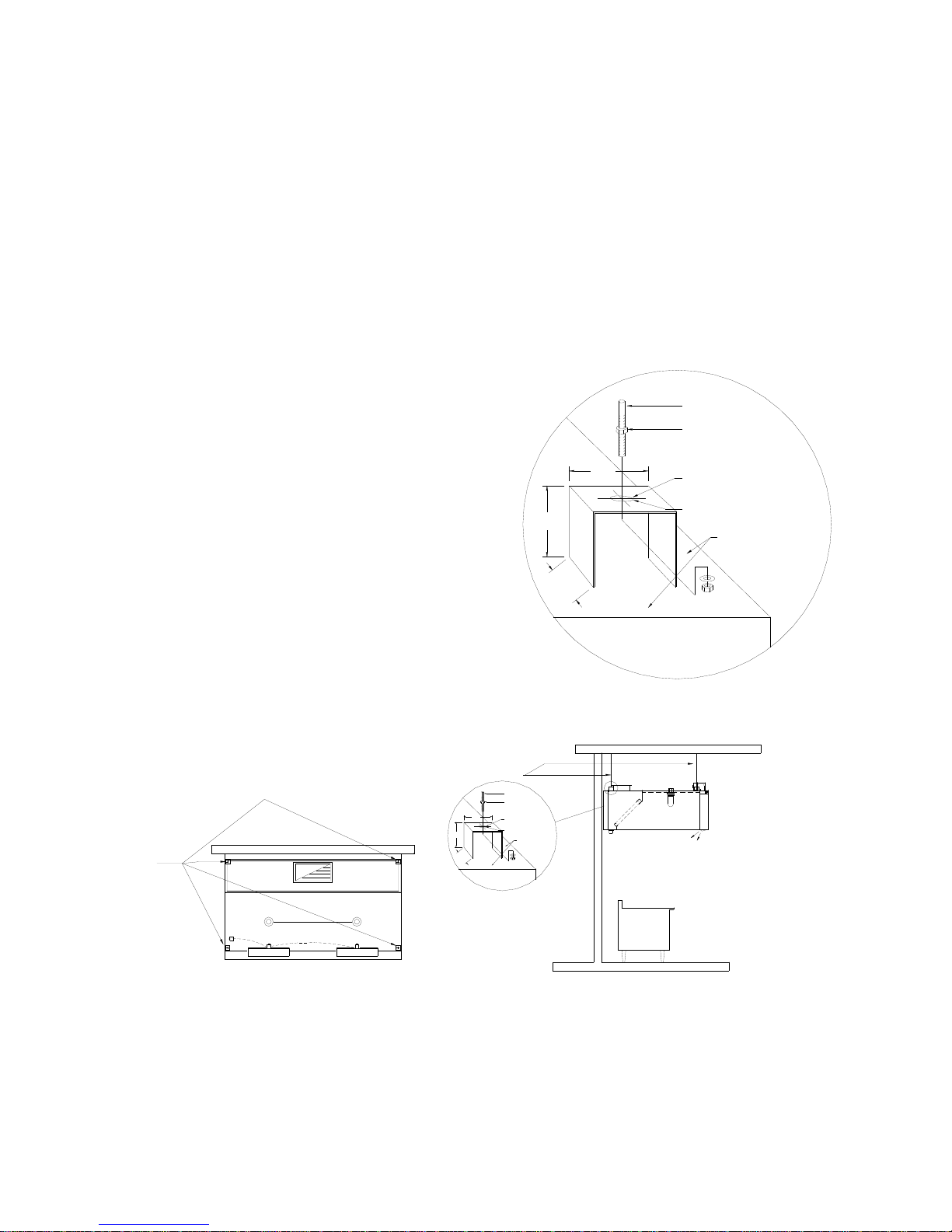
Dynaflow Installation
The Dynaflow hoods are hung from 4 or more hanging brackets
(depending on the model) mounted on top of the hoods as
indicated on the engineering drawings. The engineering
drawings indicate number and location of the hanger bracket.
All hanger brackets shown on the Spring Air Systems
drawings must be used to support the hood. Spring Air
Systems assumes no responsibility for the field installation
of the any hood.
A typical schematic is shown to the right with recommend
method on installing the hanger rods to the hanger brackets.
The size of the hanger rods, washers and nuts must be
determined by a structural engineer based on hood weight and
site conditions. All hood weight is shown on the Spring Air
Systems section view drawing. The hanger rods must be size to
safely hold the weight of the hood from the structure above.
The structure above must be designed to hold the weight of the
hood. Structural engineers will be required to determine what is
acceptable. The hanger bracket diagram indicates how the rod
is attached to the hood. All hanger rods must be installed
perpendicular to the roof of the hood.
2.25"
2.5
TOP OF
2.5"
HOOD
TYPICAL HANGER ROD
BRACKET ISOMETRIC
(FROM FRONT OF HOOD)
Hanger Rod Schematic
HANGER ROD
HANGER ROD NUT
PRE DRILLED HOLE,
ACCEPTS UP TO
1/2" Ø ROD
Ø 17/32"
HANGER BRACKET
OFFSET 1/2" FROM
EDGE OF HOOD
ure 6
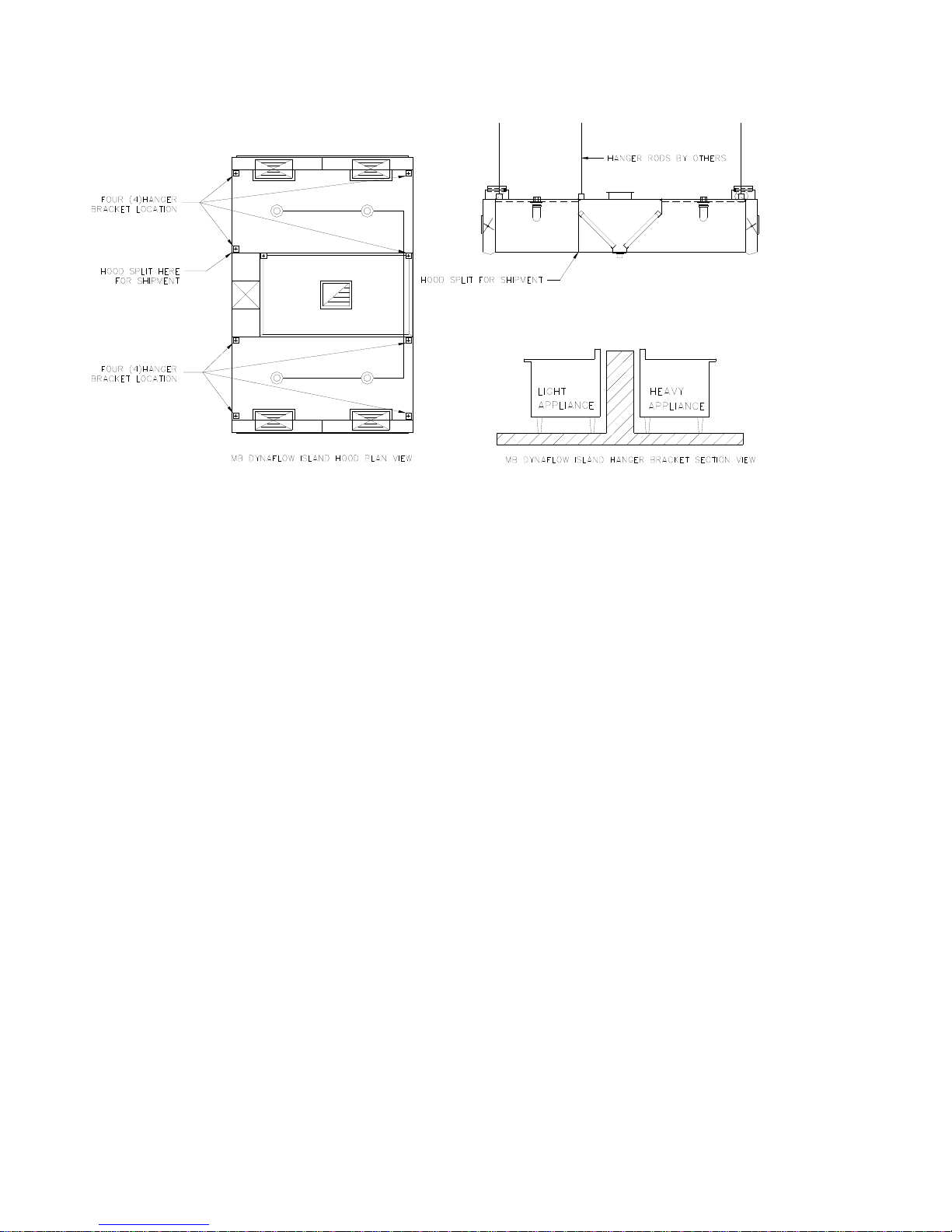
FOUR (4)HANGER
BRACKET LOCATION
MJ DYNAFLOW PLAN VIEW
Wall mounted Dynaflow model FN-B-MJ Hood in Plan and Section View showing hanger rod locations.
HANGER ROD BY INSTALLER
HANGER ROD
HANGER ROD NUT
PRE DRILLED HOLE,
2.5
ACCEPTS UP TO
1/2" Ø ROD
2.25"
2.5"
MJ BLOWERMJ BLOWER
Ø17/32"
TOP OF
HOOD
TYPICAL HANGER ROD
BRACKET ISOMETRIC
(FROM FRONT OF HOOD)
HANGER BRACKET
OFFSET 1/2" FROM
EDGE OF HOOD
MJ DYNAFLOW HANGER BRACKET SECTION VIEW
APPLIANCE
ure
5
Fig
Typical Island Dynaflow model FN-DB-MB in Plan and Section View showing hanger rod locations.
ure 8
Your Dynaflow hood must be installed in accordance with the building permit issued for the commercial kitchen. The
hood may be mounted against a wall or in an island configuration.
The Dynaflow hood must be installed in accordance with the current edition of the NFPA-96, all local building codes, all
state or provincial building codes, all national building codes, and the authority having jurisdiction.
A commercial kitchen exhaust fan must be installed on the roof or wall mounted and connected to the hood by liquid tight
all welded duct in accordance to the current edition of the NFPA-96. A dedicated fresh air unit may also be installed
depending on the local code requirements for your area. Place the hood on the ground in the position it will hang below
the hanger rods. The hood must rest on wood 2”x 4” or some other soft material to prevent damages to the bottom edges.
When lifting the hood, support from the underside at the four corners. Otherwise the hood ends or sides may buckle. Lift
the hood straight up. Do not remove the lifting device until the hood is secure. After the hood is securely hung the exhaust
and supply ductwork can be connected.
Welding the Exhaust Duct to the Hood Exhaust Duct Collar
A “FD” Dynaflow hood is supplied with an Exhaust duct collar fire damper in the hood exhaust duct collar. The fire
damper must be closed before welding the hood duct collar to the exhaust duct. We recommend the exhaust duct be
continuously welded to the exhaust duct collar of the hood per the current edition of the NFPA-96. The fire damper is
closed by removing the link/cable assembly from the hook on the inside of the hood exhaust duct collar. Check to ensure
the damper moves freely open and closed within the exhaust duct collar after installation of the exhaust duct. Once the
welding is complete the link/cable assembly mu st be connected to the hook to open the fire damper. See the next section
for details on the cable/link assembly.
Supply ductwork, electrical wiring and plumbing must be installed in accordance with all applicable municipal, state,
provincial and national codes.
6
Fig
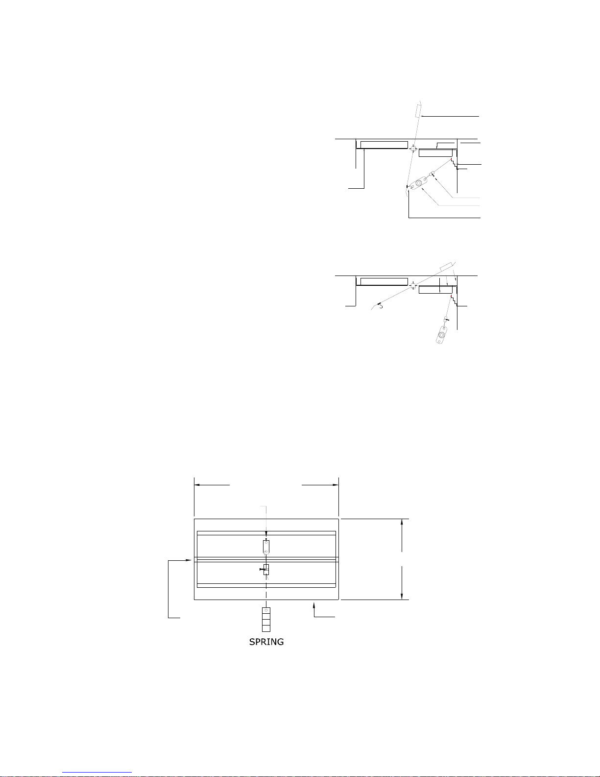
ARRANGEMENT “D” FIRE DAMPER ASSEMBLIES:
Provide on all FD Dynaflow Hoods.
(FN Hoods do not have a fire damper in the exhaust
duct collar)
Description:
The section view of the exhaust fire damper to the right
shows a cross section of the exhaust duct collar, fire
damper blade, fusible link, adjustable cable block, spring,
and stainless steel cable when the damper is in the set
position.
In the event of a fire in the exhaust duct collar, th e fusible
link melts, releasing the fire damper, which closes tight
on the damper blade stops and seals. The second drawing
shows the damper as the fusible link has been removed.
The damper will rotate clockwise against the damper bar
weight and close.
The complete assembly is part of the UL/ULC listed
Spring Air Systems “Commercial Kitchen Exhaust Hood
with Fire Damper”.
DAMPER BLADE
STOPS
SECTION VIEW OF ASSEMBLE FUSIBLE LINK
SECTION VIEW OF DISASSEMBLE FUSIBLE LINK
Link/Cable Assembly
ure 9
Link/Cable Assemblies for various Exhaust Duct Collar Sizes.
Dampers up to 18” long:
UP TO 18"
DAMPER BLADE
DUCT FLANGE
DAMPER BLADE STOPS
SPRING
CABLE BLOCK
FUSIBLE LINK
PIN
FIRE DAMPER
SHAFT
Exhaust Fire Damper up to 18” long
FIRE DAMPER
BLADE
Figure 10
PIN
WIDTH
EXHAUST DUCT
COLLAR PERIMETER
7
 Loading...