

SprayTECH CAPspray AirCoat 0508074 Owner's Manual
EnglishFrançaisEspañol
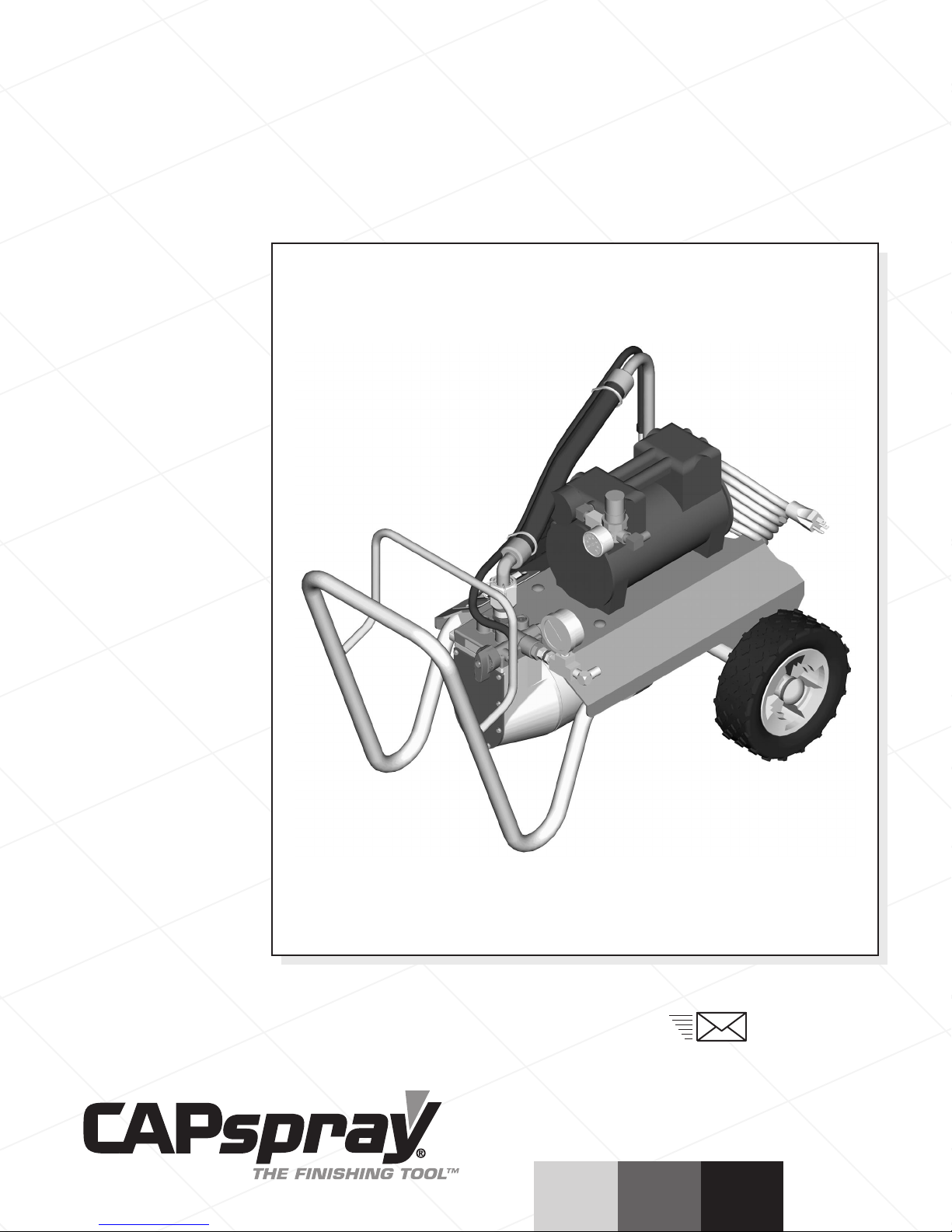
AirCoat Spray System
Owner’s Manual • Manuel de l'utilisateur • Manual del propietario
1203 © 2003 SprayTECH. All rights reserved. Form No. 0551366A
CAPSpray
1770 Fernbrook Lane
Minneapolis, MN 55447
Technical Assistance: 1-800-292-4637
Order Entry: 1-800-443-4500
Fax: 1-800-525-9501
www.spraytechinc.com
Model Number 0508074
English
2©SprayTECH. All rights reserved.
Table of Contents
Safety Precautions . . . . . . . . . . . . . . . . . . . . . . . . . . . . . . . 2
Grounding Instructions. . . . . . . . . . . . . . . . . . . . . . . . . . . . 3
General Description . . . . . . . . . . . . . . . . . . . . . . . . . . . . . . 3
Setup . . . . . . . . . . . . . . . . . . . . . . . . . . . . . . . . . . . . . . . . . . 4
Operation . . . . . . . . . . . . . . . . . . . . . . . . . . . . . . . . . . . . . . 4
Priming the Pump . . . . . . . . . . . . . . . . . . . . . . . . . . . . . . . 4
Painting. . . . . . . . . . . . . . . . . . . . . . . . . . . . . . . . . . . . . . . 5
Pressure Relief Procedure. . . . . . . . . . . . . . . . . . . . . . . . . 6
Spraying Technique . . . . . . . . . . . . . . . . . . . . . . . . . . . . . . 6
Cleanup . . . . . . . . . . . . . . . . . . . . . . . . . . . . . . . . . . . . . . . . 7
Overnight Storage . . . . . . . . . . . . . . . . . . . . . . . . . . . . . . . 7
Long Term Storage . . . . . . . . . . . . . . . . . . . . . . . . . . . . . . 7
Maintenance . . . . . . . . . . . . . . . . . . . . . . . . . . . . . . . . . . . . 8
Removing and Cleaning the Inlet Valve . . . . . . . . . . . . . . . 8
Removing and Cleaning the Outlet Valve. . . . . . . . . . . . . . 8
Troubleshooting . . . . . . . . . . . . . . . . . . . . . . . . . . . . . . . . . 9
Parts List. . . . . . . . . . . . . . . . . . . . . . . . . . . . . . . . . . . . . . 28
Warranty . . . . . . . . . . . . . . . . . . . . . . . . . . . . . . . . . . . . . . 36
Safety Precautions
This manual contains information that must be read and
understood before using the equipment. When you come to an
area that has one of the following symbols, pay particular
attention and make certain to heed the safeguard.
This symbol indicates a potential hazard that may cause
serious injury or loss of life. Important safety information will
follow.
This symbol indicates a potential hazard to you or to the
equipment. Important information that tells how to prevent
damage to the equipment or how to avoid causes of minor
injuries will follow.
The diaphragm pump is provided with a thermally
protected automatic reset. If an overload occurs the
thermally protected automatic reset disconnects the motor
from the power supply.
• The motor will restart without warning when the protector
automatically resets.
• Always disconnect the motor from the power supply
before working on the equipment.
• When the thermally protected automatic reset disconnects
the motor from the power supply, relieve pressure by
turning the PRIME/SPRAY valve to PRIME.
•Turn the pump ON/OFF switch to OFF.
NOTE: The cause of the overload should be corrected
before restarting. Refer to the Troubleshooting
section.
CAUTION
NOTE: Notes give important information which should
be given special attention.
CAUTION
WARNING
HAZARD: Injection injury - A high pressure fluid stream
produced by this equipment can pierce the skin
and underlying tissues, leading to serious
injury and possible amputation. See a
physician immediately.
DO NOT TREAT AN INJECTION INJURY AS A SIMPLE CUT!
Injection can lead to amputation. See a physician
immediately.
The maximum operating range of the unit is 2800 PSI / 19
MPa fluid pressure.
PREVENTION:
• NEVER aim the gun at any part of the body.
• NEVER allow any part of the body to touch the fluid stream.
DO NOT allow body to touch a leak in the fluid hose.
• NEVER put hand in front of the gun. Gloves will not
provide protection against an injection injury.
•ALWAYS lock gun trigger, shut pump off, and release all
pressure before servicing, cleaning tip or guard, changing
tip, or leaving unattended. Pressure will not be released
by turning off the motor. The PRIME/SPRAY valve handle
must be turned to PRIME to relieve the pressure. Refer to
the PRESSURE RELIEF PRESSURE described in the
pump manual.
•ALWAYS keep tip guard in place while spraying. The tip
guard provides some protection but is mainly a warning
device.
•ALWAYS remove the spray tip before flushing or cleaning
the system.
• Paint hose can develop leaks from wear, kinking and
abuse. A leak can inject material into the skin. Inspect
the hose before each use.
• NEVER use a spray gun without a working trigger lock
and trigger guard in place.
• All accessories must be rated at or above 2800 PSI / 19
MPa. This includes spray tips, guns, extensions, and hose.
HAZARD: EXPLOSION AND FIRE - Solvent and paint
fumes can explode or ignite. Severe injury
and/or property damage can occur.
PREVENTION:
• Provide extensive exhaust and fresh air introduction to
keep the air within the spray area free from accumulation
of flammable vapors.
•Avoid all ignition sources such as static electricity sparks,
electrical appliances, flames, pilot lights, hot objects, and
sparks from connecting and disconnecting power cords or
working light switches.
•Do not smoke in spray area.
• Fire extinguisher must be present and in good working
order.
• Place pump at least 20 feet (6.1 m) from the spray object
in a well ventilated area (add more hose if necessary).
Flammable vapors are often heavier than air. Floor area
must be extremely well ventilated. The pump contains
arcing parts that emit sparks and can ignite vapors.
• The equipment and objects in and around the spray area
must be properly grounded to prevent static sparks.
• Use only conductive or grounded high-pressure fluid hose.
Gun must be grounded through hose connections.
• Power cord must be connected to a grounded circuit.
NOTE TO PHYSICIAN:
Injection into the skin is a traumatic injury. It is
important to treat the injury as soon as possible. DO
NOT delay treatment to research toxicity. Toxicity is a
concern with some coatings injected directly into the
blood stream. Consultation with a plastic surgeon or
reconstructive hand surgeon may be advisable.
WARNING
• Always flush unit into separate metal container, at low
pump pressure, with spray tip removed. Hold gun firmly
against side of container to ground container and prevent
static sparks.
• Follow material and solvent manufacturer's warnings and
instructions.
• Use extreme caution when using materials with a
flashpoint below 70° F (21° C). Flashpoint is the
temperature at which a fluid can produce enough vapors
to ignite.
• Plastic can cause static sparks. Never hang plastic to
enclose spray area. Do not use plastic drop cloths when
spraying flammable materials.
• Use lowest possible pressure to flush equipment.
GAS ENGINE (WHERE APPLICABLE)
Always place unit outside of structure in fresh air. Keep all
solvents away from engine exhaust. Never fill fuel tank with a
running or hot engine. Hot surface can ignite spilled fuel.
Always attach ground wire from pump to a grounded object.
Refer to engine owner’s manual for complete safety
information.
HAZARD: EXPLOSION HAZARD DUE TO INCOMPATIBLE
MATERIALS - will cause severe injury or
property damage.
PREVENTION:
• Do not use materials containing bleach or chlorine.
• Do not use halogenated hydrocarbon solvents such as
bleach, mildewcide, methylene chloride and 1,1,1 trichloroethane. They are not compatible with aluminum.
• Contact your coating supplier about the compatibility of
material with aluminum.
HAZARD: HAZARDOUS VAPORS - Paints, solvents,
insecticides, and other materials can be
harmful if inhaled or come in contact with body.
Vapors can cause severe nausea, fainting, or
poisoning.
PREVENTION:
• Use a respirator or mask if vapors can be inhaled. Read
all instructions supplied with the mask to be sure it will
provide the necessary protection.
•Wear protective eyewear.
•Wear protective clothing as required by coating
manufacturer.
HAZARD: GENERAL - Can cause severe injury or
property damage.
PREVENTION:
• Read all instructions and safety precautions before
operating equipment.
• Follow all appropriate local, state, and national codes
governing ventilation, fire prevention, and operation.
• The United States Government Safety Standards have
been adopted under the Occupational Safety and Health
Act (OSHA). These standards, particularly part 1910 of
the General Standards and part 1926 of the Construction
Standards, should be consulted.
• Use only manufacturer authorized parts. User assumes
all risks and liabilities when using parts that do not meet
the minimum specifications and safety devices of the
pump manufacturer.
• Before each use, check all hoses for cuts, leaks, abrasion
or bulging of cover. Check for damage or movement of
couplings. Immediately replace hose if any of those
conditions exist. Never repair a paint hose. Replace with
a grounded high-pressure hose.
• All hoses, swivels, guns, and accessories must be
pressure rated at or above 2800 PSI / 19 MPa.
• Do not spray outdoors on windy days.
•Wear clothing to keep paint off skin and hair.
• Always unplug cord from outlet before working on
equipment.
Grounding Instructions
This product must be grounded. In the event of an electrical
short circuit, grounding reduces the risk of electric shock by
providing an escape wire for the electric current. This product
is equipped with a cord having a grounding wire with an
appropriate grounding plug. The plug must be plugged into an
outlet that is properly installed and grounded in accordance
with all local codes and ordinances.
DANGER — Improper installation of the grounding plug can
result in a risk of electric shock. If repair or replacement of the
cord or plug is necessary, do not connect the green grounding
wire to either flat blade terminal. The wire with insulation
having a green outer surface with or without yellow stripes is
the grounding wire and must be connected to the grounding
pin.
Check with a qualified electrician or serviceman if the
grounding instructions are not completely understood, or if you
are in doubt as to whether the product is properly grounded.
Do not modify the plug provided. If the plug will not fit the
outlet, have the proper outlet installed by a qualified
electrician.
Use only a 3-wire extension cord that has a 3-blade
grounding plug and a 3-slot receptacle that will accept the
plug on the product. Make sure your extension cord is in
good condition. When using an extension cord, be sure
to use one heavy enough to carry the current your
product will draw. An undersized cord will cause a drop
in line voltage resulting in loss of power and overheating.
A 12 gauge cord is recommended. If an extension cord is
to be used outdoors, it must be marked with the suffix WA after the cord type designation. For example, a
designation of SJTW-A would indicate that the cord would
be appropriate for outdoor use.
CAUTION
© SprayTECH. All rights reserved. 3
English
Grounded Outlet
Grounding Pin
Cover for grounded outlet box
General Description
This fine finish spray system is versatile enough to use for low
pressure fine finish work as well as high pressure airless
spraying. The system includes a diaphragm paint pump and
an air compressor that work together to provide this versatility.
Setup
Use this procedure to set up the spray system.
1. Make sure the pump ON/OFF switch and the compressor
ON/OFF switch are in the OFF position.
2. Make sure the pressure control knob is turned fully
counterclockwise to its lowest pressure setting.
3. Lock the gun by turning the gun lock nut clockwise (when
looking from the back of the gun) until it stops. This
closes the material valve in the gun.
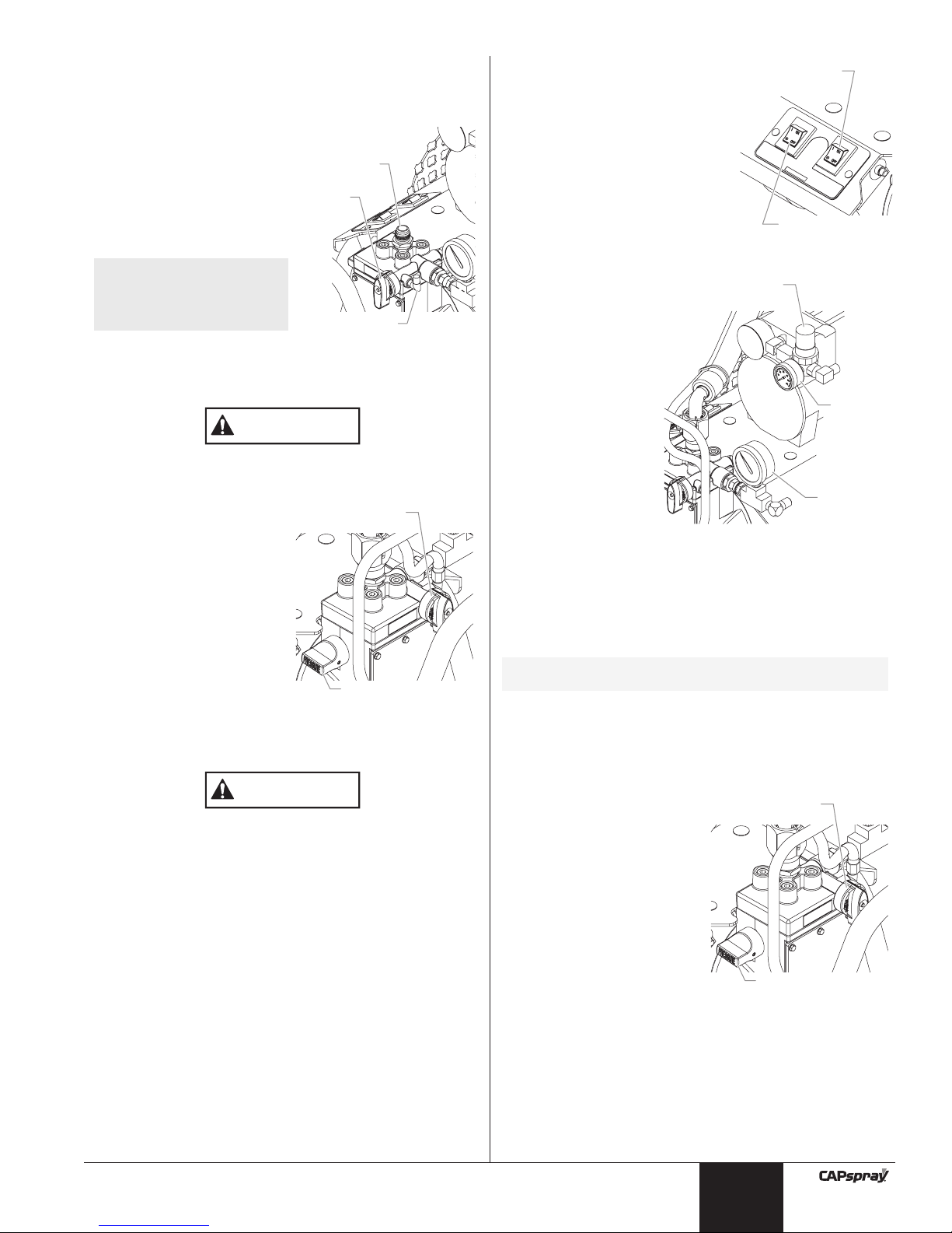
4. Using a wrench, attach a
minimum of 50’ of 1/4” nylon
airless spray hose to the
material outlet fitting on the
pump. Tighten securely.
5. Attach the spray hose to the
material inlet fitting on the spray
gun. Using two wrenches (one
on the gun and one on the
hose), tighten securely.
Make sure all airless hoses and
spray guns are electrically
grounded and rated for at least
2800 PSI (19 MPa) fluid pressure.
WARNING
4©SprayTECH. All rights reserved.
6. Attach the air hose to the air outlet fitting on the
compressor. Tighten securely.
7. Attach the air hose to the air inlet fitting on the spray gun.
Tighten securely.
Reversing the hose connections could result in serious
injury. Make sure the airless spray hose is connected
from the diaphragm pump to the material inlet fitting on
the gun and the air hose is connected from the
compressor to the air inlet fitting on the gun.
8. Make sure the electrical service is 120V, 15 amp minimum.
9. Plug the power cord into a properly grounded outlet at
least 25’ from the spray area.
Always use a minimum 12 gauge, three-wire extension
cord with a grounded plug. Never remove the third prong
or use an adapter.
10. Firmly press the pusher valve button on the side of the pump
housing to make sure the outlet ball valve moves freely.
Operation
Use the following procedures to operate the spray system.
Priming the Pump
Preparing to Prime
1. Fill the inlet valve with water or
with a light household oil.
2. Make sure that the
PRIME/SPRAY valve is set to
PRIME and that the pressure
control knob is turned
counterclockwise to its lowest
pressure setting.
3. Turn on the pump by moving the
pump ON/OFF switch to the ON
position.
4. Increase the pressure by turning
the pressure control knob
clockwise 1/2 turn.
5. Force the inlet valve to open and
close by pushing on it with a
screwdriver or the eraser end of
a pencil. It should move up and
down about 1/16 of an inch.
Continue until water or oil is
sucked into the pump. This will
wet the moving parts and break
loose any old paint residue.
6. Put the palm of your hand over
the inlet. Turn the pressure
control knob clockwise to its
maximum setting. You should
feel suction coming from the inlet
valve. If you do not, refer to the “Removing and Cleaning
the Outlet Valve” procedure in the Maintenance section.
PRIME/SPRAY
Val ve
CAUTION
WARNING
English
Air Pressure
Regulator
Air Compressor
Air
Outlet
Fitting
Air
Pressure
Gauge
Material
Outlet Fitting
Material Pressure
PRIME/SPRAY
Pressure
Control
Knob
Val ve
Return Hose
Suction Hose
Gauge
Diaphragm Pump
Pump ON/OFF
Switch
Pusher Valve Button
Compressor
ON/OFF
Switch
Pressure Control Knob
Gun Lock Nut
Air Inlet
Fitting
Material
Inlet
Fitting
7. Turn the pressure control knob counterclockwise to the
minimum pressure setting.
8. Turn the pump ON/OFF switch to OFF.
Priming
1. Attach the suction set to the
pump.
a. Thread the suction hose
nut onto the inlet valve on
the pump.
b. Thread the return hose
onto the return hose fitting
on the pump.
2. Place the suction set into a
container of paint.
3. Turn the pressure control knob counterclockwise to the
minimum pressure setting.
Always reduce the pressure to zero before changing the
position of the PRIME/SPRAY valve. Failure to do so may
cause damage to the paint pump diaphragm.
4. Turn the PRIME/SPRAY
valve to PRIME.
5. Move the pump ON/OFF
switch to the ON position.
6. Turn the pressure control
knob clockwise to between
half and full pressure. Let
the unit prime 1 to 2
minutes after paint begins
to flow through the return
hose until no bubbles are
present.
7. Turn the pressure control
knob counterclockwise to
the minimum pressure
setting.
8. Move the pump ON/OFF switch to the OFF position.
If the pressure control knob is reduced to zero and the
PRIME/SPRAY valve is still on SPRAY while the pump is
operating, there will be high pressure in the hose and
spray gun until the PRIME/SPRAY valve is turned to
PRIME or until the spray gun is triggered to relieve the
pressure.
Painting
The AirCoat spray system has two different painting modes.
The AirCoat mode is used for fine finish work with low to
medium viscosity materials (oil, stains, lacquers, etc...). The
airless mode is used for general painting with high viscosity
materials (latex).
Painting in AirCoat Mode
Use the AirCoat mode for low-pressure fine finish work (pump
pressure up to 1000 PSI).
1. Make sure that the airless spray hose is free of kinks and
clear of objects with sharp cutting edges.
2. Turn the pressure control knob counterclockwise to its
lowest setting.
3. Turn the compressor air pressure regulator
counterclockwise to its lowest setting.
CAUTION
CAUTION
NOTE: The pump can be
used with the
optional hopper
accessory instead
of the suction set.
Inlet
Val ve
PRIME/
SPRAY
Val ve
Return
Hose Fitting
4. Move the compressor ON/OFF
switch to the ON position.
5. Move the pump ON/OFF switch
to the ON position.
6. Turn the PRIME/SPRAY valve to
SPRAY.
7. Turn the pressure control knob
clockwise until the material
pressure gauge reads 400 PSI.
The paint hose should stiffen as
paint begins to flow through it.
8. Turn the air pressure regulator
clockwise until the air pressure
gauge reads 20 PSI.
9. Unlock the gun by
turning the gun lock
nut counterclockwise (when
looking from the
back of the gun)
three full turns. This
opens the material
valve in the gun.
10. Trigger the spray gun
to bleed air out of the
material hose.
11. When material
reaches the spray
tip, spray a test area
to check the spray
pattern.
12. Adjust the spray
pattern to the desired size and atomization.
a. Use the pressure control knob to control the flow of
paint to the gun.
b. Use the air pressure regulator to control the amount of
atomization air available to the gun.
c. Use the pattern adjustment knob on the gun to fine
tune the spray pattern.
Painting in Airless Mode
Use the airless mode for general high-pressure spraying
(pump pressure from 500 to 2000 PSI).
1. Make sure that the airless spray hose is free of kinks and
clear of objects with sharp cutting edges.
2. Turn the pressure control
knob counterclockwise to its
lowest setting.
3. Turn the PRIME/SPRAY
valve to SPRAY.
4. Move the pump ON/OFF
switch to the ON position.
5. Turn the pressure control
knob clockwise to its
highest setting. The paint
hose should stiffen as paint
begins to flow through it.
6. Unlock the gun by turning
the gun lock nut counterclockwise (when looking from the back of the gun) three
full turns. This opens the material valve in the gun.
7. Trigger the spray gun to bleed air out of the material hose.
8. When material reaches the spray tip, spray a test area to
check the spray pattern.
PRIME/SPRAY
Val ve
Pressure
Control Knob
NOTE: Refer to the spray gun Owner’s Manual for
information on the operation of the gun.
Air
Pressure
Gauge
Material
Pressure
Gauge
Compressor
ON/OFF Switch
Pump ON/OFF
Switch
© SprayTECH. All rights reserved. 5
English
PRIME/SPRAY
Val ve
Pressure
Control Knob
Air Pressure
Regulator
Air
Air
Pressure
Pressure
Gauge
Gauge
Material
Material
Pressure
Pressure
Gauge
Gauge
9. Use the lowest pressure setting necessary to get a good
spray pattern. If the pressure is set too high, the spray
pattern will be too light. If the pressure is set too low,
tailing will appear or the paint will spatter out in “gobs”
rather than in a fine spray.
Pressure Relief Procedure
Follow this procedure after the unit is assembled and before
any operation that involves the spray gun such as cleaning
and maintenance or changing tips or accessories.
1. Turn the pressure control
knob counterclockwise to its
lowest setting.
2. Turn the PRIME/SPRAY
valve to the PRIME
position.
3. Trigger the gun to remove
any pressure that still may
be in the hose.
4. Lock the gun by turning the
gun lock nut clockwise
(when looking from the back
of the gun) until it stops.
This closes the material
valve in the gun.
Injection hazard. Do not spray without the tip guard in
place. NEVER trigger the gun unless the tip is completely
turned to either the spray or the unclog position. ALWAYS
engage the gun trigger lock before removing, replacing or
cleaning tip.
WARNING
PRIME/SPRAY
Val ve
Pressure
Control Knob
Good spray pattern
Paint tailing pattern
6©SprayTECH. All rights reserved.
Spraying Technique
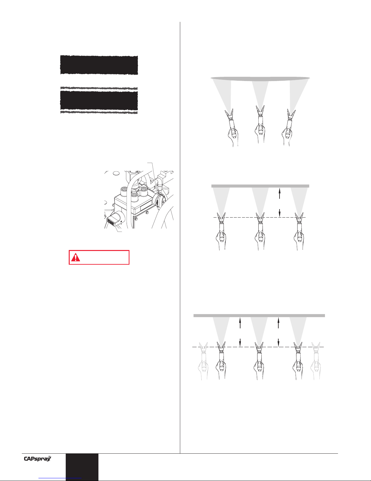
The key to a good paint job is an even coating over the entire
surface. This is done by using even strokes. Keep your arm
moving at a constant speed and keep the spray gun at a
constant distance from the surface. The best spraying
distance is 10 to 12 inches between the spray tip and the
surface.
Keep the spray gun at right angles to the surface. This means
moving your entire arm back and forth rather than just flexing
your wrist.
Keep the spray gun perpendicular to the surface, otherwise
one end of the pattern will be thicker than the other.
The spray gun should be triggered by turning it on and off with
each stroke. This will save paint and avoid paint buildup at the
end of the stroke. Do not trigger the gun during the middle of
a stroke. This will result in an uneven spray and splotchy
coverage.
Overlap each stroke by about 30%. This will ensure an even
coating.
When you stop painting, lock the gun trigger lock, turn the
pressure control knob counterclockwise to its lowest setting
and set the priming knob to PRIME. Turn the motor switch to
OFF and unplug the sprayer.
If you expect to be gone more than 1 hour, follow the short
term clean up procedure described in the Cleanup section of
this manual.
Keep stroke smooth and at an even speed.
Even coat throughout
Approximately
10 to 12 inches
Heavy Coat
Do not flex wrist while spraying.
Light Coat Light Coat
English
Proper way to trigger the spray gun
Keep stroke
even
Start stroke End strokePull trigger Release triggerKeep steady
Aproximately
10 to 12 inches

Cleanup
Overnight Storage
Shutdown
1. Turn the pressure control
knob counterclockwise to
the minimum setting.
2. Turn the PRIME/SPRAY
valve to PRIME.
3. Move the pump ON/OFF
switch to the OFF position.
4. Move the compressor
ON/OFF switch to the OFF
position.
5. Wait a couple seconds, then
trigger the gun into the
material container to
release built up fluid
pressure from the pump and air pressure from the
compressor.
6. Lock the gun by turning the gun lock nut clockwise (when
looking from the back of the gun) until it stops. This
closes the material valve in the gun.
7. Unplug the unit.
8. For latex materials only, pour 1/2 cup water slowly on the
top of the paint to prevent the paint from drying. For other
materials, seal the material container keeping the return
hose in the paint.
9. Wrap the spray gun assembly in a damp cloth and place it
in a plastic bag. Seal the bag shut.
10. Place the unit in a safe place out of the sun for short-term
storage.
Startup
1. Remove the gun from the plastic bag.
2. Stir the water into the paint for latex materials. Remove
the cover from the material container and stir the paint for
all other materials.
3. Perform the appropriate procedure in the “Painting”
section of this manual for the type of spraying that will be
performed.
Long-Term Storage
Do not allow paint to build up on the motor or the motor
will overheat. Do not allow flammable solvents to come in
contact with the motor or they could ignite.
Do not use mineral spirits or paint thinner on latex paint,
or the mixture will turn into a jelly-like substance which is
difficult to remove.
CAUTION
NOTE: If spraying with latex paint, use warm soapy
water for cleaning. If using oil or alkyd-based
paints, use mineral spirits or paint thinner.
WARNING
PRIME/SPRAY
Val ve
Pressure
Control Knob
Clearing the Suction Tube
1. Turn the pressure control knob
counterclockwise to the minimum
setting.
2. Turn the PRIME/SPRAY valve to
PRIME.
3. Move the pump ON/OFF switch
to the OFF position.
4. Move the compressor ON/OFF
switch to the OFF position.
5. Wait a couple seconds, then
trigger the gun into the material
container to release built up fluid
pressure from the pump and air
pressure from the compressor.
6. Lock the gun by turning the gun lock nut clockwise (when
looking from the back of the gun) until it stops. This
closes the material valve in the gun.
7. Remove the suction hose from the material and hold it
above a bucket of water or solvent. Leave the return hose
in the material bucket.
Do not use mineral spirits or paint thinner on latex paint,
the mixture will turn into a jelly-like substance that is
difficult to remove.
8. Move the pump ON/OFF switch to the ON position.
9. Turn the pressure control knob to 1/2 maximum pressure.
This will draw the remaining material in the suction hose
through the pump, down the return hose and into the
material bucket.
10. Turn the pressure control knob counterclockwise to the
minimum setting.
11. Remove the spray tip and guard and place them into a
container of the appropriate solvent.
12. Place the attached suction hose and return hose into the
container of water or appropriate solvent.
13. Increase the pressure to 1/2 the maximum pressure. Let
the water or solvent circulate for 2-3 minutes to flush paint
out of the pump, the suction hose and the return hose.
Clearing the Paint Hose
1. Turn the pressure control knob counterclockwise to the
minimum pressure setting.
2. Turn the PRIME/SPRAY
valve to SPRAY.
3. Unlock the gun by turning
the gun lock nut counterclockwise (when looking
from the back of the gun)
three full turns. This opens
the material valve in the gun.
4. Carefully trigger the gun
with the spray tip removed
against the inside of the
material container.
5. Turn the pressure control
knob slowly clockwise until
material starts to flow into the container. As soon as the
water or solvent starts to come into the container, release
the trigger.
6. Change to clean water or solvent and continue circulating
for another 5 minutes to thoroughly clean the hose, pump
and spray gun.
7. Turn the pressure control knob counterclockwise to its
lowest setting.
8. Turn the PRIME/SPRAY valve to PRIME.
9. Trigger the gun into the water or solvent container to
release built up fluid pressure from the pump.
PRIME/SPRAY
Val ve
Pressure
Control Knob
CAUTION
Compressor
ON/OFF Switch
Pump ON/OFF
Switch
© SprayTECH. All rights reserved. 7
English
10. Lock the gun by turning the gun lock nut clockwise (when
looking from the back of the gun) until it stops. This
closes the material valve in the gun.
11. Move the pump ON/OFF switch to the OFF position.
Final Cleanup
1. Remove the suction set from the inlet valve.
2. Clean the threads of the inlet valve with a damp cloth.
3. Fill the inlet valve with water or
with a light household oil.
4. Make sure that the
PRIME/SPRAY valve is set to
PRIME and that the pressure
control knob is turned
counterclockwise to its lowest
pressure setting.
5. Turn on the pump by moving the
pump ON/OFF switch to the ON
position.
6. Increase the pressure by turning
the pressure control knob
clockwise 1/2 turn.
7. Turn the PRIME/SPRAY valve to
SPRAY to distribute the oil.
8. Turn the pressure control knob counterclockwise to its
lowest setting.
9. Turn the PRIME/SPRAY valve to PRIME.
10. Unlock and trigger the gun to remove any pressure that
may still be in the hose.
11. Lock the gun by turning the gun lock nut clockwise (when
looking from the back of the gun) until it stops. This
closes the material valve in the gun.
12. Turn off the pump by moving the pump ON/OFF switch to
the OFF position
13. Remove the material hose and air hose from the spray
gun using two adjustable wrenches. Refer to the spray
gun Owner’s Manual for gun cleaning instructions.
14. Wipe the entire unit, hose, and gun with a damp cloth to
remove accumulated paint.
Maintenance
Follow these procedures when encountering problems
indicated in the troubleshooting section.
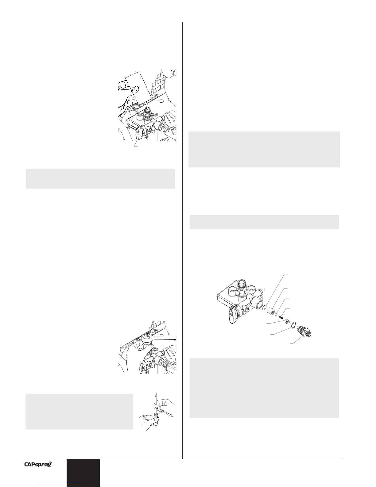
Removing and Cleaning the Inlet Valve
1. Perform the Pressure Relief
Procedure, turn off and unplug
the unit.
2. Remove the inlet valve assembly
using a 27 millimeter socket or
box end wrench.
3. Test movement of the valve by
pushing on it from the open end
of the valve housing with a
screwdriver or the eraser end of
a pencil. It should move about 1/16 of an inch. If it does
not move, it should be cleaned or replaced.
NOTE: The inlet valve must be oiled
after every job. This will
reduce or eliminate priming
problems the next time the
unit is used as well as extend
the life of the valve.
NOTE: Proper cleaning and oiling of the pump after
use are the most important steps to perform
to insure proper operation after storage.
PRIME/SPRAY
Val ve
8©SprayTECH. All rights reserved.
4. Thoroughly clean the valve assembly with water or the
appropriate solvent. Use a small brush.
5. If the valve has been properly cleaned and water drips out
of the bottom, the valve is worn and needs to be replaced.
A properly seated valve filled with water and held vertically
will not drip.
6. Install a new or cleaned valve in the pump block and then
fill the valve with light oil or solvent.
Removing and Cleaning the Outlet
Valve
It may be necessary to remove and clean the outlet valve or to
replace parts inside the valve worn out through normal use.
1. Remove the outlet valve body with a wrench.
2. Remove and clean the ball stop and small spring inside
the valve using a wire hook or tweezers. Replace the
spring if it is broken or worn.
3. Remove the seat and ball assembly.
4. Clean all parts thoroughly. If the ball or seat show any
sign of wear or damage, replace them with new parts.
This carbide ball must seal tightly against its seat for the
valve to function properly.
5. Cover all parts with a thin coat of light oil before
reassembling.
6. Drop in the valve ball.
7. Insert the protector and spring and replace the valve body.
Be sure that the O-ring is positioned properly and that the
tongue on the cap fits inside the spring.
8. Tighten the valve body securely with an adjustable
wrench. Do not over-tighten.
NOTE: Wear on the ball is almost impossible to
detect visually. To test for a worn outlet valve
assembly, turn the pressure control knob
clockwise to its highest setting and run water
only through the pump for 10 to 15 minutes
without triggering the gun.
If the valve is defective, the end cap will get
very hot to the touch. If it is functioning
properly, it will stay approximately the same
temperature as the water running through it.
NOTE: Align the ridge on the seat with the groove in
the pump housing when reassembling.
NOTE: This spring is manufactured to a very specific
tension. Do not stretch the spring. Do not put in
an unauthorized substitute. See the paint pump
assembly parts diagram for the proper
replacement part number. An extra spring is
included in the literature set.
English
Seal
Seat
Ball
Spring
Ball Stop
O-ring
Valve Body

English
© SprayTECH. All rights reserved. 9
Troubleshooting
Solution
1. Plug the unit in.
2. Turn the ON/OFF switch to ON.
3. Replace the blown fuse with the proper
replacement.
4. Properly test the power supply voltage.
5. Turn the PRIME/SPRAY knob to PRIME.
6. Replace the extension cord.
7. Allow the motor to cool and move the unit to a
cooler spot.
8. Take the unit to a SprayTECH Authorized Service
Center.
1. Try to prime the pump again.
2. Immerse the suction hose in paint.
3. Clean the suction set filter.
4. Clean the tube connection and tighten it securely.
5. Clean the inlet valve.
6. Clean the outlet valve and replace any worn
parts.
7. Take the unit to a SprayTECH Authorized Service
Center.
8. Replace the inlet valve.
9. Take the unit to a SprayTECH Authorized Service
Center.
10. Take the unit to a SprayTECH Authorized Service
Center.
1. Replace the spray tip with a new tip.
2. Clean the suction set filter.
3. Clean or replace the proper filter. Always keep
extra filters on hand.
4. Thin or strain the paint.
5. Clean or replace the outlet valve assembly.
6. Replace the inlet valve.
1. Increase the fluid pressure.
2. Increase the air pressure.
3. Clean the filters.
4. Tighten the suction hose fitting.
5. Replace the spray tip.
6. Thin the paint.
1. Allow to cool for 30 minutes.
2. Allow to cool for 30 minutes and replace the
extension cord with a shorter extension or a
thicker gauge cord.
3. Clean the paint from the motor.
4. Restart the unit in the PRIME mode.
5. Move the unit out of the sun.
1. Move the compressor ON/OFF switch to the ON
position.
2. Take the unit to a SprayTECH Authorized Service
Center.
3. Take the unit to a SprayTECH Authorized Service
Center.
4. Clean out the relief hole.
1. Increase the air regulator setting.
2. Thin the paint.
3. Open the gun air valve. Refer to gun Owner’s
Manual.
4. Install a new pressure relief valve.
Cause
1. The unit is not plugged in.
2. The ON/OFF switch is set to OFF.
3. A fuse is blown in the unit.
4. Low or no voltage is coming from the
wall plug.
5. The unit was turned off while still under
pressure.
6. The extension cord is damaged or has too
low a capacity.
7. The thermal overload on the unit is tripped.
8. There is a problem with the motor.
1. The pump will not prime properly or has lost
prime.
2. The paint bucket is empty or the suction
hose is not totally immersed in the paint.
3. The suction filter is clogged.
4. The suction hose is loose at the inlet valve.
5. The inlet valve is stuck.
6. The outlet valve is stuck.
7. The PRIME/SPRAY valve is plugged.
8. The inlet valve is worn or damage.
9. There is a problem with the diaphragm.
10. The hydraulic oil level is low or empty.
1. The spray tip is worn.
2. The suction set filter is clogged.
3. The gun or spray tip filter is plugged.
4. The paint is too heavy or coarse.
5. The outlet valve assembly is dirty or worn.
6. The inlet valve assembly is damaged or
worn.
1. The fluid pressure is set too low.
2. The air pressure is set too low.
3. The gun, the tip, or the suction filter is
plugged.
4. The suction hose is loose at the inlet valve.
5. The tip is worn.
6. The paint is too thick.
1. The motor overheated.
2. The extension cord is too long or is too
small a gauge.
3. Paint has built up on the motor.
4. The motor was started while the unit was
under pressure.
5. The unit was sitting in the hot sun.
1. The compressor ON/OFF switch is in the
OFF position.
2. Compressor ON/OFF switch is bad.
3. Compressor problem.
4. Relief hole under air regulator is blocked.
1. Air regulator setting is too low.
2. Paint is too thick.
3. Closed air valve on gun.
4. Bad pressure relief valve.
Problem
The unit does not start up.
The pump starts up but does not
draw in paint when the
PRIME/SPRAY valve is set to
PRIME.
The pump draws up paint but the
pressure drops when the gun is
triggered.
The paint pattern is tailing.
The thermal overload tripped and
shut off the pump.
Compressor does not start.
Compressor starts but not enough
air.
Table des matières
Consignes de sécurité . . . . . . . . . . . . . . . . . . . . . . . . . . . 10
Instructions de mise à la terre . . . . . . . . . . . . . . . . . . . . . 11
Description générale. . . . . . . . . . . . . . . . . . . . . . . . . . . . . 12
Installation. . . . . . . . . . . . . . . . . . . . . . . . . . . . . . . . . . . . . 12
Fonctionnement . . . . . . . . . . . . . . . . . . . . . . . . . . . . . . . . 13
Amorçage de la pompe . . . . . . . . . . . . . . . . . . . . . . . . . . 13
Peinture . . . . . . . . . . . . . . . . . . . . . . . . . . . . . . . . . . . . . 13
Procédure de limitation de la pression . . . . . . . . . . . . . . . 14
Technique de pulvérisation . . . . . . . . . . . . . . . . . . . . . . . 15
Nettoyage . . . . . . . . . . . . . . . . . . . . . . . . . . . . . . . . . . . . . 15
Rangement pour la nuit . . . . . . . . . . . . . . . . . . . . . . . . . . 15
Rangement à long terme . . . . . . . . . . . . . . . . . . . . . . . . . 15
Maintenance . . . . . . . . . . . . . . . . . . . . . . . . . . . . . . . . . . . 17
Démontage et nettoyage de la soupape d'admission . . . . 17
Démontage et nettoyage de la soupape de sortie . . . . . . 17
Dépannage . . . . . . . . . . . . . . . . . . . . . . . . . . . . . . . . . . . . 18
Liste de pièces . . . . . . . . . . . . . . . . . . . . . . . . . . . . . . . . . 28
Garantie Limitée . . . . . . . . . . . . . . . . . . . . . . . . . . . . . . . . 35
Consignes de sécurité
Le présent manuel contient des renseignements à lire
attentivement et à bien comprendre avant d'utiliser l'appareil.
Lorsque l’un des symboles suivants apparaît, il est
recommandé d’être particulièrement attentif et de tenir compte
des mesures de sécurité indiquées.
Ce symbole indique un risque potentiel susceptible d'entraîner
des blessures graves, voire mortelles. Des renseignements sur
la sécurité sont également indiqués ci-après.
Ce symbole indique un risque potentiel pour l'utilisateur ou
l'équipement. Vous trouverez ci-après des renseignements
importants sur la manière d'éviter d'endommager l'équipement
ou de provoquer des blessures superficielles.
La pompe à diaphragme est dotée d’un dispositif de
remise en marche automatique avec protection thermique.
En cas de surcharge, ce dispositif débranche le moteur du
bloc d'alimentation.
• Le moteur se remet en marche sans avertissement
lorsque le protecteur est réarmé automatiquement.
• Débranchez toujours le moteur du bloc d’alimentation
avant d’utiliser l'équipement.
• Lorsque le dispositif de remise en marche automatique
débranche le moteur du bloc d'alimentation, libérez de la
pression en tournant la soupape d'AMORÇAGE/
PULVÉRISATION à la position AMORÇAGE.
• Placez l'interrupteur MARCHE/ARRÊT (ON/OFF) de la
pompe en position ARRÊT (OFF).
DANGER :Blessures résultant d’une injection – Le jet à
haute pression produit par cet équipement peut
transpercer la peau et les tissus sous-jacents
causant des blessures graves pouvant aller
jusqu’à l’amputation. Consultez
immédiatement un médecin.
AVERTISSEMENT
NOTA: Il faut remédier à la cause de la surcharge
avant de faire redémarrer la pompe. Voir la
section Dépannage.
ATTENTION
NOTA: Les remarques vous fournissent des
renseignements importants auxquels il faut
faire particulièrement attention.
ATTENTION
AVERTISSEMENT
10 © SprayTECH. Tous droits réservés.
N'ESSAYEZ PAS DE TRAITER UNE BLESSURE PAR
INJECTION COMME UNE SIMPLE COUPURE! Les
blessures par injection peuvent entraîner une amputation.
Consultez immédiatement un médecin.
La pression de liquide maximale de fonctionnement du
pistolet est de 2 800 PSI / 19 MPa.
PRÉVENTION :
• NE dirigez JAMAIS le pistolet vers une partie du corps,
quelle qu'elle soit.
• NE laissez JAMAIS une partie du corps entrer en contact
avec le jet de liquide ni une fuite provenant du tuyau à
fluide..
• NE placez JAMAIS vos mains devant le pistolet. Les
gants ne constituent pas une protection suffisante contre
les risques d’injection cutanée.
• Bloquez TOUJOURS la détente du pistolet, éteignez la
pompe et libérez toute la pression avant de procéder à
des opérations d'entretien, de nettoyage de la tête ou d’un
dispositif de protection, de remplacement de la tête ou si
vous laissez l'appareil sans surveillance. La pression ne
s'évacue pas simplement en éteignant le moteur. La
soupape d'AMORÇAGE/PULVÉRISATION doit être placée
en position AMORÇAGE pour libérer la pression.
Reportez-vous à la section intitulée Procédure limitation
de la pression du présent manuel.
• Conservez TOUJOURS l’embout de protection de la tête
lorsque vous pulvérisez. Ce dispositif fournit une certaine
protection, mais il agit principalement à titre
d’avertissement. • Enlevez TOUJOURS la
tête de pulvérisation avant de rincer ou de nettoyer le
système.
• Le tuyau à peinture peut présenter des fuites dues à
l'usure, aux pincements et aux mauvaises utilisations.
Toute fuite peut entraîner une injection de produit dans la
peau. Vérifiez soigneusement le tuyau avant chaque
utilisation.
• N'utilisez JAMAIS un pistolet pulvérisateur qui n’est pas
muni d’un dispositif de verrouillage ou d’un dispositif de
protection en place.
•Tous les accessoires doivent pouvoir fonctionner à des
pressions minimales de 2 800 PSI / 19 MPa. Cette
remarque s’applique aux têtes de pulvérisation, aux
pistolets, aux rallonges et aux tuyaux.
DANGER :EXPLOSION ET INCENDIE – Les émanations de
solvants et de peintures peuvent exploser ou
s'enflammer causant des dégâts ou des
blessures corporelles graves.
PRÉVENTION :
• Un approvisionnement en air frais et une évacuation des
gaz doivent être assurés afin que l’air entourant la zone
de pulvérisation soit libre de toute accumulation de
vapeurs inflammables.
• Évitez toutes les sources d'inflammation telles que les
étincelles d'électricité statique, les appareils électriques,
les flammes nues, les flammes pilotes, les objets chauds
et les étincelles pouvant se produire lors du branchement
ou du débranchement des cordons d’alimentation ou des
interrupteurs de lampes de travail.
• Ne fumez pas dans la zone de pulvérisation.
•Vous devez disposer d'un extincteur en bon état de
marche.
REMARQUE À L’INTENTION DU MÉDECIN :
L'injection de liquide dans la peau est une lésion
traumatique qu’il importe de traiter le plus tôt
possible. NE retardez PAS le traitement pour
rechercher la toxicité. La toxicité est à prendre en
compte lorsque certains enduits sont injectés
directement dans le sang. Il peut être recommandé de
consulter un chirurgien plastique ou un spécialiste de
chirurgie reconstructive de la main.
Français

• Placez la pompe à une distance minimale de 6,1 mètres
(20 pieds) de l'objet à pulvériser dans une pièce bien
ventilée (ajoutez une longueur de tuyau au besoin). Les
vapeurs inflammables sont souvent plus lourdes que l'air.
La zone proche du sol doit être extrêmement bien
ventilée. La pompe contient des parties susceptibles de
former un arc électrique qui peuvent provoquer des
étincelles et enflammer les vapeurs.
• L'équipement et les objets présents dans et autour de la
zone de pulvérisation doivent être correctement mis à la
terre pour éviter la formation d'étincelles statiques.
• N'utilisez qu'un tuyau de liquide à haute pression
conducteur ou relié à la terre. Le pistolet doit être relié à
la masse par les raccords de tuyaux.
• Le cordon d’alimentation doit être branché sur un circuit
relié à la terre.
•Vidangez toujours l'appareil dans un contenant en métal
isolé, à une faible pression de pompe et lorsque la tête de
pulvérisation a été enlevée. Tenez le pistolet fermement
contre le côté du contenant pour mettre le contenant à la
masse et éviter la formation d'étincelles statiques.
• Suivez les instructions et mises en garde du fabricant du
solvant.
• Redoublez de prudence lorsque vous utilisez des produits
dont le point d'éclair est inférieur à 21 °C (70 ºF)). Le point
d'éclair est la température à laquelle un liquide peut
produire assez de vapeurs pour s'enflammer.
• Les plastiques peuvent produire des étincelles statiques.
N'accrochez jamais de revêtement en plastique pour
circonscrire la zone de pulvérisation. N'utilisez pas de
vêtements en plastiques lorsque vous vaporisez des
produits inflammables.
• Utilisez la plus petite pression possible pour rincer
l'équipement.
MOTEUR À ESSENCE (LE CAS ÉCHÉANT)
Placez toujours l'appareil à l'extérieur à l'air libre. Éloignez tous
les solvants du conduit d'échappement du moteur. Ne
remplissez jamais le réservoir de carburant lorsque le moteur
est en marche ou chaud. Le carburant répandu sur le sol peut
s'enflammer au contact de surfaces chaudes. Reliez toujours
le câble de mise à la terre de la pompe à un objet mis à la
terre. Veuillez consulter le manuel d'utilisateur du moteur pour
de plus amples renseignements concernant les consignes de
sécurité.
DANGER :RISQUE D'EXPLOSION DÛ À DES MATÉRIAUX
INCOMPATIBLES – entraîne des blessures
graves ou des dégâts matériels.
PRÉVENTION :
• N'utilisez pas de produits contenant de l'eau de javel ou
du chlore.
• N'utilisez pas de solvants à base d'hydrocarbure halogéné
tels que l'eau de javel, les produits antimoisissure, le
chlorure de méthylène et le trichloro-éthane 1,1,1. Ils ne
sont pas compatibles avec l'aluminium.
• Renseignez-vous auprès de votre fournisseur de
revêtement pour obtenir plus de détails sur la compatibilité
des matériaux avec l'aluminium.
DANGER :ÉMANATIONS DANGEREUSES – Les peintures,
solvants, insecticides et autres matériaux
peuvent être dangereux en cas d'inhalation ou
de contact avec la peau. Les vapeurs peuvent
entraîner des nausées, des évanouissements
ou des empoisonnements.
PRÉVENTION :
• Utilisez un masque de protection si des vapeurs peuvent
être inhalées. Lisez attentivement toutes les instructions
fournies avec le masque pour vous assurer qu'il vous
procurera toute la protection nécessaire.
• Portez des lunettes de protection.
• Portez des vêtements de protection, selon les instructions
du fabricant de revêtement.
DANGER :GÉNÉRALITÉS – Ce produit peut provoquer
des blessures graves ou des dégâts matériels.
PRÉVENTION :
• Lisez attentivement toutes les instructions et les
consignes de sécurité avant d’utiliser l’appareil.
• Respectez attentivement toutes les réglementations
locales, provinciales et nationales régissant la ventilation,
la prévention des incendies et l’utilisation de l’appareil.
• Les normes de sécurité du gouvernement des États-Unis
ont été adoptées en vertu de la Occupational Safety and
Health Act (OSHA – Loi sur la sécurité et la santé au
travail). Il convient de prendre connaissance de ces
normes et surtout de la partie 1910 des Normes générales
et de la partie 1926 des Normes de construction.
• N'utilisez que des pièces de remplacement d'origine.
L'utilisateur sera tenu responsable de tous les dommages
s'il utilise des pièces non conformes aux caractéristiques
minimales et aux consignes de sécurité du fabricant de la
pompe.
•Avant chaque utilisation, assurez-vous qu’aucun tuyau ne
présente des signes de coupures, de fuites, d'abrasion ni
de renflement du revêtement. Vérifiez l'état et le
mouvement des raccords. Remplacez immédiatement les
tuyaux en présence d’une ou de plusieurs de ces
conditions. Ne réparez jamais un tuyau à peinture.
Remplacez-le par un tuyau à haute pression relié à la
masse.
•Tous les tuyaux, pivots, pistolets et autres accessoires
doivent pouvoir fonctionner à des pressions minimales de
2 800 PSI.
• Ne pulvérisez pas à l'air libre en présence de vent.
• Portez des vêtements de protection pour protéger votre
corps et vos cheveux des éclaboussures de peinture.
• Débranchez toujours les cordons électriques de la prise
avant d’utiliser l’appareil.
Instructions de mise à la terre
Cet outil doit être branché à la terre. En cas de court-circuit
électrique, la mise à la terre réduit les risques de choc
électrique en fournissant un fil d'échappement pour le courant
électrique. Ce produit est équipé d'un cordon ayant un fil de
mise à la terre et une fiche de mise à la terre adaptée. Le
branchement doit être effectué dans une prise correctement
installée et mise à la terre selon les codes et les règlements
locaux.
DANGER – Une installation incorrecte de la fiche de mise
à la terre peut conduire à une électrocution. Si vous devez
réparer ou remplacer le cordon ou la fiche d'alimentation,
ne branchez pas un fil de mise à la terre vert à une borne
à lame plate. Le fil isolé recouvert d’une gaine verte avec
ou sans bandes jaunes est le fil de mise à la terre. Il doit
être branché sur la fiche de mise à la terre.
Renseignez-vous auprès d’un électricien qualifié ou d’un
expert en réparations si vous n'avez pas entièrement compris
les instructions de mise à la terre ou si vous avez un doute
concernant le branchement de l'appareil à la terre. Ne modifiez
pas la prise fournie. Si la fiche d'alimentation n'entre pas dans
la prise murale, faites installer une prise murale par un
électricien qualifié.
© SprayTECH. Tous droits réservés. 11
Français
Prise reliée à la terre
Fiche de mise à la terre
Couvercle de boîtier de prise reliée à la terre
 Loading...