

SprayTECH 1620, 1920, Apex Series 2 1620, Apex Series 2 1920, Apex Series 2 1420 Owner's Manual
...
2
2
Owner’s manual
1-800-686-8525
Wagner Technical Service
1770 Fernbrook Lane, Plymouth, MN 55447
http://www.wagnerspraytech.com
Visit us on the world wide web!
Read this manual for complete instructions
This pump is available in a stand model (1420) and cart models
(1620, 1720 and 1920). All information given for the stand model
applies to the cart models except where indicated.
Table of Contents
Safety . . . . . . . . . . . . . . . . . . . . . . . . . . . . . . . . . . . .2-3
Components and Description . . . . . . . . . . . . . . . . . .4-5
Assembly . . . . . . . . . . . . . . . . . . . . . . . . . . . . . . . . . . .6
Before You Begin . . . . . . . . . . . . . . . . . . . . . . . . . . . . .7
Locking the Spray Gun . . . . . . . . . . . . . . . . . . .7
Plugging in the Sprayer . . . . . . . . . . . . . . . . . . .7
Pressure Relief Procedure . . . . . . . . . . . . . . . .7
Purging and Priming the Sprayer . . . . . . . . . . . . . . . . .8
Purging and Priming the Spray Hose . . . . . . . . . . . . . .9
Practice / Spraying Technique . . . . . . . . . . . . . . . . . .10
Spraying Troubleshooting . . . . . . . . . . . . . . . . . . .11-12
Unclogging the Spray Tip . . . . . . . . . . . . . . . .11
Cleaning the Spray Gun Filter . . . . . . . . . . . . .12
Cleaning the Inlet Filter . . . . . . . . . . . . . . . . . .12
Cleanup . . . . . . . . . . . . . . . . . . . . . . . . . . . . . . . . .13-17
Cleanup for Latex materials . . . . . . . . . . . .13-14
Cleanup for Oil-based materials . . . . . . . . . . .15
Cleaning the Suction Set . . . . . . . . . . . . . . . . .16
Cleaning the Spray Gun Components . . . . . .17
Short-Term Storage . . . . . . . . . . . . . . . . . . . . . . . . . .18
Long-Term Storage . . . . . . . . . . . . . . . . . . . . . . . . . . .19
Cleaning the Inlet Valve . . . . . . . . . . . . . . . . . . . . . . .20
Fluid Section . . . . . . . . . . . . . . . . . . . . . . . . . . . . . . . .21
roubleshooting / Maintenance
T
Español . . . . . . . . . . . . . . . . . . . . . . . . . . . . . . . . . . . .23
Parts List
Accessories . . . . . . . . . . . . . . . . . . . . . . . . . . . . . . . .50
Warranty . . . . . . . . . . . . . . . . . . . . . . . . . . . . . . . . . . .52
. . . . . . . . . . . . . . . . . . . . . . . . . . . . . . . .
. . . . . . . . . . . . . . . . .
22
46-49
Technical service hours: Monday through Friday, 8:00 am to 7:00 pm Central Time
0607 • Form No. 0523800A
Need Help? Call us first for answers
fast. Call Wagner Spray Tech toll-free if you
have any comments or problems with this product.
Saturday, 9:00 am to 3:30 Central Time
English
Important Safety Information • Read all safety information before
operating the equipment. Save these instructions
To reduce the risks of fire or explosion, electrical shock and the injury to persons, read and understand all instructions included in
this manual. Be familiar with the controls and proper usage of the equipment.
Indicates a hazardous situation which, if not avoided, could
result in death or serious injury.
HAZARD: INJECTION INJURY
A high pressure paint stream produced by this
equipment can pierce the skin and underlying tissues,
leading to serious injury and possible amputation. SEE A
PHYSICIAN IMMEDIATELY.
DO NOT TREAT AN INJECTION INJURY AS A SIMPLE CUT!
Injection can lead to amputation. See a physician immediately.
The maximum operating range of the gun is 3000 PSI/207 BAR
fluid pressure.
PREVENTION:
• NEVER aim the gun at any part of the body.
• Do not aim the gun at, or spray any person or animal.
• NEVER allow any part of the body to touch the fluid stream. DO
NOT allow body to touch a leak in the fluid hose.
• NEVER put your hand in front of the gun. Gloves will not provide
protection against an injection injury.
• ALWAYS lock the gun trigger, shut the pump off, and release all
pressure before servicing, cleaning the tip or guard, changing tip,
or leaving unattended. Pressure will not be released by turning off
the motor. The PRIME/SPRAY knob must be turned to PRIME to
relieve the pressure. Refer to the PRESSURE RELIEF
PROCEDURE (page 7) described in the pump manual.
• ALWAYS keep the tip guard in place while spraying. The tip guard
provides some protection but is mainly a warning device.
WAYS remove the spray tip before flushing or cleaning the
• AL
system.
• Paint hose can develop leaks from wear, kinking and abuse. A
leak can inject material into the skin. Inspect the hose before each
use. Do not use hose to lift or pull equipment.
• NEVER use a spray gun without a working trigger lock and trigger
guard in place.
• All accessories must be rated at or above 3000 PSI/207 BAR.
This includes spray tips, guns, extensions, and hose.
NOTE TO PHYSICIAN:
Injection into the skin is a traumatic injury. It is important to treat
the injury as soon as possible. DO NOT delay treatment to
research toxicity. Toxicity is a concern with some coatings
injected directly into the blood stream. Consultation with a plastic
surgeon or reconstructive hand surgeon may be advisable.
HAZARD: EXPLOSION OR FIRE
S
olvent and paint fumes can explode or ignite. Property
damage and/or severe injury can occur.
PREVENTION:
• Provide extensive exhaust and fresh air introduction to keep the air
within the spray area free from accumulation of flammable vapors.
Solvent and paint fumes can explode or ignite.
• Do not spray in a confined area.
•
Avoid all ignition sources such as static electric
sparks, open flames, pilot lights, electrical appliances,
and hot objects. Connecting or disconnecting power cords or
working light switches can make sparks. Paint or solvent flowing
through the equipment is able to result in static electricity.
• Do not smoke in spray area.
• Fire extinguisher must be present and in good working order.
• Place paint pump at least 20 feet from the spray object in a well
ventilated area (add more hose if necessary). Flammable vapors
are often heavier than air. Floor area must be extremely well
ventilated.
• The equipment and objects in and around the spray area must be
properly grounded to prevent static sparks.
• Keep area clean and free of paint or solvent containers, rags and
other flammable materials.
• Use only conductive or grounded high pressure fluid hose. Gun
must be grounded through hose connections.
• Power cord must be connected to a grounded circuit.
• Always flush unit into a separate metal container, at low pump
pressure, with spray tip removed. Hold gun firmly against side of
container to ground container and prevent static sparks.
• Follow the material and solvent manufacturer's warnings and
instructions. Know the contents of the paints and solvents being
sprayed. Read all Material Safety Data Sheets (MSDS) and
container labels provided with the paints and solvents. Follow the
paint and solvent manufacturer
Use extreme caution when using materials with a flashpoint below
•
70ºF (21ºC). Flashpoint is the temperature that a fluid can produce
enough vapors to ignite.
• Plastic can cause static sparks. Never hang plastic to enclose a
spray area. Do not use plastic drop cloths when spraying
flammable materials.
Use lowest possible pressure to flush equipment.
•
• Do not spray onto pump assembly.
’s safety instructions.
HAZARD: HAZARDOUS VAPORS
Paints, solvents, insecticides, and other materials can be
harmful if inhaled or come in contact with the body.
Vapors can cause severe nausea, fainting, or poisoning.
PREVENTION:
• Use a respirator or mask if vapors can be inhaled.
Read all instructions supplied with the mask to be
sure it will provide the necessary protection.
• Wear protective eyewear.
• Wear protective clothing as required by coating manufacturer.
English
HAZARD: EXPLOSION HAZARD DUE TO
TIBLE MA
INCOMP
ill cause property damage or severe injury
W
PREVENTION:
• Do not use materials containing bleach or chlorine.
Do not use halogenated hydrocarbon solvents such as bleach,
•
mildewcide, methylene chloride and 1,1,1 - trichloroethane. They
are not compatible with aluminum.
• Contact your coating supplier about the compatibility of material
with aluminum.
A
TERIALS
.
2
Cord gauge Maximum cord length
12 200 feet
14 100 feet
Grounded Outlet
Grounding Pin
Cover for grounded outlet box
Important Safety Information • Read all safety information before
operating the equipment. Save these instructions
HAZARD: GENERAL
C
an cause severe injury or property damage.
PREVENTION:
• Read all instructions and safety precautions before operating
equipment.
• Follow all appropriate local, state, and national codes governing
v
entilation, fire prevention, and operation.
• The United States Government Safety Standards have been
adopted under the Occupational Safety and Health Act (OSHA).
These standards, particularly part 1910 of the General Standards
and part 1926 of the Construction Standards should be consulted.
• Use only manufacturer authorized parts. User assumes all risks
and liabilities when using parts that do not meet the minimum
specifications and safety requirements of the pump manufacturer.
• Before each use, check all hoses for cuts, leaks, abrasion or
bulging of cover. Check for damage or movement of couplings.
Immediately replace the hose if any of these conditions exist.
Never repair a paint hose. Replace it with another grounded highpressure hose.
• All hoses, fittings, and filter caps must be secured before operating
spray pump. Unsecured parts may eject at great force or leak a
high pressure fluid stream causing severe injury.
• All hoses, swivels, guns, and accessories must be pressure rated
at or above 3000 PSI/207 BAR.
• Do not spray outdoors on windy days.
• Wear clothing to keep paint off skin and hair.
• Do not operate or spray near children. Keep children away from
the equipment at all times.
• Do not overreach or stand on an unstable support. Keep effective
footing and balance at all times.
• Stay alert and watch what you are doing.
• Do not operate the unit when fatigued or under the influence of
drugs or alcohol.
NOTICE
THE 1420 AND 1620 SERIES UNITS ARE PROVIDED WITH A NONRESETABLE THERMAL OVERLOAD. THE 1720 AND 1920 SERIES
U
NITS ARE PROVIDED WITH A REPLACEABLE FUSE.
• Always disconnect the motor from the power supply before working
on the equipment.
The cause of the overload should be corrected before
restarting. Take unit to Service Center.
Grounding Instructions
This product must be grounded. In the event of an electrical short
circuit, grounding reduces the risk of electric shock by providing an
escape wire for the electric current. This product is equipped with a
cord having a grounding wire with an appropriate grounding plug. The
plug must be plugged into an outlet that is properly installed and
grounded in accordance with all local codes and ordinances.
Improper installation of the grounding plug can
result in a risk of electric shock.
If repair or replacement of the cord or plug is necessary, do not connect
the green grounding wire to either flat blade terminal. The wire with
insulation having a green outer surface with or without yellow stripes is
the grounding wire and must be connected to the grounding pin.
Check with a qualified electrician or serviceman if the grounding
instructions are not completely understood, or if you are in doubt as to
whether the product is properly grounded. Do not modify the plug
provided. If the plug will not fit the outlet, have the proper outlet
installed by a qualified electrician.
This product is for use on a nominal 120 volt circuit and has a
grounding plug that looks like the plug illustrated below. Make sure that
the product is connected to an outlet having the same configuration as
the plug.
No adapter should be used with this product.
Important Electrical Information
NOTICE
Use only a 3-wire extension cord that has a 3-blade grounding plug and
a 3-slot receptacle that will accept the plug on the product. Make sure
your extension cord is in good condition. When using an extension
cord, be sure to use one heavy enough to carry the current your
product will draw. An undersized cord will cause a drop in line voltage
resulting in loss of power and overheating. A 14 or 12 gauge cord is
recommended (see chart below). If an extension cord is to be used
outdoors, it must be marked with the suffix W-A after the cord type
designation. For example, a designation of SJTW-A would indicate that
the cord would be appropriate for outdoor use.
Do not use more than 100 feet of spray hose. If you need to
spray further than 100 feet from your power source, use
more extension cord, not more spray hose.
If you experience problems with your
sprayer at any time during assembly,
operation, or cleanup, please refer to
the T
roubleshooting section of this
manual (page 22), or call customer
service at:
1-800-686-8525
3
English

Components and Description
Components
he shipping carton for your painting system contains the following:
T
• Suction tube and return tube
• Pump cleaning adapter
Spray gun with filter
•
Spray tip assembly (see chart on next page)
•
25’ (1420, 1620) or 50’ (1720, 1920), 1/4” diameter pressure hose
•
Separating Oil
•
Instruction manual
•
Hose bracket (all cart units)
•
• Pail bracket (all cart units)
Controls and Functions
ON/OFF Switch. . . . . . . . . . .
Suction tube . . . . . . . . . . . . . Fluid is drawn through the suction tube into the pump.
Fluid Section . . . . . . . . . . . . A piston in the fluid section moves up and down to create the suction that draws fluid through the
Spray Gun. . . . . . . . . . . . . . . The spray gun controls the delivery of the fluid being pumped. The gun model you have depends on
Spray Hose . . . . . . . . . . . . . . The spray hose connects the gun to the pump.
Return Tube . . . . . . . . . . . . . Fluid is sent back out through the return tube to the original container when PRIME/SPRAY knob is in
Pump Cleaning Adapter . . . The adapter allows you to attach a garden hose to the suction tube for easy cleanup (latex materials only).
PRIME/SPRAY Knob . . . . . . The PRIME/SPRAY knob directs fluid to the spray hose when set to SPRAY or the return tube when set
The ON/OFF switch turns the power to the sprayer on and off (O=OFF, l=ON).
suction tube.
your sprayer model
PRIME position.
to PRIME. The arrows on the PRIME/SPRAY knob shows the rotation directions for PRIME and SPRAY.
(refer to Spray Gun/Tip Chart, next page).
The PRIME/SPRAY knob is also used to relieve pressure built up in the spray hose (see Pressure
Relief Procedure, page 7).
Pressure Control Dial . . . . . The pressure control dial regulates the amount of force the pump uses to push the fluid.
Oiler. . . . . . . . . . . . . . . . . . . . (1620, 1720, 1920 only) The oiler is designed to provide lubrication to the fluid section of the pump.
Pusher stem . . . . . . . . . . . . . The pusher stem is designed to keep the inlet valve open and from sticking due to dried materials.
Toolmate™ tool box. . . . . . . The Toolmate™ provides a place for spray gun and spray tip storage when they are not in use.
Specifications
Capacity:
1420..........................
1620..........................Up to .29 gallon (1.10 liters) / minute
.........................Up to .33 gallon (1.25 liters) / minute
1720
..........................Up to .42 gallon (1.60 liters) / minute
1920
Power source:
1420..........................1/2 Hp universal motor
1620..........................5/8 Hp universal motor
1720..........................3/4 Hp permanent magnet DC motor
1920 .........................7/8 Hp permanent magnet DC motor
Power requirement:
15 amp minimum circuit on 115 VAC, 60 Hz current
Up to .25 gallon (0.95 liters) / minute
Generator requirement:
8000 Watt
Safety features:
Spray gun trigger lock and pressure diffuser; built-in tip
safety guard; PRIME/SPRAY knob for safe pressure
release.
Capability:
Sprays a variety of paints, oil base latex, primers, stains,
preservatives and other nonabrasive materials, including
pesticides and liquid fertilizers.
This pump should not be used with textured
materials, block filler, or asphalt sealer.
English
4
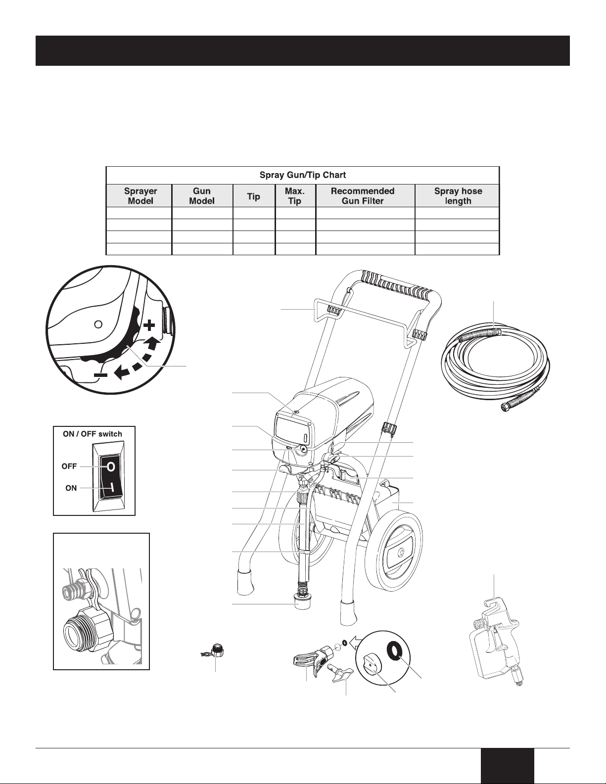
Components and Description
1620
1720
1920
GX-07
GX-07
GX-08
415
517
517
517
519
521
Yellow (fine)
1420 GX-05 415 415 Yellow (fine)
White (medium)
White (medium)
25 feet
25 feet
50 feet
50 feet
*Saddle seat and washer
come pre-assembled
inside spray guard
Saddle
seat*
Washer*
Oiler (1620, 1720
and 1920 only)
Spray hose port
(reverse side)
Pail bracket
Oiler button
Pusher stem
Suction set filter
Suction tube
Return tube
Clip
Hose bracket
PRIME/SPRAY knob
ON / OFF switch
Cord wrap / Tip holder (1620,
1720 and 1920 only)
To olmate™ Tool box
(1720 and 1920 only)
Spray hose
Spray gun (see chart above
for models, GX-07 shown)
Spray guard
Spray tip (see
chart above
for models)
**The pump cleaning
adapter can be clipped
to the spray hose port
Pump cleaning
adapter**
Pressure control dial
(rear of sprayer)
This pump is available in a stand model (1420) and cart models (1620, 1720 shown below, and 1920). All information given
or the stand model applies to the cart models except where indicated.
f
Important
Some of the graphics in this manual may not exactly match your sprayer and spray gun. All information and instructions
given in this manual applies to all models except where noted.
5
English
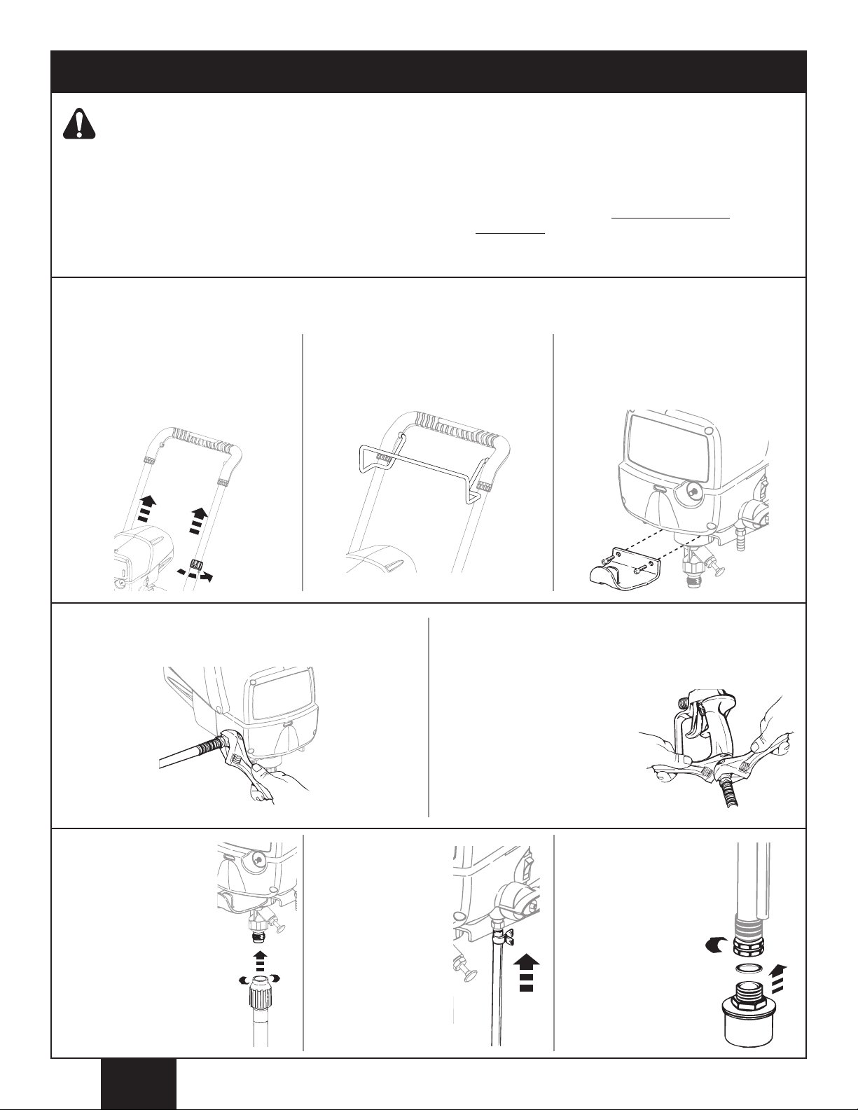
Do not plug in the sprayer until setup is complete.
Tools needed for assembly:
Assembly
Two adjustable wrenches
•
• 3/16” Allen wrench
f you have one of the cart models (1620, 1720 or 1920), follow these assembly instructions. If you have the model 1420
I
sprayer, skip to item 4, below.
1. Twist the knobs on either side of the
counterclockwise to unlock
handle
the handle. Pull the handle out fully,
and turn knobs
into place.
clockwise to lock
2. Insert the ends of the hose bracket
into the holes of the handle as
shown.
Extension cord (refer to Important Electrical
•
Information (page 3).
3. Attach the pail bracket. Line up the
holes in the bracket with the holes in
the sprayer. Insert and tighten the
screws using a 3/16” allen wrench.
4. Thread the high pressure hose to the spray hose port.
Tighten with an adjustable wrench.
6. Thread the suction
tube onto the inlet
valve and tighten
firmly by hand. Be
sure that the threads
are straight so that
the fitting turns freely
.
Press the return
7.
tube onto the
return tube fitting.
Squeeze clip
over the return
tube fitting to
secure the return
tube.
5. Thread the other end of the hose to the spray gun. Hold
the gun with one adjustable wrench, and tighten the hose
nut with the other.
The spray tip SHOULD NOT
be attached until after the
sprayer and spray hose have
been purged and primed.
erify that the seal is
V
8.
present inside the
suction tube. Thread
the inlet filter into the
end of the suction
tube.
English
6
Before you begin -
O
O
SPRAY
PRIME
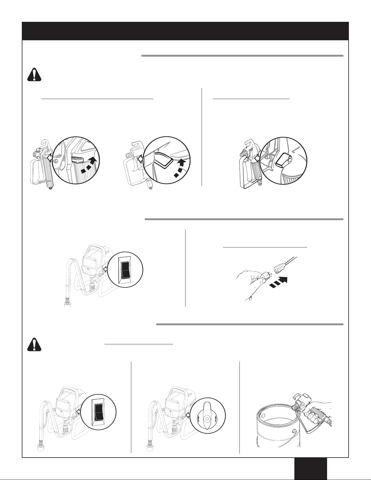
Locking the Spray Gun:
Always lock the trigger off when attaching the spray tip or when the spray gun is not in use.
This section contains instructions that
will be repeated throughout this manual.
Model GX-05 and GX-07 Spray Gun
he gun is locked when the trigger lock is at a 90º angle
T
(perpendicular to the trigger in either direction).
GX-05 GX-07
Plugging in the Sprayer:
1. Check that the ON/OFF switch is in the OFF (O) position.
Model GX-08 Spray Gun
To lock the gun, turn the trigger lock forward and
slightly down until it stops.
2. Plug the power cord into a grounded outlet or heavy duty
grounded extension cord. Plug in the extension cord.
Refer to Important Electrical Information, page 3.
Pressure Relief Procedure:
Be sure to follow the Pressure Relief Procedure when shutting the unit off FOR ANY PURPOSE. This
procedure is used to relieve pressure from the spray hose.
Lock the spray gun of
1.
directions above). Flip the
ON/OFF switch to the OFF position.
f
(see
2.
T
PRIME.
urn the PRIME/SPRA
7
Y knob to
Unlock the spray gun and trigger
3.
spray gun into the side of the
material bucket. Lock the spray gun.
English
(a)
Purging and Priming the Sprayer
l
(b)
(a)
SPRAY
PRIME
All new units are performance-tested at the factory and are shipped with test fluid in the fluid section to prevent
orrosion during shipment and storage. If you have already used your pump, some water or solvent used in cleaning
c
may remain in the fluid section. Whether your sprayer is new or if you have already used it, this fluid must be purged
nd thoroughly cleaned out of the system prior to use. Follow the steps below.
a
1620, 1720 and 1920 only.
1. Remove oiler cap using a straight-slot
screwdriver. Squirt separating oil P/N
0516915 supplied with your sprayer
nto the oiler (approximately 1 ounce).
i
Light household oil can be substituted
if necessary. Replace cap.
2. After filling, push button on front of
face plate 2-5 times to lubricate the
fluid section. Press
ight hours of usage. Be sure to
e
check reservoir level
necessary.
once for every
(a) and refill as
3. Fully depress the pusher stem to
make sure the inlet ball is free.
4. Place a full container of spraying material underneath the
suction tube (a). Secure the return tube (b) into a waste
container.
6. Plug in the sprayer and move the ON/OFF switch to the
ON (l) position.
5. Turn the pressure control dial to maximum pressure (+).
Turn the PRIME/SPRAY knob to PRIME.
7. Switch the pump OFF (O).
the waste container and place it in its operating position
above the container of spraying material. Use the metal
clip to bind the two hoses together.
Remove the return tube from
The unit will begin to draw material up the suction tube,
into the pump, and out the return tube. Let the unit cycle
long enough to remove test fluid from the pump, or until
spray material is coming from the return tube.
English
8
O
SPRAY
PRIME
Purging and Priming the Spray Hose
SPRAY
PRIME
Begin
tightening
the tip at
this angle
. . .to achieve
the desired
spray angle
when tight.
SPRAY
PRIME
1. Unlock the spray gun and turn the PRIME/SPRAY knob to
PRIME.
he spray tip SHOULD NOT
T
be attached to your spray
un when purging your
g
spray hose.
PULL the trigger and aim the spray gun at the side wall of
2.
a waste container.
pray gun must be grounded while purging (see
s
If using oil-based materials, the
warning below).
Keep hands clear from fluid stream.
Ground the gun by holding it against the
edge of a metal container while flushing.
Failure to do so may lead to a static electric
discharge which may cause a fire.
3. While pulling the trigger, switch the pump ON (l), AND
turn the PRIME/SPRAY knob to SPRAY. Hold the trigger
until all air, water, or solvent is purged from the spray
hose and material is flowing freely.
If the PRIME/SPRAY knob is still on SPRAY,
there will be high pressure in the hose and
spray gun until the PRIME/SPRAY knob is
turned to PRIME.
4. Release trigger. Turn the PRIME/SPRAY knob to PRIME.
Turn the pump OFF (O). Trigger the gun into the waste
container to be sure that no pressure is left in the hose.
5. Lock the spray gun off. Make sure the saddle and
black seal are in place inside the tip guard nut (refer
to Components and Description
, page 5). Thread the
spray tip guard assembly onto the gun. Tighten by hand.
9
English
 Loading...