

Page 1
Page 2
Page 3
Page 4
Page 5
Page 6
Page 7
Page 8
Page 9
Page 10
Page 11
Page 12
Page 13
Page 14
Page 15

Page 16
Page 17
Page 18

SPRAGUE TO-5 AND -6 CALIBRATION (with notes on TO-4 similarities)
CAPACITANCE MEASUREMENT CALIBRATION by DavidK
Note: Some models may have fixed or variable resistors in the R12 or R14 positions to expand the ends
of the ranges. If your dial settings do not track properly, it may be helpful to add trimmers in these
locations. See details below.
Caution: The TO-5 circuit uses high voltages for many of its tests. ALWAYS release all the black and red
buttons before connecting or removing a capacitor. (This disables the test voltages and discharges the
capacitor.)
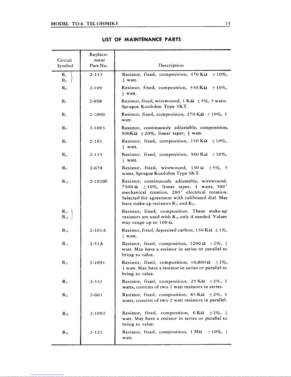
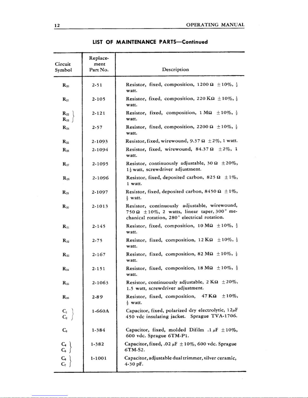
1. Recap/repair/restore unit, check resistors where possible, verify normal operation. Be sure to install
measured, precise replacements for C8 (.02 UF ) and C9 (2 UF).
2. Prepare the following 11 capacitors. As capacitor tolerances vary greatly, only measured, precise
capacitors should be used. In some cases you’ll need to use parallel (or series) capacitors.
Range C1-2: lower 10 PF, center 200 PF, upper .005 UF
Range C3: lower 1000 PF, center .02 UF, upper .5 UF
Range C4: lower .1 UF, center 2 UF, upper 50 UF
Range C5: lower 50 UF, center 80 UF, upper 2000 UF.
If possible, use an oscilloscope or VTVM for calibration. This will be easier and more accurate than using
the eye indicator. Connect your scope or meter to chassis ground and the + terminal of the TO-5. A
balanced bridge condition is indicated by lowest level (deepest AC null). Remember that with some
capacitors, the Power Factor control must be adjusted to get accurate readings.
3. Start by aligning Range C3. Check dial reading with the .02 UF cap, loosening the dial setscrew and
re-positioning dial for exact reading, (Perform this step very carefully, it will affect everything else.) Then,
check with 1000 PF cap. The reading should be very close. If the dial reads high with the 1000 PF cap,
optional trimmer R14 can compensate. (If the dial reads low, this suggests a problem in the unit.)
Next, check the upper part of the range using the .005 UF cap. The reading should be very close. If the
dial reads low, optional trimmer R12 can compensate. (If the dial reads high, this suggests a problem in
the unit.)
Recheck dial indications with all three capacitors.
4. Check Range 4 using the .1, 2 UF, and 50 UF caps. The readings should be very close.
5. Check Range 5 using the 50 UF, 80 UF, and 2000 UF caps. The readings should be very close. If this
range is off ‘across the board”, improvement is possible by replacing R15 (150K) with a 200K trimmer.
(R15 only affects this range.) Set the trimmer to 150K, connect the 80 UF cap, set the dial for 80 UF, and
then adjust the trimmer for balanced condition. Recheck with the 50 UF and 2000 UF caps, readings
should be very close.
6. Align Range C1-2. This sensitive adjustment has been saved for last, so that the unit can be “left as is”
afterwards. Connect the 200 PF cap, set the dial for 200, and adjust trimmer C7 for balanced condition.
(C7 only affects this range.) Check with the 10 PF and 5000 PF caps, readings should be very close. If
the dial reads low with the 10 PF cap, a 1-3 PF capacitor can be soldered to the to the - / + binding posts
to trim this reading. A trimmer or “gimmick” capacitor could also be used.
Page 19

At this point it would be good to recheck other ranges, though none of these steps should affect any
previous ones. Then - done!
-------------------------------------------------
Note 1: R12 and R14 may have been added to the bridge pot during production. R12 would have been
added to the clockwise end of the pot to expand range on the upper side of the dial, and R14 would have
been added to the counter-clockwise end of the pot to expand range on the lower side. These resistors
may be replaced with 100 ohm trimmers to correct range "spread" problems. To install the trimmers
measure the existing resistors with an accurate ohm meter, then set the new trimmers to match the old
fixed resistors. Install the R12 trimmer between the clockwise terminal of the pot and R10 (150 ohms, 2
watts) and install R14 between the counter-clockwise terminal of the pot and the wire to the switch board.
Note 2: It is advisable to add back to back protection diodes (1N4007 or similar) across the meter for
overload protection.
Note 3: When using the TO-5, readings in the center of the dial will be the most accurate.
Some notes about the circuitry:
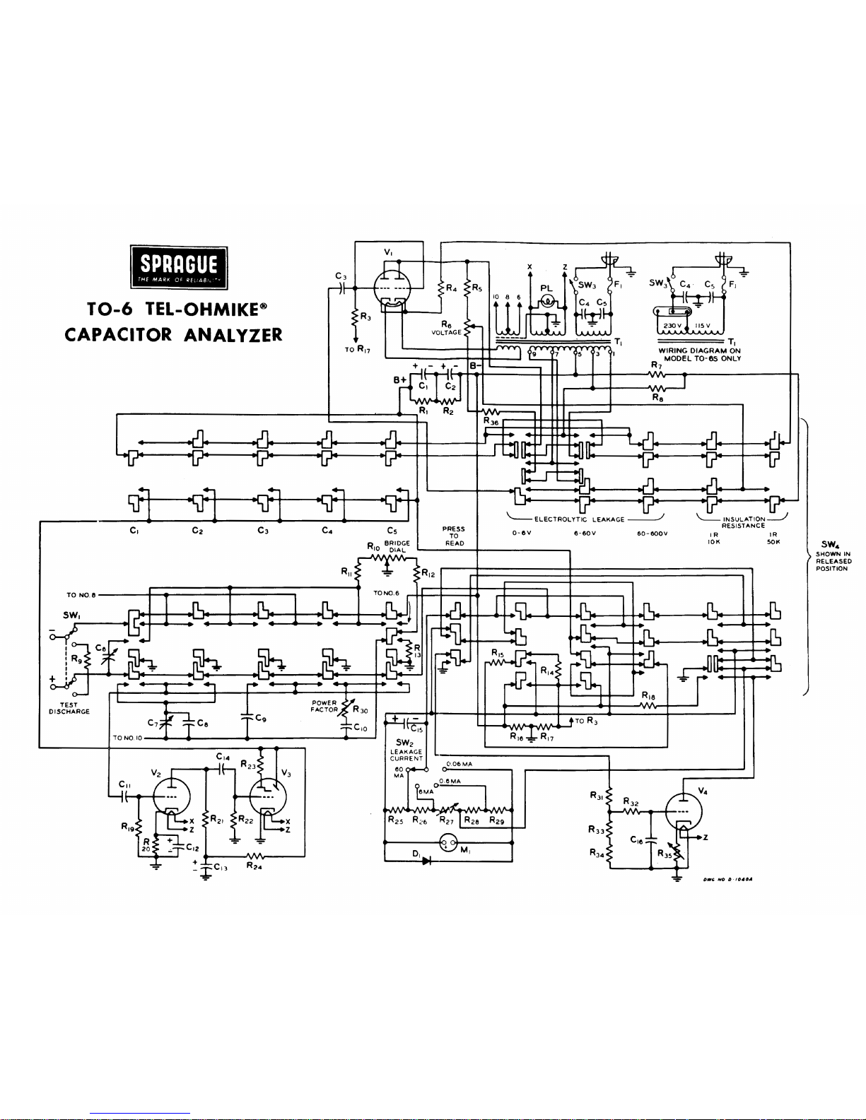
C1-2 range reference is C6 (180 PF) with C7 trimmer.
C1 range accuracy is +/-2% and +/- 1 PF
C2 range accuracy is 3%
C3 range reference is C8 (.02 UF)
C3 range accuracy is 5% from .001 to .005 and 3% from .005 to .1
With C3 range selected, R11 is inserted between the upper side of the range control and the power
transformer. In all other ranges R11 is bypassed.
C4 range reference is C9 (2 UF)
C4 range accuracy is 5% from .1 to .5 and 3% from .5 to 10 UF
C5 range reference is C9 (2 UF), extended by shunt resistor R15 (150K).
R12 is an optional selected resistor on the upper side of the bridge dial, 0-100 ohms. Increasing the
resistance of R12 will expand range at the upper side of the dial. (With R12 or R14 at 100 ohms, about
1/4” of “dial diameter” is added.)
R14 is an optional selected resistor on the lower side of the bridge dial. Increasing the resistance of R14
will expand range at the lower side of the dial.
ELECTROLYTIC LEAKAGE TEST by Leigh
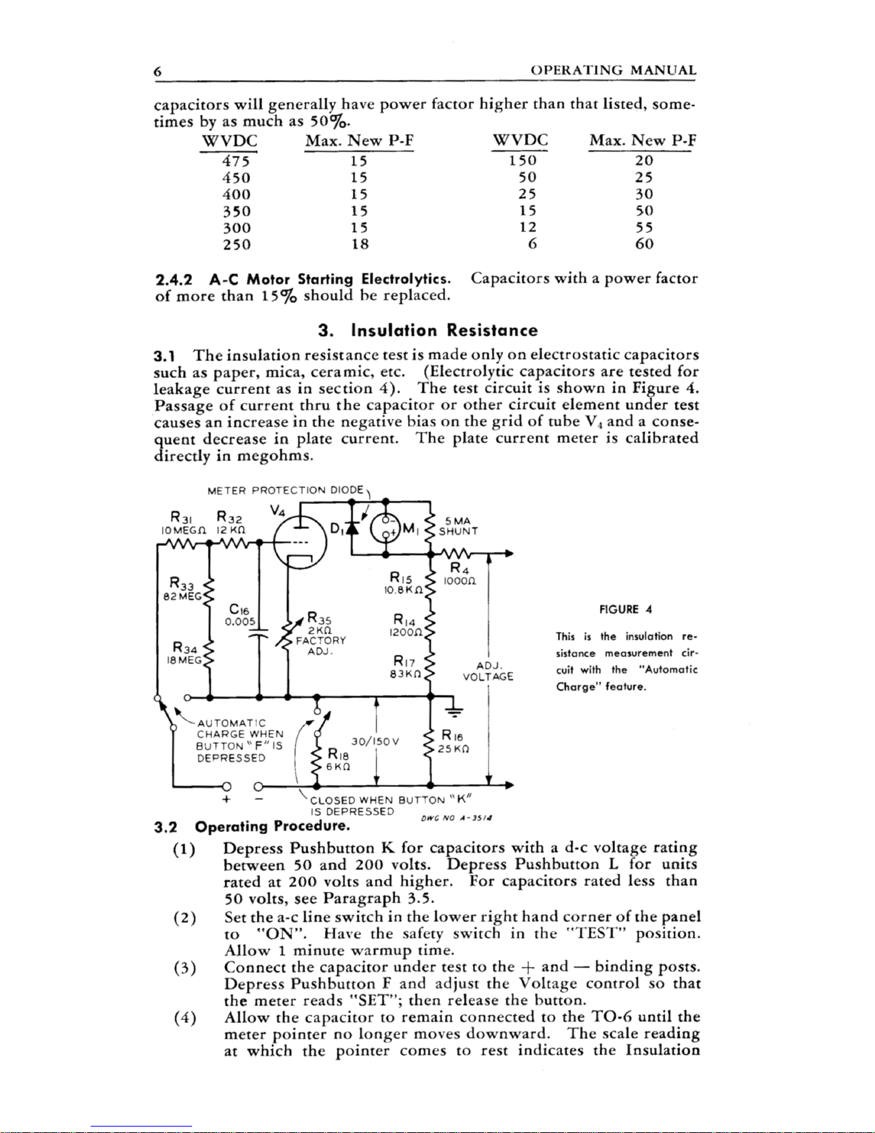
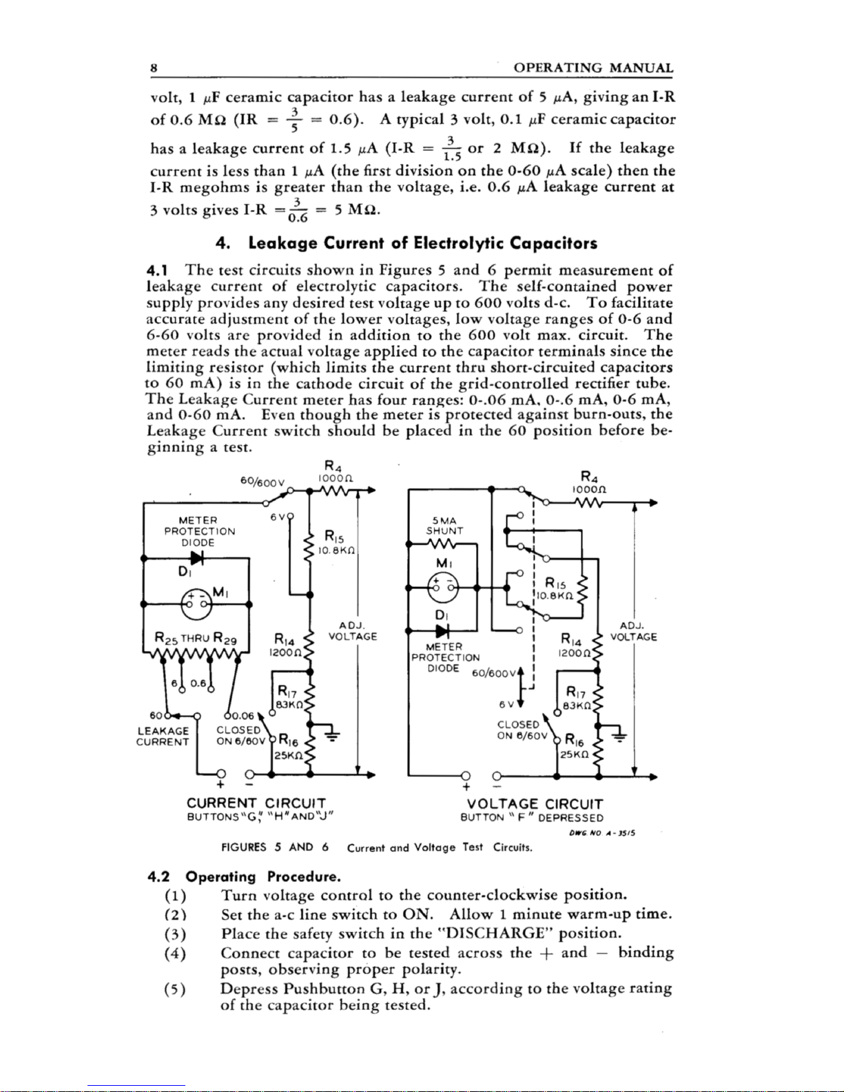
The 5 mA shunt on the TO-6 sets the current flowing through the metering resistors. The sum of the
metering resistances R14, R15, R16, and R17 is 120000 ohms. If you apply 600 volts across 120K, you
draw 5 mA of current. In the case of the TO-6, a small portion of the 5 mA flows through the meter, and
the remainder through the 5 mA shunt.
To set the shunt, select the 600-volt range and connect a digital voltmeter to the binding posts. Depress
button F and adjust the TO-6 voltage control for 600 volts on the DVM. Then adjust the shunt for a fullscale (600 volt) reading on the meter. Check the full-scale voltages on the 60- and 6-volt ranges. If they're
off, check metering resistors R14 and R15 and replace any that are off value.
Page 20

INSULATION RESISTANCE TEST CALIBRATION by Erik
Make sure the 5mA meter shunt is correctly set before doing this (see above). Start on the higher voltage
range ("L"), and adjust the meter to "Set" using the "F" button. Connect a VERY large resistor, preferably
a value that is near the middle of the meter scales (several hundred megohms, potentially available from
inside an old high voltage probe), to the test terminals. Adjust pot R35 to establish the correct meter
reading to match the value of the resistor you're using.
Switch to "K" range and readjust the meter to "Set" while holding in "F." Potential showstopper: if your
R18 is only a fixed resistor, you'll have to change it to a pot or combination fixed and pot to calibrate the
"K" range. Vary the resistance of R18 to establish the correct meter reading for your resistor. Double
check the "L" range, which shouldn't have been affected, and you're done.
NOTES ON SPRAGUE TO-4 by DavidK
Electrically the capacitance measurement circuits are nearly the same, and it looks to me as if the TO-5
procedure should work on the others.
However, the parts designations are different, which might be confusing. These are the differences that I
see:
1. The C1-2 reference capacitor,C-6 (180 PF) on the TO-5 is C-3 on the TO-4 and C-8 (changed to 190
PF) on the TO-6.
2. The C3 reference capacitor (.02) is C-8 on the TO-5, C-4 on the TO-4, and C-9 on the TO-6.
3. The C4 and C5 reference capacitor (2 UF) is C-9 on the TO-5, C-5 on the TO-4, and C-10 on the TO-6.
4. The 150k shunt resistor that extends the hi UF range is R-15 on the TO-5, R-6 on the TO-4, and R-13
on the TO-6.
In addition to those noted, the procedures above also include the assistance and expertise of Chris H and
Dave H (easyrider8).
 Loading...