

SP POWERWORLD EG3000 User Manual
SP POWERWORLD LTD
Willows, Waterside, Ryhall, Stamford, Lincs, PE9 4EY, UK Tel:
+44 (0) 115 9232568 - Email: info@sp-powerworld.com
www.sp-powerworld.com
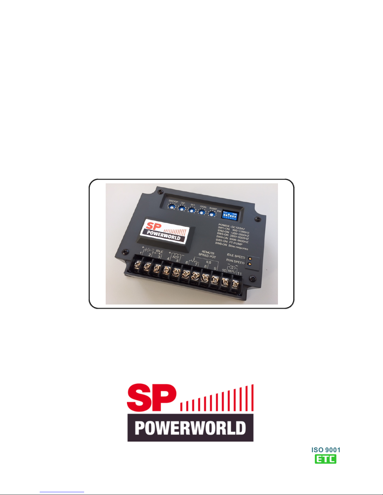
EG3000
Electronic Engine Governor Controller
User Manual
Engine Start Smoke Limiting function & IDLE Speed Setting
For External, Built-in, PT-Pump type and hydraulic drive actuators
Newly added “extreme slow response” engine setting
___________________________________________________________________________________________
2
EG3000
SECTION 1 : SUMMARY
The EG3000 electronic controller takes a signal from a magnetic pickup (MPU) and compares it with a preset engine
speed to control drive voltage to the actuator to maintain constant engine speed. The EG3002 has engine start
smoke suppression, IDLE Speed control, Ramp Time setting, applicable for MPU frequency range of 600 to 9500 Hz.
The unit has settings for use with Cummins high-gain (PT PUMP) engines and “extreme slow response” engines.
SECTION 2 : SPECIFICATION
Operating Voltage ( Terminals 1, 2 ) Speed Droop
Voltage 10 − 32 Vdc 0 − 4% (adjustable)
Outputs ( Terminals 4, 5 ) Stability
Voltage Max. 95% of Input Voltage Speed variation less than +/- 0.25% at constant load
Current Continuous 7A min. 0.5A
Max. 15A 10 seconds Static Power Consumption
Less than 1 Watt @ 12 Vdc
MPU Signal ( Terminals 10, 11 ) Less than 2 Watt @ 24 Vdc
Frequency 10 – 10,000 Hz
Voltage 1 – 120 Vac (RMS) Speed Temperature Shift
Less than 3% at temperature range -40 to +80 ˚C
Frequency Adjustment
Speed Adjustment pot (25 turn) Environment
Setting range 600 – 9,500 Hz (With DIP Switch) Operating Temperature -40 to+80 ˚C
Storage Temperature -40 to +85 ˚C
Remote Speed Potentiometer ( Terminals 6, 7, 9 ) Relative Humidity Max. 95%
Max. +/- 7% @ 5 KΩ 1 watt potentiometer
Vibration 5.5Gs @ 60 Hz
Isochronous Load Sharing (ILS) ( Terminals 6,8 ) Dimensions
Input Resistance greater than 2 KΩ 147.0 (L) x 114.0 (W) x 50.0 (H) mm
Input Ranges -5 Vdc to +5 Vdc / 0 to 10 Vdc 5.79 (L) x 4.49 (W) x 1.97 (H) inch
Sensitivity 15%@10 Vdc
Weight
IDLE Control ( Terminals 2, 3 ) 690 g +/- 2%
Adjustment range 30 – 90% of Normal Speed 1.52 lb +/- 2%
Ramp Time
3 − 20 seconds (adjustable)
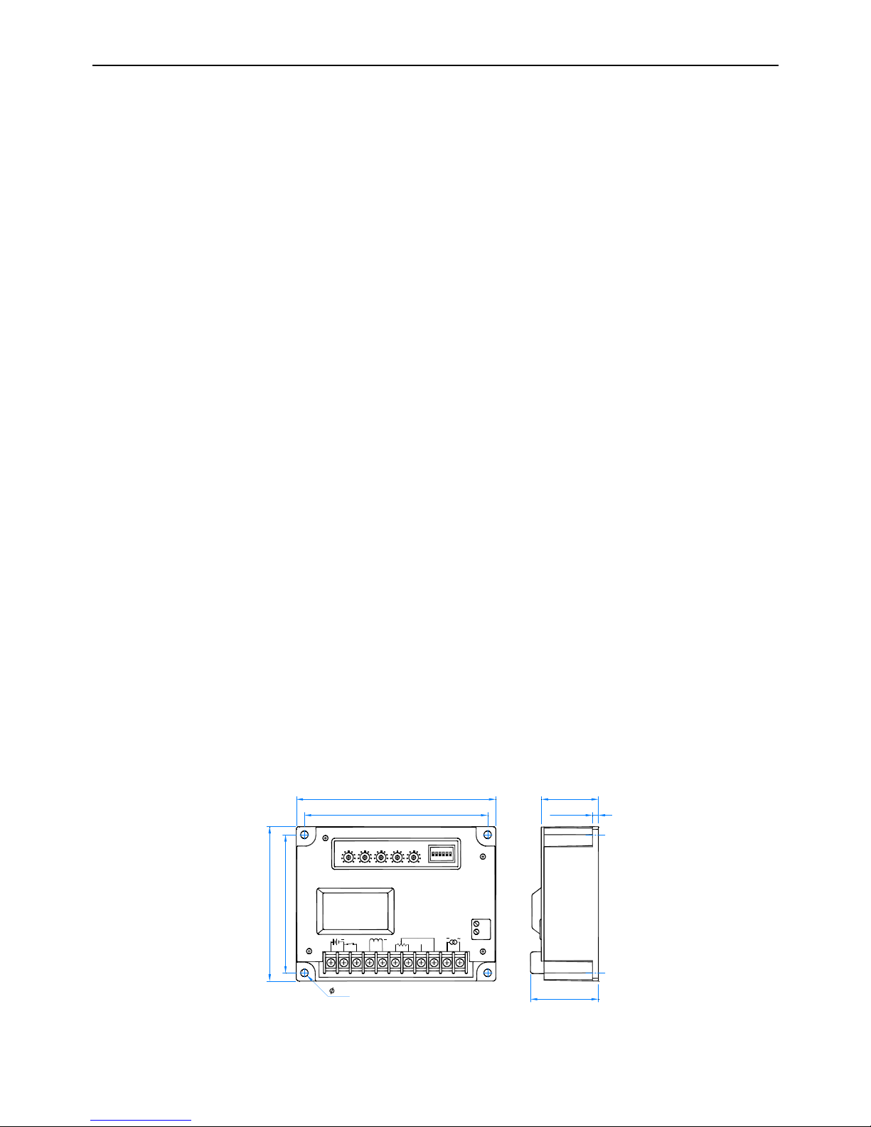
SECTION 3 : APPEARANCE / DIMENSIONS / INSTALLATION DRAWING
DROOP DIF. INT. GAIN RAMP
IDLE
1 2 3
ACT
4 567
MPU
9
ILS
8 10 11
+
REMOTE
SPEED POT RUN SPEED
IDLE SPEED
135.0 [5.31"]
147.0 [5.79"]
102.0 [4.02"]
114.0 [4.49"]
5.5
4.0 [0.16"]
40.0 [1.57"]
50.0 [1.97"]
Unit : mm
[inch]
SW1-ON 600~1200HZ
S
W2-ON 1200~2500HZ
SW4-ON 5000~9500HZ
SW3-ON 2500~5000HZ
POWER : DC12/24V
SW5-ON PT-PUMP
SW6-ON Slow response
SW
+
Figure 1 Outline Drawing
___________________________________________________________________________________________
EG3000
3
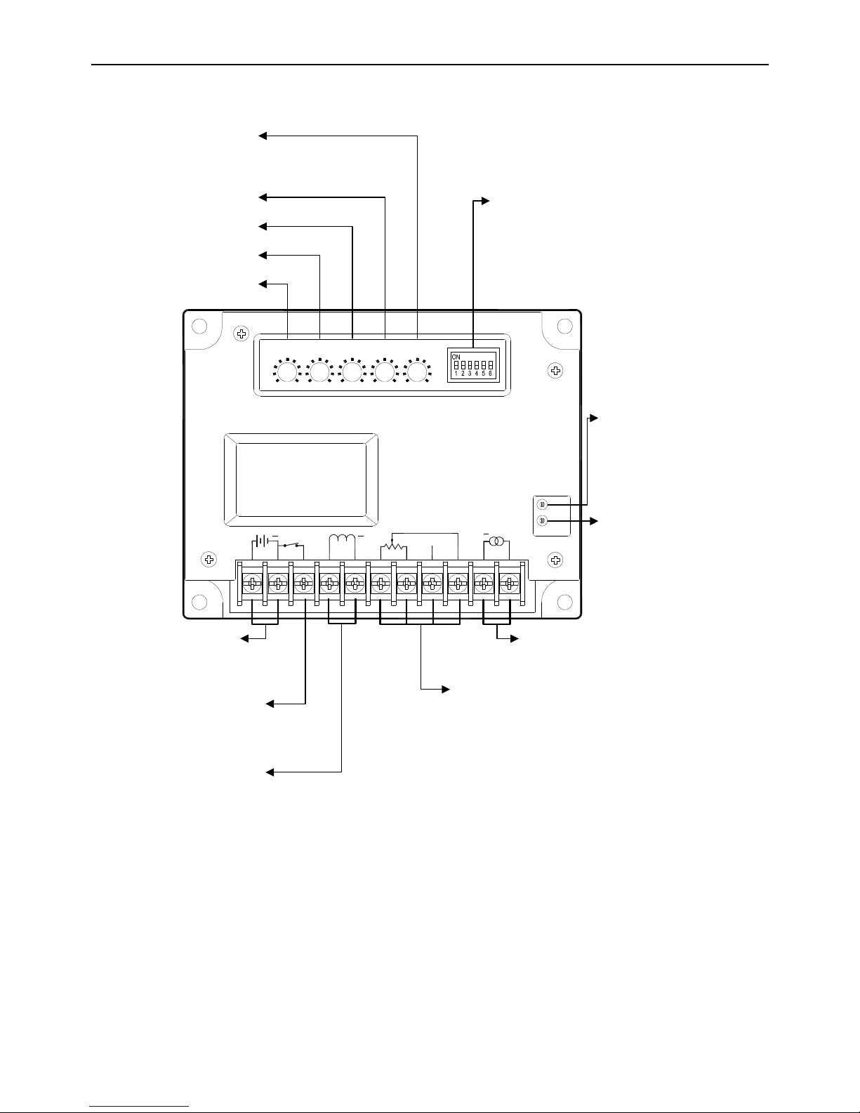
SECTION 4 : POTENTIOMETER ADJUSTMENTS AND DIP SWITCH FUNCTIONS
DIP Switch Functions
SW 1 to 4:Frequency Range Selection
SW 5 ON:Cummins PT PUMP
SW 6 ON:
Extreme Slow Response engines
IDLE SPEED:IDLE
Speed
Setting
When Terminals 2 & 3
shorted, use this pot
to
adjust IDLE speed.
RUN SPEED: O
perating
Speed Setting
10、11:MPU Input
Use shielded cable
6、7、9:Remote Speed Potentiometer
Connect a 5 KΩ potentiometer. Must use s
hielded
cable.
6、8:Isochronous Load Sharing (ILS) Input
Analog input signal from the load sharing controller
.
Must be isolated from battery power
. Terminal 6 is
ground of load sharing controller
. Terminal 8 is
input signal from controller.
1、2:Battery Input
Connect to genset battery.
Use14 AWG wire or larger
3:IDLE Control Contact
When shorted to t
erminal 2 unit
will go to
IDLE state.
4、5:Output to Actuator
Use 14 AWG wire or larger
INT:Integral Setting
DIF:Differential Setting
DROOP:Speed Droop
Setting
GAIN:Gain Setting
RAMP:Ramp Time
Time for engine speed to climb from IDLE to
operating speed. (3 to 20 seconds)
DROOP DIF. INT. GAIN RAMP
SW1-ON 600~1200HZ
SW2-ON 1200~2500HZ
SW4-ON 5000~9500HZ
SW3-ON 2500~5000HZ
POWER : DC12/24V
IDLE
1 2 3
ACT
4 5 6
7
MPU
9
ILS
8 10 11
~
+
REMOTE
SPEED POT
RUN SPEED
IDLE SPEED
SW5-ON PT-PUMP
EG3000
+
SW6-ON Slow response
SW
 Loading...