

SP POWERWORLD EA08A/RS Operation Manual
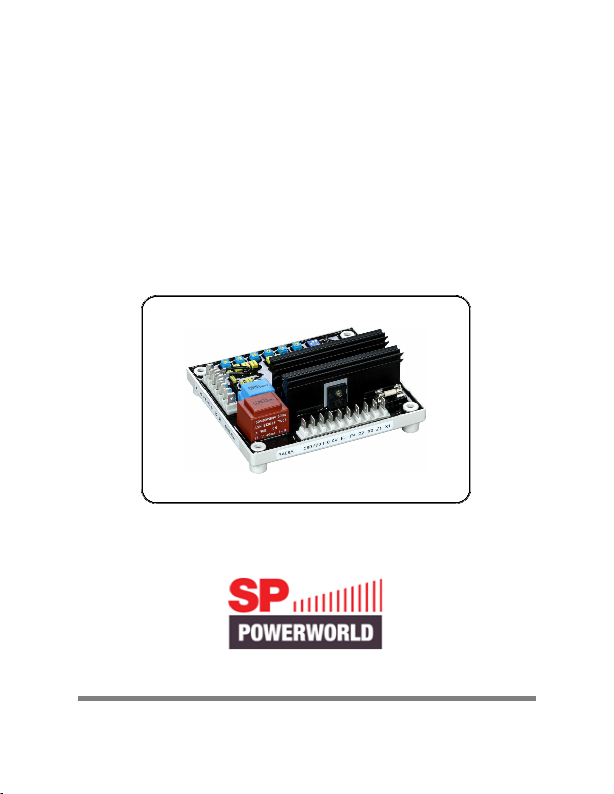
EA08A/RS
Generator Automatic Voltage Regulator
Operation Manual
Self Excited Automatic Voltage Regulator for use in Brushless, Full
Harmonic or Harmonic and Auxiliary Winding.
Compatible with the Leroy Somer RS128 A & RS128-0.
This component must be housed inside alternator terminal box and be fitted by a competent electrical engineer.
SP POWERWORLD LTD
Willows, Waterside, Ryhall, Stamford, Lincs, PE9 4EY, UK Tel:
+44 1780 756872 - Email: info@sp-powerworld.com
www.sp-powerworld.com
______________________________________________________________________________________
2 EA08A
UF
ON
1
380
UFRO
3-ON,60Hz
1-Different
2-Integral
Z1X1 X2
LAMSTAB DROOP
0VF+Z2 F- 110 220
S2
TRIMVOLT
A2
A1
VRVR S1 S3
1. INTRODUCTION
Sensing Input
Terminal 0 ~ 110V = 95 ~ 135V
Terminal 0 ~ 220V = 180 ~ 250V
Terminal 0 ~ 380V = 360 ~ 515V
Frequency 50/60 Hz, Jumper selectable
Harmonic Voltage
Voltage 25 ~ 300VAC
Voltage Regulation
< ±0.5% (with 4% engine governing)
Voltage Build-up
Harmonic Residual Volt. > 5 VAC
Output Voltage
Maximum 90VDC @220VAC
Output Current
Maximum Continuous 8 A
Intermittent 12 A for 10 sec
External Volts Adjustment
±10% @ 1KΩ
X1、、、、X2 Z1、、、、Z2
45 ~ 600HZ
Thermal Drift
0.05% per ℃ change in AVR ambient
Analog Voltage Input
10% generator voltage per 1VDC
Current Compensation
N : 5 A or N : 1A Input
Maximum 4% @ P.F. = 0.8
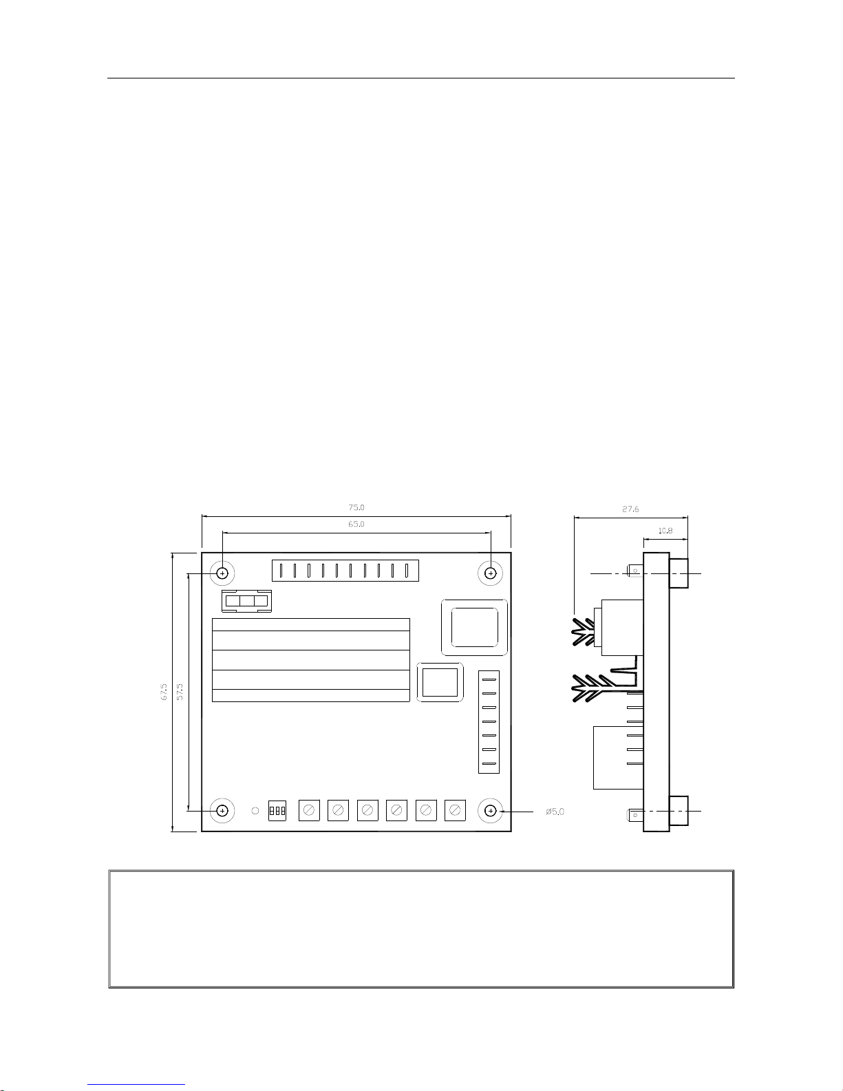
Dimensions
150mm L * 135mm W * 55.3mm H
Weight
600g ± 5%
Mechanical Specifications
AVR can be mounted directly on the engine, genset, switchgear or control panel that conforms to the
mounting specification.
All voltage readings are to be taken with an average-reading voltmeter Meggers and high-potential test
equipment must not be used. Use of such equipment could damage the AVR.
Figure 1 Outline Drawing
 Loading...