

Spot Welder TSP-1, TSP-2, TBW Owner's Manual
Spotwelder
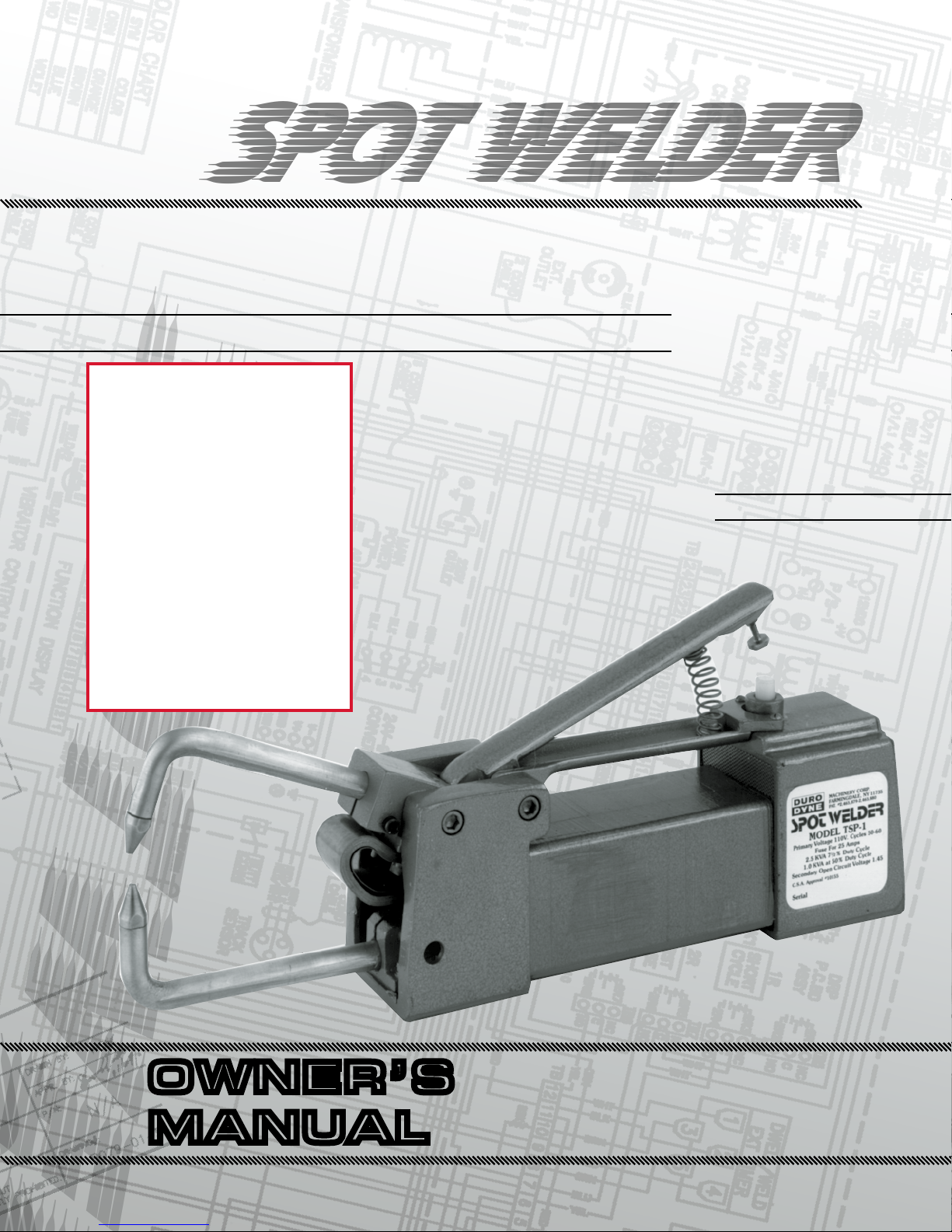
Spot Welder
Spot Welder
Spot Welder
ModelS tSp-1/tSp-2/tbW
Owner’s Manual for
TSP1:
SN# 21809 and below
TSP2:
SN# 30897 and below
TBW:
SN# 41001 and below
Approx:
July ‘13 and earlier
MACHINerY
dIVISIoN
oWNer’S
MANUAl
INTRODUCTION
CONTROL SCREW ADJUSTMENT
Duro Dyne Spot Welders have over 50 years of proven
reliability in shop environments. The latest models, TSP/
TBW, incorporate the established durability with a built
in solid state timer for weld accuracy and consistency.
Optional accessories such as water cooled arms and the
ST-2 Spotwelder Stand mean the TSP/TBW Spot Welders
can be customized for your special needs in producing a
top quality product.
To avoid unnecessary problems while using your TSP/TBW
Spot Welder, please read this instruction manual fully and
understand its contents completely.
IMPORTANT: Always follow manufacturer’s recommendations for proper safety and handling procedures for all
materials used in conjunction with this machine as outlined
in Manufacturer’s Safety Data Sheet (MSDS) for each
product.
ELECTRICAL INSTALLATION
MODEL TSP-1 - 110V - Fuse for 25 amps
MODEL TSP-2 - 220V - Fuse for 15 amps
MODEL TBW - 220V - Fuse 25 amps
Connect the welder to a lightly loaded circuit supply line.
For best results: Use a separate line as voltage drops can
severely affect the efficiency of your welder.
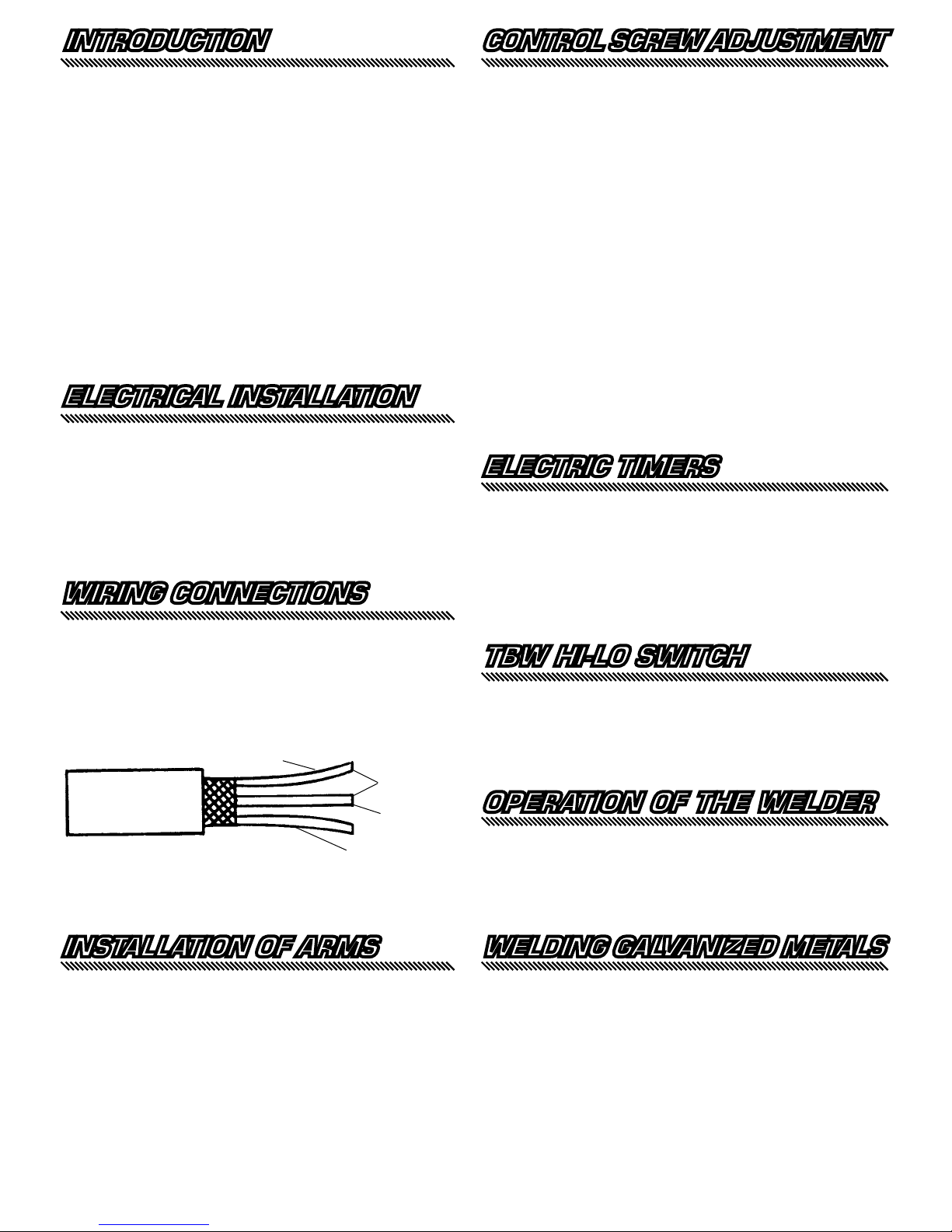
WIRING CONNECTIONS
Welders are normally supplied with a 3 prong polarized plug
to insure that the body of the welder is grounded. This is
a safety precaution which should be taken on all electrical
tools. In the event that you wish to use a plug other than
the one supplied, the following diagram shows the welder
connections:
white
connect
to power
black
green to
ground
Located on the underside of the welder handle, towards the
back is a small, knurled screw. This screw determines the
point at which the welder is activated after the welding tips
are brought together against the metal. This switch control
screw should be adjusted as follows:
1. Place metal between welding tips. Squeeze handle,
applying moderate pressure to the welding tips.
Current should NOT yet be “ON.”
2. Loosen jam nut. Adjust switch screw up or down, as
the case may be, so that further pressure on the
handle will activate switch and apply current. Tighten
jam nut to lock adjustment.
3. This setting is changed only if the thickness of the
metal being welded is changed greatly, or to compen-
sate for the dressing of the tips.
NOTE: In some cases the range of switch adjustment
may not be sufficient for proper setting. To adjust for new
arms, remove the upper arm, place back end in a vise and
bend slightly in the direction necessary to allow for proper
adjustment.
ELECTRIC TIMERS
All TSP and TBW welders are supplied with solid state
timers. The timer allows complete control of the welding
cycle to assure fast and quality welding on even very light
gauge steel. When properly adjusted the timer will eliminate
“burn through.”
The timer is adjustable from 1/10th to one (1) second. To
adjust, simply turn the knob on the back of the welder until
the desired time is set ( counterclockwise to decrease;
clockwise to increase).
TBW HI-LO SWITCH
When welding extremely light gauge metal the power of the
TBW may be too hot to avoid “burn through.” To “cool down”
the TBW, a Hi-Lo switch was installed. When welding light
gauge steel simply “flip” the Hi-Lo switch to Lo and adjust the
timer as usual. Be sure to change the switch to Hi when going
to heavy gauge or difficulty in welding will be experienced.
OPERATION OF THE WELDER
It is suggested that before using the Spot Welder on regular
work, the operator should try welding pieces of scrap metal
similar to the production material in order to determine the
length of time it takes for proper fusion of the metals. The
heavier the thickness of metals to be welded, the longer the
timer must be on to perform a satisfactory weld.
INSTALLATION OF ARMS
The arms of your welder should be inserted as follows:
1. Loosen slightly the 1/4-20 Allen Head Cap Screw on
the side of the “nose piece.” Insert top arm (shorter
arm) all the way in, seat firmly and tighten screw.
2. Loosen slightly the 1/4-20 Allen Head Cap Screw on
the side of "lower arm mounting" (hole in side of front
body allows easy access). Insert lower arm deep
enough so that tips meet exactly when arms are
brought together. Tighten screw.
3. Recheck the alignment and readjust as necessary.
WELDING GALVANIZED METALS
Since the galvanized coating is a poor conductor of electricity,
it does not weld as readily as uncoated metal. The following
simple procedure is suggested when welding galvanized iron:
1. As soon as current is applied, tilt the work so that the
tips can “bite” into the coating. This will start the weld.
2. Keep handle depressed until weld cycle is complete. In
cases of metal which is rusty or has a heavy scale,
cleaning is recommended before welding.
In all cases, materials being welded should be clamped
together so it will not be necessary for the arms to pull
the material together.
 Loading...