

Page 1
S
potCell
™
100
Quick Installation Guide
www.spotwave.com
Spotwave Wireless Inc. 3701 Carling Avenue, Ottawa ON K2H 8S2 Canada
Tel: (613) 820-0023 Fax: (613) 828-1956 E-mail: [email protected]
© 2001 Spotwave Wireless Inc. All rights reserved. Printed in Canada
Page 2
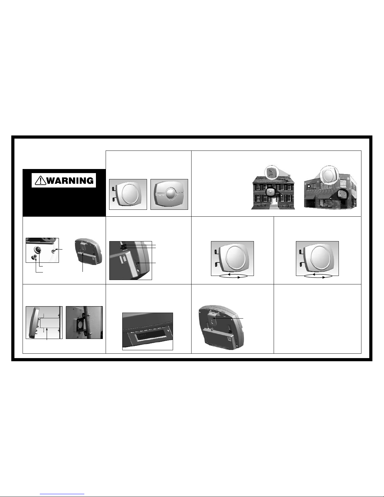
4. Installation
Set the switch on the bottom of the SCU to “1” (install).
Connect the power supply to the SCU, then plug the adapter
into the AC outlet.
If required, more detailed information on installing
SpotCell 100 can be found in the enclosed Installation
Manual.
5. Installation: DDU
In the location where the DDU is to be mounted, rotate the
unit in a complete circle. The LED on the back will turn red
or green during the rotation.
6. Installation: DDU
Again rotate the DDU. When the LED turns green, stop the
rotation. This is the direction the DDU must face when
mounted.
9. Installation: SCU
Mount the SCU from a wall or ceiling, close to the centre
of the area requiring coverage.
2. Location
The DDU can be mounted anywhere
your cell phone works. This may be on
a rooftop (typical rural set-up), on the
side of a building, or inside a building
(typical downtown set-up). The SCU
will be mounted inside the building
where your cell phone does not work.
(The illustrations at the right depict
typical installations.)
To start the installation, place the
DDU and SCU in the general areas
where they are to be located. Do not
physically mount them at this time.
3. Installation
Connect the DDU and SCU with the cable provided.
For quick installation of SpotCell 100:
For your safety, beware of power lines and ensure that
appropriate safety measures are maintained at all times
during the installation of the SpotCell 100 equipment.
Contact with high-voltage power lines could result in death
or serious injury.
10. Final Checklist
1. Properly ground the DDU via the grounding bolt.
2. Ensure that there is a drip loop on the cable connecting
to the DDU.
3. Firmly affix the cable to the building where it runs
between the DDU and SCU.
8. Installation: SCU
Move the switch on the bottom of the SCU to “2” (active).
Hold the SCU in the location to be mounted. The LCD on
the bottom of the SCU indicates coverage by the number
of bars; more bars indicate better coverage.
Back of SCU
Back of DDU
Cable connector
Cable connector
Grounding bolt
Power supply connection:
insert wires here while
depressing blue tabs here
Switch: install mode
position
LED
DDU
(outward-facing unit)
SCU
(indoor unit)
Rotate 360° Rotate 360°
7. Installation: DDU
Now mount the DDU. Typical installations are pictured below.
Wall Mount Pipe Mount with Hose Clamp
1. Parts List
• DDU • Cable (80'/25 m) • Mounting kit
• SCU • Power supply
Mounting bracket
Optional bracket
 Loading...