

Spotwave SpotCell2104Xf, SpotCell3104Xf User Manual

SpotCell2104Xf
SpotCell3104Xf
Digital Repeater
User’s Manual

Digital Repeater User Manual
- 2 -
1 Safety Warnings _____________________________________________________________________ 3
2 Why repeater ________________________________________________________________________ 4
2.1 Reason 1 ________________________________________________________________ 4
2.2 Reason 2 ________________________________________________________________ 4
3 Introduction _________________________________________________________________________ 6
4 System Characteristics ______________________________________________________________ 7
4.1 Features _________________________________________________________________ 7
4.2 Appearance of DIGITAL repeaters _____________________________________________ 7
5 Block diagram and work principle ____________________________________________________ 7
6 The repeater system _________________________________________________________________ 9
7 Installation _________________________________________________________________________ 99
7.1 Installation Location Requirement ____________________________________________ 100
7.2 Power requirement _______________________________________________________ 100
7.3 Installation tools and accessories ____________________________________________ 100
7.4 Installation of donor antenna ________________________________________________ 100
7.5 Indoor antenna installation _________________________________________________ 155
7.6 Repeater Installation ______________________________________________________ 177
Installation Steps _____________________________________________________________ 17
7.6.2 Repeater’s ports description ________________________________________________________ 17
7.6.3 Accessories selection ____________________________________________________________ 1919
7.7 Repater Settings 20
7.7.1 Switch on power __________________________________________________________________ 190
7.7.2 Manual Gain Control (MGC) _______________________________________________________ 200
7.7.3 Frequency Setting ________________________________________________________________ 211
7.7.4 Repeater Commissioning 21
7.8 System Test ____________________________________________________________ 233
7.8.1 Check whether the coverage is good _______________________________________________ 233
7.8.2 Repeater can not communicate in Power-ON status __________________________ 244
8 Maintenance ______________________________________________________________________ 255
8.1 Routine maintenance 25
8.2 Troubleshooting _________________________________________________________ 255
9 IC STATEMENT
Error! Bookmark not defined.6
10 IC Radiation Exposure Statement 27
11 Technical Parameters 27
12 FCC RF Exposure Statement _______________________________________________ 28
Digital Repeater User Manual
- 3 -
Preface
This user’s manual describes the installation, commissioning and maintenance of digital
repeaters.
Please do read the user manual carefully before installing and maintaining digital repeaters.
The information in this manual is subject to change without prior notice.
Opinions are welcomed about the manual improvement.
1 Safety Warnings
Users must follow the below principles:
Repeater should follow system requirement of communication equipment, assure good
groundings and lightning protection.
The power supply voltage of repeater should meet the standards of security requirement; any
operation shall be carried out only after cutting off power in advance. Only the professional is
authorized for the operation.
Do not dismantle machine, maintain or displace accessories by yourself, because in
this way, the equipment may be damaged or even get an electric shock.
Do not open the repeater; touch the module of repeater, or to open the cover of module to
touch the electronic component, the components will be damaged due to electrostatic.
Please keep away from heating-equipment, because the repeater will dissipate heat during
operation. And do not cover booster with anything that influences heat-dissipation.
Risk of explosion if battery is replaced by an incorrect type. Dispose of used batteries
according to the instructions.
Digital Repeater User Manual
- 4 -
.
WARNING. This is NOT a CONSUMER device. It is designed for installation by FCC
LICENSEES and QUALIFIED INSTALLERS. You MUST have an FCC LICENSE or express
consent of an FCC licensee to operate this device. Unauthorized use may result in significant
forfeiture penalties, including penalties in excess of $100,100 for each continuing violation.
WARNING. For antenna and accessories, there are many brand or similar items, if clients
need to use such items, please compare the specifications carefully and consult the
professional manufacture if it’s suitable to use. The usage of the unqualified antennas,
cables or coupling device may result in the improper work of boosters and even damage
the device. Please double check before changing these items.
2 Why repeater
2.1 Reason 1
1) Blind or weak signal areas are formed if the buildings are too far away from BTS, or the buildings
themselves shield or absorb the signals.
2) There are too many complicated signals in the higher part of the buildings, therefore ping-pong switching
effect has been formed and the signals fluctuate a lot, there are annoying noises during phone calls and
there are dropped phone calls accordingly.
3) Elevators and basements are well-known blind areas.
4) Downtown areas of the cities, congested with many high-rise buildings are usually the weak or blind
areas.
2.2 Reason 2
The remote villages, mountains, hills, valleys, etc are mostly scarcely populated areas with quite few mobile
users, so the main target is to send coverage to these areas, and it will not be cost effect to install a BTS tower,
therefore a booster is a quite good option.
Can we not use mobile phones? The answer is definitely NO. But it might be much more miserable that the

Digital Repeater User Manual
- 5 -
communication can’t be achieved due to no or weak signals though there is a mobile phone.
Will your customers stay comfortable when there is no smooth communication in your shops or restaurants?
Will your business be influenced if your clients couldn’t call you through due to weak signals in offices?
Will your life be influenced if your mobile is always “out of service” at home when your friends call you?
How to solve the problems?
Best Solution:
Plug & play: Purchase a set of booster solution and install it at your home, offices, and
plug on the power and immediately you would be able to enjoy the full bar and high quality
signals!
Question: Will booster increase the RF radiation?
A: No, it will decrease instead.
As it can be searched easily through internet, the tower would “order” the mobile phone to increase its output
power, in order to ensure successful connection when the mobile signal bar is few, there will be stronger mobile
output power level when the mobile signal bar is less and the strongest one can reach 2W (GSM); moreover,
the mobile phone is usually as near as less than 5cm to human body when people are in phone calls. Not only
it influences badly the human bodies, but also run out of the battery power much more quickly; usually the
mobile phone gets hot in such status.
The maximum power level of digital repeater is 0.2W, and it decreases to be maximum 0.006W when reaching
server antenna. And since the server antenna is installed over the ceiling or onto the wall, there is usually more
than 3 meter away from the human body, 3meter away means at least 40dB propagation loss, or 10000 times
less, 0.0000006W, and therefore it is too weak to influence human bodies though it is still a very good signal for
mobile phones.
And when a booster is installed, it improves the mobile signals in the coverage, and the successful phone call
can be connected easily with a much less power level of the mobile phone, thus it will reduce tremendously the
RF radiation.
Digital Repeater User Manual
- 6 -
3 Introduction
Digital repeater full duplex mobile communications repeater is the perfect solution for providing a wireless
improvement in the cellular reception of a home, office, restaurant, VIP Room, apartment, building or shopping
mall, in the quickest time possible. One repeater covers 2000 to 2500 square meters.
It is designed to improve the call quality of an area by receiving, amplifying and re-transmitting signals of the
base station into a specified area via the server antenna of the repeater.
This repeater has Manual Gain Control (MGC) feature that enables engineers to reduce the gain of the repeater
manually if oscillation is detected or too strong input power level during installation, this will help to get the best
coverage effect without any interference back to mobile network.
And to maintain safe and specific output signal levels during the repeater’s operation, this repeater has a built-in
signal oscillation detection circuit to adjust the gain automatically so as to avoid interference to the cellular
network, also it gets color changing LED’s indicate its environmental status: the Alarm LED’s located inside the
housing of the unit will change color from OFF to red, (depending on the input power level) if the system detects
signal oscillation in either band or, if the input signal is beyond a safe limit.
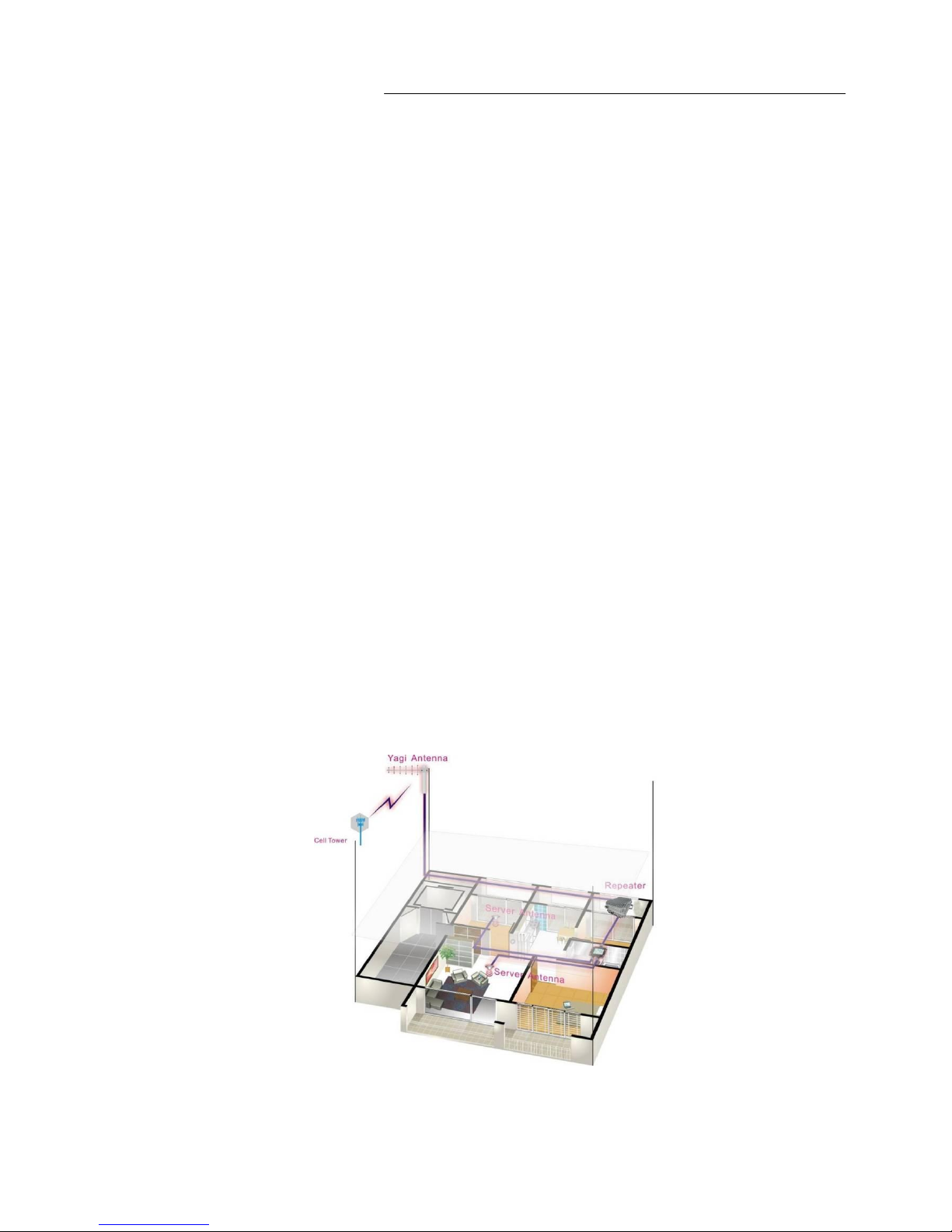
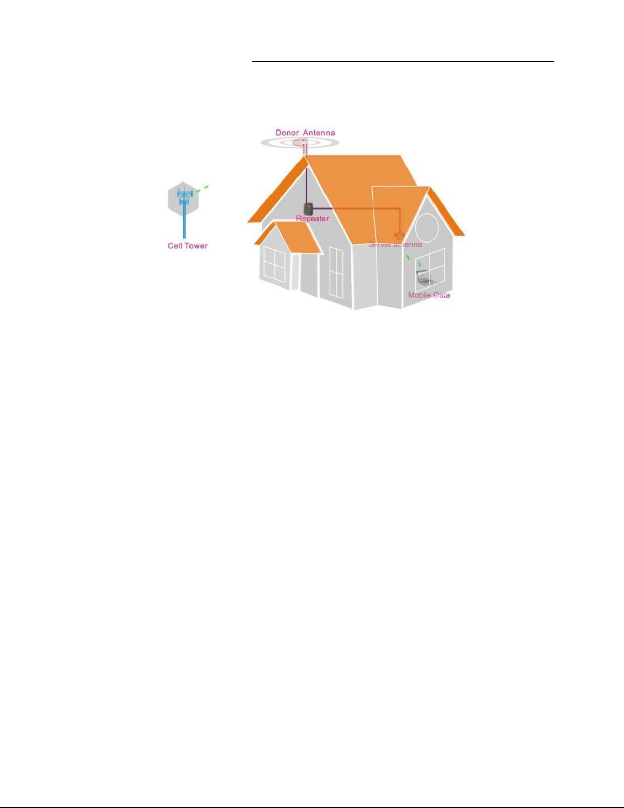
Below diagram shows how simple and fast digital repeater system is installed and works effectively.
One donor antenna, has been installed at the top of the roof to pick up good mobile signals from outside, and
send through a 5D-FB cable to a digital repeater to be amplified significantly, then the output signals are divided
into two signals by a 2way splitter, sent to two indoor omni antennas and finally transmitted into the coverage
area. Very clear phone call or high speed mobile data services are immediately affected within the area.
Digital Repeater User Manual
- 7 -
4 System Characteristics
4.1 Features
Excellent out of band rejection
Wide power supply range and low power consumption
High-integration (One board to contain low-noise amplifier, frequency selection module, power
amplifier module)
Manual gain control provides a variety of applications
Support multi-system, multi-band, band selectable and adjustable
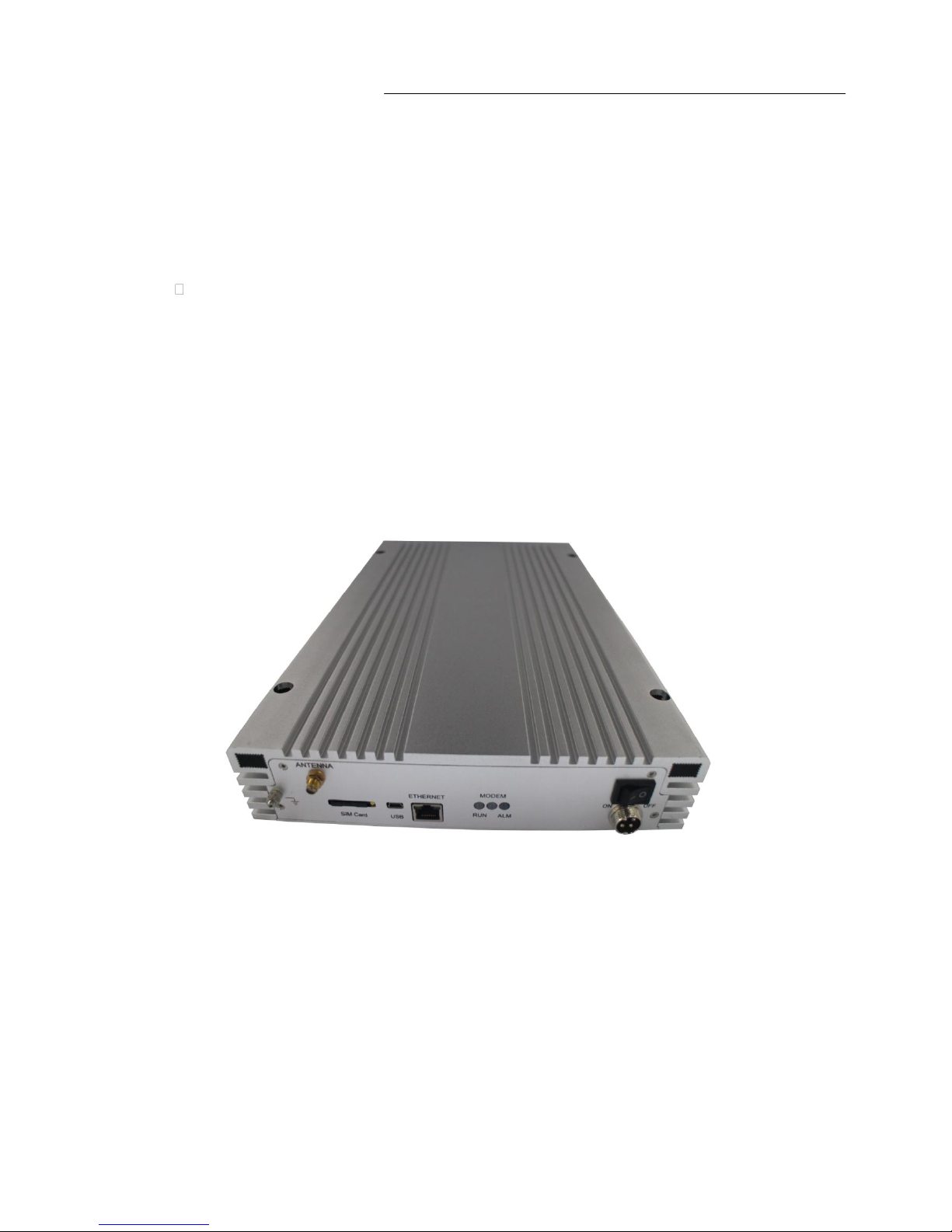
4.2 Appearance of DIGITAL repeaters
Figure 1 the front view (colors may differ from real products).
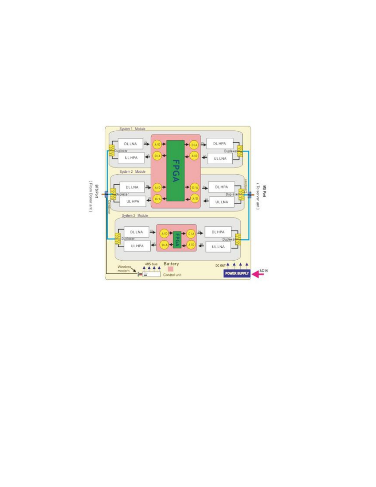
5 Block diagram and work principle
Digital repeater is basically a bi-directional amplifier, the downlink signals are received by the repeater from
BTS by the donor antenna, filtered by its internal duplexers and FPGA module, amplified by low noise amplifier
Digital Repeater User Manual
- 8 -
(LNA) and downlink PA unit, and then sent via the server antenna to the coverage area. The bandwidth is
operators’ working frequency only.
The uplink signal of mobile terminal from the coverage area is input via the server antenna, then filtered by
duplexers and FPGA module, amplified by the uplink low noise amplifier (LNA) and the uplink PA unit and finally
sent via the donor antenna to the BTS.
Modules in the system diagram:
Combiner:The main purpose of combiner is to combine two system to share the same antennas.
Duplexer: The main purpose of duplexer is to combine downlink and uplink to share the same
antennas, the duplexer is composted of one pair of band pass filter that can not only reject the
spurious interference, but also increase the isolation of Uplink and Downlink.
LNA: LNA is the first active sub system of the repeater, of which low noise and high linearity is
requested under strong input signals. LNA is the major sub system that determines the noise figure
of the repeater system.
FPGA: Field-Programmable Gate Array, FPGA module is to process the digital signal transferred
from analog signal and filter the signal out of selective band.
PA: The power amplifier sub system helps the repeater to reach its targeted output power, linearity
of which decides the linearity of the repeater.
Power supply is to supply power electricity to all repeaters’ modules.
Digital Repeater User Manual
- 9 -
6 The repeater system
Donor Antenna:
5~7dbi outdoor panel or 7~9dBi wide band Yagi are recommended as donor antenna.
Function: Pick up donor signals from the BTS and send to the repeater by cable; the received
signals’ power level and quality influence a lot on the coverage effect. Donor antenna also
transmits the uplink signals from the repeater to BTS.
Server Antenna:
2~3dBi indoor omni ceiling or 5~7dBi indoor panel are recommended.
Omni antenna (Indoor ceiling omni antenna or whip antenna), suitable to installed in the center
and radiate all direction; It is better to use a directional panel antenna or Yagi when the coverage
shape is long and narrow (corridors, long row of houses in two sides, tunnels or elevators or rural
open space).
Cables: LMR 300 or 400, 5D or 8D –FB coax cables are recommended.
Splitters or couplers: when the building structure is too complicated or there is big loss due to thick
walls, etc., splitters or couplers shall be used so that more antennas can be installed in more areas
to distribute the signals to each corner of the coverage area.
Power Box including electricity meter, air switch and groundings, some sites might need surge
arrestors.
7 Installation
Digital repeater should be used to cover the area indoor and the humidity and temperature of working can affect the
reliability of repeater. So, temperature, humidity, dust, interference, power, space requirements and other factors
should be considered during installation of repeater.
 Loading...