

Spotwave SpotCell 141, SpotCell 142 Quick Installation Manual
™
SpotCell 141/142 Quick Installation Guide
www.spotwave.com
Spotwave Wireless Inc. 1 Hines Road, Ottawa ON K2K 3C7 Canada
780-00018-01-03
© 2004 Spotwave Wireless Inc. All rights reserved. Printed in Canada
Spotwave and SpotCell are trademarks of Spotwave Wireless Inc. Patents pending.
If required, more detailed information on installing a SpotCell
system can be found in the User Manual which is available for
downloading at
http://www.spotwave.com/support/documentation.
®
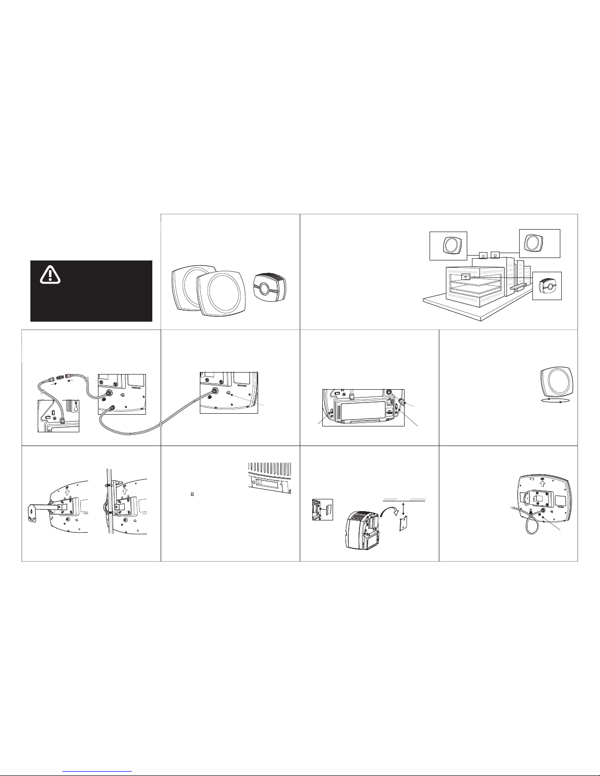
To install the SpotCell system:
®
To install the SpotCell system:
For your safety, beware of power lines and ensure that
appropriate safety measures are maintained at all
times during the installat ion of you r SpotCell
equipment. Contact with high-voltage power lines
could result in death or serious injury.
,
WARNING
2. Location
The DUs can be mounted anywhere your cell
phone works. This may be on a rooftop (typical
rural set-up), on the side of a building, or inside a
building (typical downtown set-up). The CU will
be mounted inside the building where your cell
phone does not work. The illustration at the right
depicts a typical installation.
s are
s
.
To start the installation, place the DUs and CU in
the general areas where they are to be located.
Do not physically mount them at this time.
If the DU mounted indoors, maximum
separation between the DU and CU, and backto-back positioning will optimize performance
DUs
(outward-facing units)
DU
(Cell)
DU
(PCS)
CU
(indoor unit)
1. Parts List
• Mounting kit
• RG6 Cable x 2
• Donor Unit (DU) x 2
• Coverage Unit (CU)
• Power supply
• RG11 cable
3. Connect CU to PCS DU
Connect a 2 meter RG6 cable to the CU and then (using
the provided adapter) join the other end to the longer RG11
cable. Connect the RG11 cable to the upper connector on
the PCS DU.
Back of PCS DU
Back of Cell DU
Back of CU
Back of CU
4. Connect Cell DU to PCS DU
Set the mode switch, located to the right of the label on
the CU, to 1 (install) and then set the band select switch
(to the left of the label) to 800 MHZ.
Connect the power supply to the CU, and then plug the
adapter into the AC outlet.
DU LED
Mode
Switch
Power
Connector
Band
Select
Switch
5. Set Mode and Band Select switches
Set the CU band select switch on the CU to
1900 MHZ. In the location where the PCS
DU is to be mounted, rotate the 1900 MHZ
PCS DU in a complete circle. The LED on the
back will turn red or green during the rotation.
Again, rotate the DU. When the LED turns green, stop the
rotation. This is the direction the PCS DU must face when
mounted.
6. Align DUs
In the location where the Cellular DU is to be mounted,
rotate the 800 MHZ Cellular DU in a complete circle. The
LED on the back will turn red or green during the rotation.
Again, rotate the DU. When the LED turns
green, stop the rotation. This is the direction
the Cellular DU must face when mounted.
Rotate 360°
Connect the Cellular DU to the lower connector on the
PCS DU with the remaining 2 meter RG6 cable.
NOTE: The PCS DU and Cellular DU must be connected
with the RG6 cable before the system is powered on.
10. Final Checklist
7. Mount DUs
Now mount the two DUs. Typical
installations are pictured below.
Wall Mount Pipe Mount with
Hose Clamps
8. Set CU to Active
Set the mode switch, located to the
right of the label on the CU, to 2
(active) and then hold the CU in the
location to be mounted. The LCD
on the bottom of the CU indicates
coverage ( ) by the number of bars;
more bars indicate better coverage.
NOTE: Information for only one band is displayed by the LCD
and status LED at one time.
An indication of poor coverage or a system alarm may not be a
sign of an improperly functioning system, but may result from the
Band Select switch being set to a band that is not currently
available in the area. If this is the case (and you expect the service
to be activated soon) then the associated DU should be aligned
in the same direction as the DU with active signals available.
C
hx
xx P
In S
ervice
9. Mount CU
Fasten the mounting bracket insert to the back of the CU.
Mount the wall bracket at least 4 inches below the ceiling
(to allow enough room for sliding in the CU) on a wall that
is close to the center of the area requiring coverage. Mount
the CU by sliding the insert into the bracket.
4 inches
ceiling
1. Properly ground the DUs via the
grounding bolts.
2.
s
s
3. Firmly affix the cable to the
building where it runs between
the DU and CU.
If the DU is mounted
outdoors, ensure that there
is a drip loop on the cable
connecting to the DU , on
the cables connecting to
both sides of the ground
block, and where the cable
enters the building.
Ground
bolt
 Loading...