

Page 1

Revision 0.2 STINGR Users Manual
STINGR Users Manual
06/24/15
Revision 0.2 Subject To Change without Notice P a g e | 1
Page 2

Revision 0.2 STINGR Users Manual
Table of Contents
1 Introduction .................................................................................................................................................................... 4
1.1 Purpose ................................................................................................................................................................... 4
1.2 Applicable Documents ............................................................................................................................................ 4
1.3 Description .............................................................................................................................................................. 4
2 Application ...................................................................................................................................................................... 5
2.1 Theory of Operation ................................................................................................................................................ 5
2.2 Block Diagram ......................................................................................................................................................... 8
3 Physical Charactersistics ................................................................................................................................................. 9
4 Reference Design .......................................................................................................................................................... 13
4.1 Schematic .............................................................................................................................................................. 14
4.2 PCB ........................................................................................................................................................................ 15
4.3 BOM ...................................................................................................................................................................... 15
5 Application Programming Interface .............................................................................................................................. 16
5.1 Serial Port .............................................................................................................................................................. 16
5.2 Serial Packet Mode ............................................................................................................................................... 16
5.2.1 Serial Packet Format ..................................................................................................................................... 17
5.2.2 STX3 Legacy Serial Packet Commands .......................................................................................................... 17
5.2.2.1 Send Data (0x00) ....................................................................................................................................... 17
5.2.2.2 Query Electronic Serial Number (ESN) (0x01) ........................................................................................... 18
5.2.2.3 Abort Transmission (0x03) ........................................................................................................................ 18
5.2.2.4 Query Bursts Remaining (0x04) ................................................................................................................ 18
5.2.2.5 Query Firmware Version (0x05) ................................................................................................................ 19
5.2.2.6 Setup (0x06) .............................................................................................................................................. 19
5.2.2.7 Query Setup (0x07) ................................................................................................................................... 20
5.2.2.8 Query Hardware Version (0x09) ............................................................................................................... 21
5.2.3 STINGR Serial Packet Commands .................................................................................................................. 22
5.2.3.1 “Initiate proprietary track” command ...................................................................................................... 22
5.2.3.2 “Update Proprietary Track Data” command ............................................................................................. 23
5.2.3.3 “Cancel Proprietary Track” command ...................................................................................................... 24
5.2.3.4 “Send Redundant Burst with GPS” command .......................................................................................... 25
5.2.4 STINGR Serial Test Commands ...................................................................................................................... 27
06/24/15
Revision 0.2 Subject To Change without Notice P a g e | 2
Page 3

Revision 0.2 STINGR Users Manual
5.3 “Transmitter Test” command ............................................................................................................................... 27
5.4 Example CRC calculation routines for serial packets ............................................................................................ 29
6 Test Modes .................................................................................................................................................................... 31
7 REGULATORY APPROVAL .............................................................................................................................................. 33
7.1 Radio Astronomy Site Avoidance .......................................................................................................................... 33
7.2 Regulatory Notices ................................................................................................................................................ 33
06/24/15
Revision 0.2 Subject To Change without Notice P a g e | 3
Page 4
Revision 0.2 STINGR Users Manual
1 Introduction
1.1 Purpose
This document describes the physical, electrical, and functional characteristics of the STINGR satellite transmitter
module. The information contained in this document is intended to provide the end user with the necessary
technical information required to use the module in a custom application.
This document is intended to be used by engineers and technical management and assumes a general knowledge of
basic engineering practices by the user.
1.2 Applicable Documents
1.3 Description
The STINGR is a simplex Satellite transmitter designed to send small packets of user defined data to a network of
low earth orbiting (LEO) satellites using the Globalstar simplex satellite network. The received data is then
forwarded to a user defined network interface that may be in the form of an FTP host or HTTP host where the user
will interpret the data for further processing.
The STINGR is a satellite transmitter radio module which contains a satellite transmitter, GPS receiver, motion
sensor, and a dual band patch antenna. The STINGR is a surface mount module designed to attach to a user defined
host PCB which must provide power and communications with a host processor which will control the operation of
the STINGR. All electrical connections are provided via the castellated pads on the perimeter of the PCB.
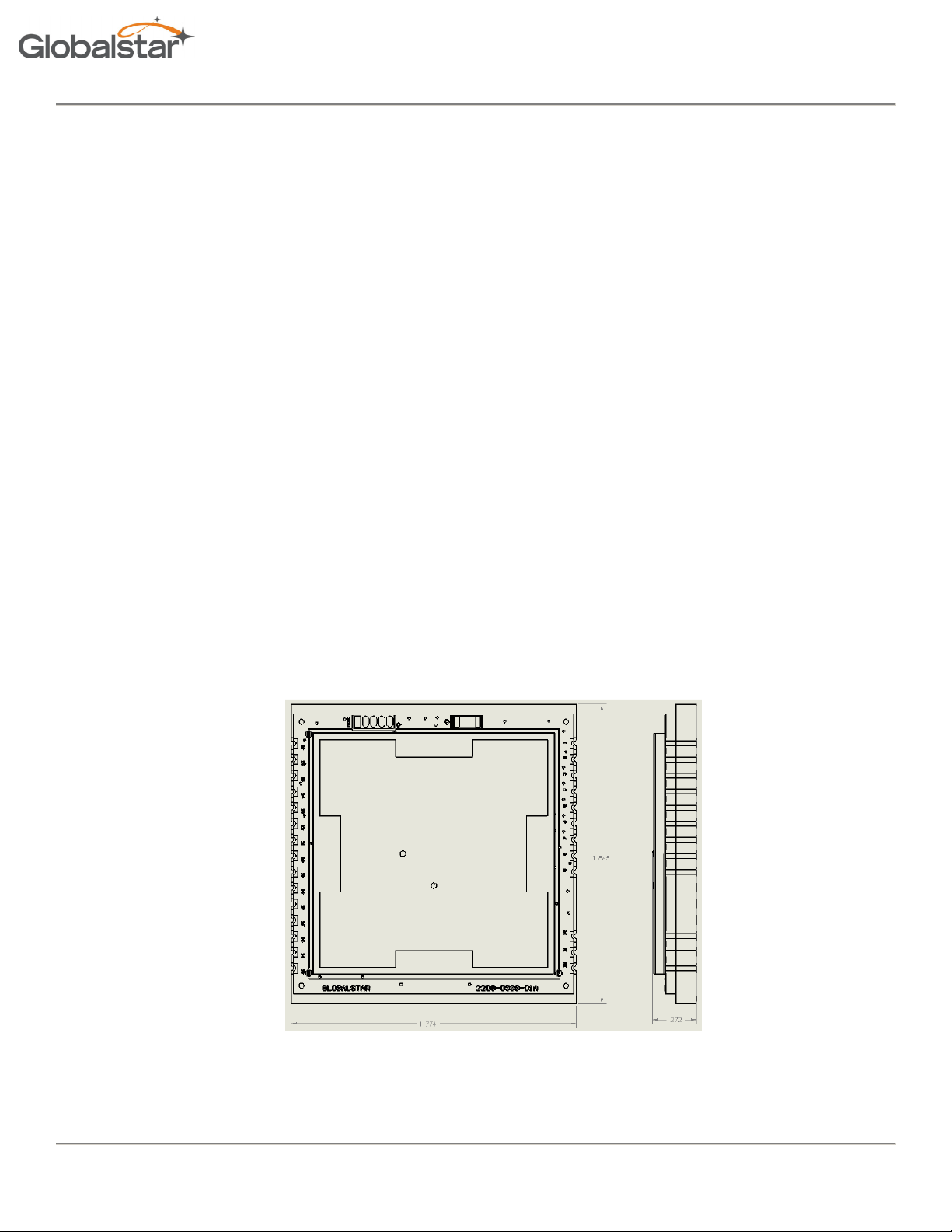
The STINGR is a small, low-profile device with the dimensions shown below.
06/24/15
Figure 1 (dimensions in inches)
Revision 0.2 Subject To Change without Notice P a g e | 4
Page 5

Revision 0.2
Subject To Change without Notice
operates on the Globalstar LEO satellite network. LEO (Low Earth Orbit) means that there are a number of
tly orbit the planet and can communicate with Globalstar devices that are within
Since the satellite position is constantly changing, simplex devices on the ground will
the transmission
gateway as shown below. Once received by the
simplex gateway where redundant messages are discarded and the data from the
message is sent to the OEM via the Internet.
P a g e
transmit (with no knowledge of
may be received by one or more satellites. These satellites will then
satellite
2 Application
2.1 Theory of Operation
The STINGR
satellites in low earth orbit that constan
range of its current position.
STINGR Users Manual
any of the satellites locations) and
relay the message to the nearest satellite
message will be delivered to the
Figure 2 LEO Constellation
gateway, the simplex
06/24/15
Revision 0.2
| 5
Page 6
Revision 0.2
Subject To Change without Notice
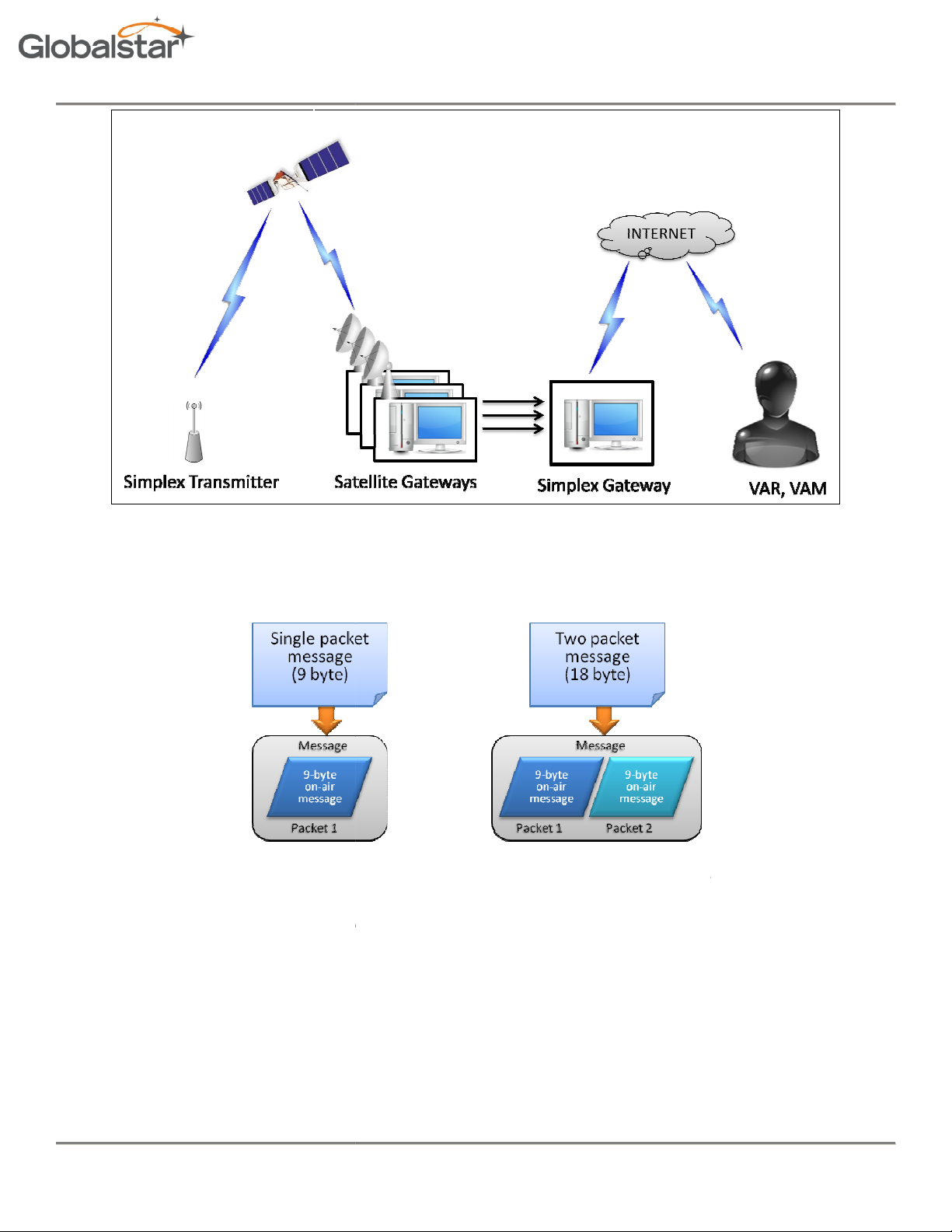
byte payloads. The
payloads greater than 9 bytes will require multiple on
here there is no satellite in range of the simplex transmitters due to obstructions
satellite coverage geometry. Since a simplex device has no way of knowing if a transmitted message has been
device is designed to
sent over the Globalstar network. The default value for the number of redundant
STINGR
The redundant transmissions
packet message using the default setting of 3 redundant
P a g e
byte on
to be transmitted for each user payload.
multiple (redundant) transmissions
transmissions
ach transmission will contain the exact same
minute
STINGR Users Manual
Messages are composed of 1 or more 9-
There are brief periods of time w
and/or
successfully received, the STINGR
means that each message sent to the
data payload.
Figure 3 Simplex Messaging
STINGR can only transmit 9-
-air packets
send
will be transmitted 3 times. E
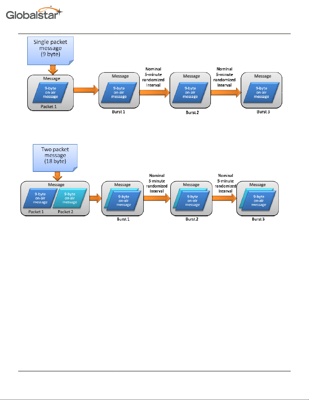
of each message will be sent on a randomized 5-
-air messages, so user
for each message being
per message is 3. This
nominal interval.
The transmission sequence for a singlebelow.
06/24/15
Revision 0.2
transmissions is shown
| 6
Page 7
Revision 0.2
Subject To Change without Notice
packet message using the default setting of 3 redundant transmissions is shown
For normal conditions where the transmitter has an open view of the sky, this will result in a bett
P a g e
The transmission sequence for a twobelow.
STINGR Users Manual
that the message will be received.
er than 99% chance
06/24/15
Revision 0.2
| 7
Page 8
Revision 0.2
Subject To Change without Notice
2.2 Block Diagram
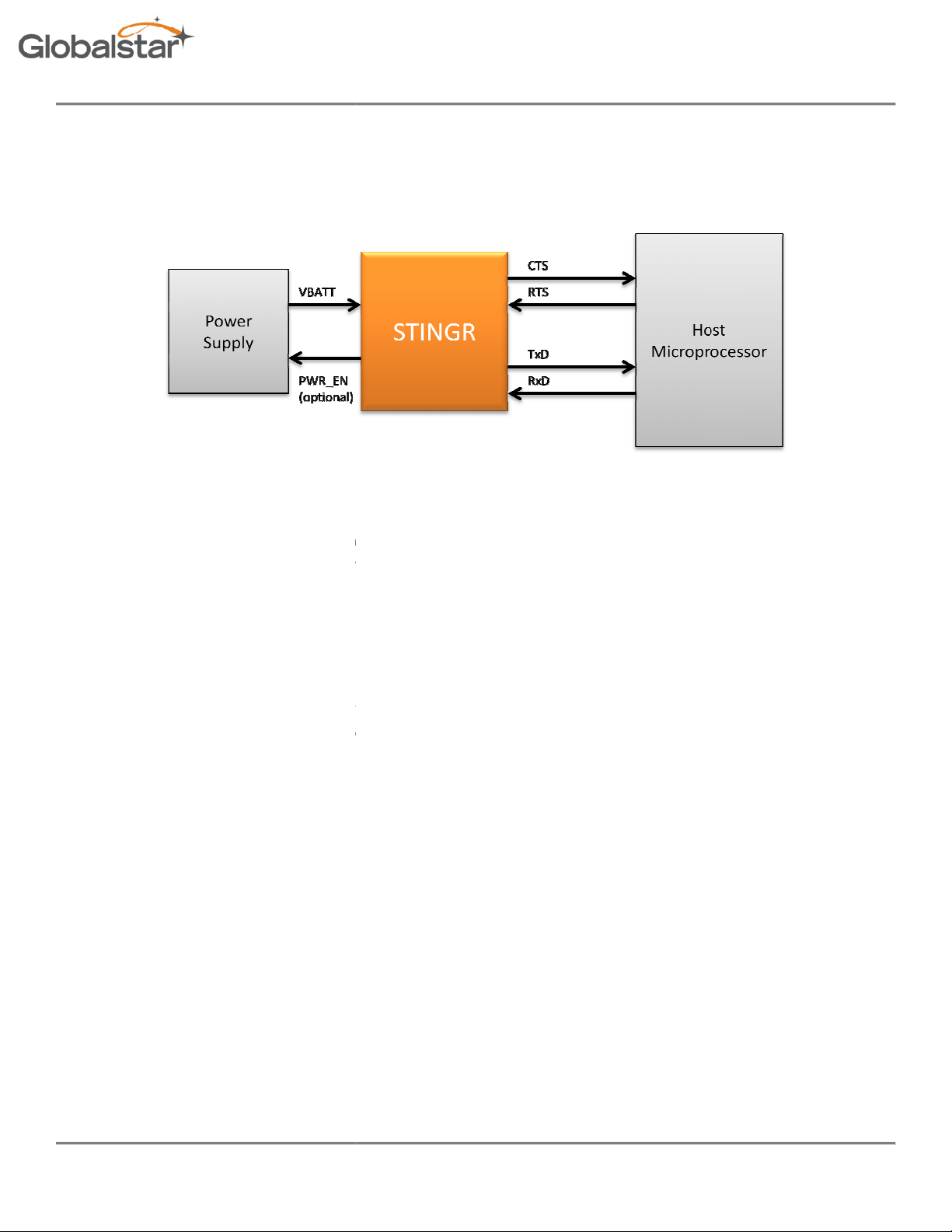
The basic elements of a design utilizing the
power supply input.
required transmit current during RF transmissions.
. This provides the capability to leave the
and the GPS section
is transmitting a data packet.
active transmissions in order to minimize the power consumption of the STINGR.
be turned off the majority of the time and only active during the transmission of a pa
to the random nature of the burst transmissions, and open collector output (PWR_EN) is provided by the
high current supply for
This will ensure that the RF power supply
amount of time to complete each transmission. It may also be monitored by the host to determine when each
burst has been completed without the need to
P a g e
current battery which can provide the
The STINGR has internal regulators which provide separate power
in a low power consumption state
RF power supply is a high power
supply off except during
Since the transmission duty cycle is
VBATT can NOT be turned off between bursts when
high current mode
STINGR Users Manual
STINGR simplex transmitter are shown below.
Figure 4
The STINGR provides a single
for the digital, RF and GPS circuitry
when the transmitter RF section
is only required while the STINGR
very low, this supply will
can directly control an external
sending a multi-packet message).
minimum
Normally, this will be a high-
STINGR
is idle. The internal
Internal cirucuitry turns this
VBATT (
query the STINGR via the serial host interface.
supply which
cket. Due
STINGR which
is enabled for the
06/24/15
Revision 0.2
| 8
Page 9
Revision 0.2 STINGR Users Manual
3 Physical Charactersistics
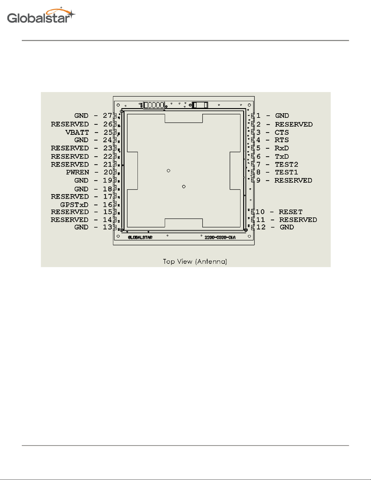
Figure 5 Top View
06/24/15
Revision 0.2 Subject To Change without Notice P a g e | 9
Page 10
Revision 0.2 STINGR Users Manual
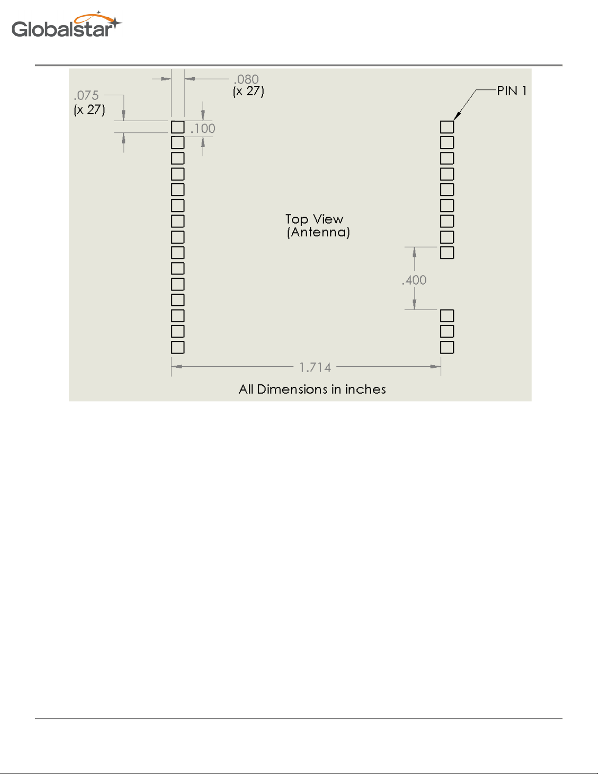
Figure 6 Recommended PCB footprint layout
06/24/15
Revision 0.2 Subject To Change without Notice P a g e | 10
Page 11

Revision 0.2 STINGR Users Manual
PIN NAME
TYPE
Description
1 GND
Ground
2 RESERVED
RESERV
ED Do NOT connect
3 CTS Output
3.0V Open Collector
, weak internal pull
-
up, may be pulled up to 5V max external
4 RTS Input
3.0V (
5V tolerant
)
, weak internal pull
-up
5 RxD Input
3.0V (
5V tolerant
)
, weak internal pull
-up
6 TxD Output
3.0V Open Collector
, weak internal pull
-
up, may be pulled up to 5V max external
7 Test2
Input
8 Test1
Input
9 RESERVED
RESERVED
Do NOT connect
10 RESET
Input
Only drive with open collector, no external voltage to be applied
11 RESERVED
RESERVED
Do NOT connect
12 GND
Ground
13 GND
Ground
14 RESERVED
RESERVED
Do NOT connect
15 RESERVED
RESERVE
D Do NOT connect
16 GPS
TxD Output
5V tolerant, weak internal pull
-
up, may be pulled up to 5V max external
17 RESERVED
RESERVED
Do NOT connect
18 GND
Ground
19 GND
Ground
20 PWR_EN
Output
Open collector output to control VRF supply
21 RESERVED
RESER
VED Do NOT connect
22 RESERVED
RESERVED
Do NOT connect
23 RESERVED
RESERVED
Do NOT connect
24 GND
Ground
25 VBATT
Power In
3.0 to 5.
5 Volts
, 400 mA max load @ 3.7V
26 RESERVED
RESERVED
Do NOT connect
27 GND
Ground
Sleep Mode
VBATT is applied, no transmissions are pending, no serial activity
Active Mode
The STINGR is active and responding to the serial port but is not transmitting
Standby Mode
The STINGR is inactive between transmissions but is not transmitting
Internal pull-up, ground or use open collector output, no external voltage to be applied
Internal pull-up, ground or use open collector output, no external voltage to be applied
Operating Temperature Range -40 to +85°C
VBATT Power Supply Operational Range 3.0 to 5.5 Volts
ABSOLUTE MAXIMUM RATINGS
VBATT 6.0 Volts
Voltage onTxD,RxD,RTS,CTS 5.0 Volts
Operating Modes
06/24/15
Revision 0.2 Subject To Change without Notice P a g e | 11
Page 12

Revision 0.2 STINGR Users Manual
Transmit Mode
The unit is transmitting an RF packet
Parameter
Test Conditions
Min Typ Max
Unit
Transmit mode supply current
-40-85º C, V
BATT
=3.7
volts
425 450 500 mA
Active mode supply current
25º C, V
BATT
= 3.7
volts
2.3 2.5 mA
Standby mode supply current
25º C,
VBATT
= 3.7
volts
12 50 uA
Sleep mode supply current
25º C, Vcc = 3.
7 volts
8 40 uA
06/24/15
Revision 0.2 Subject To Change without Notice P a g e | 12
Page 13

Revision 0.2 STINGR Users Manual
4 Reference Design
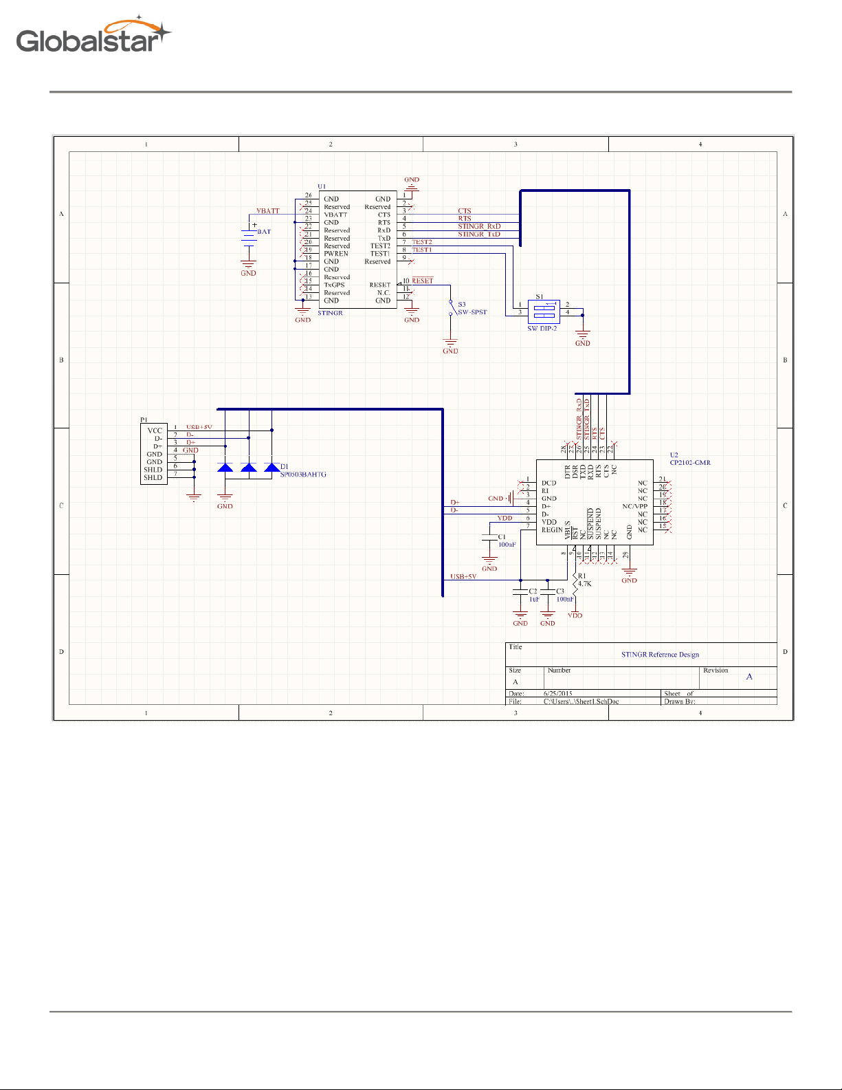
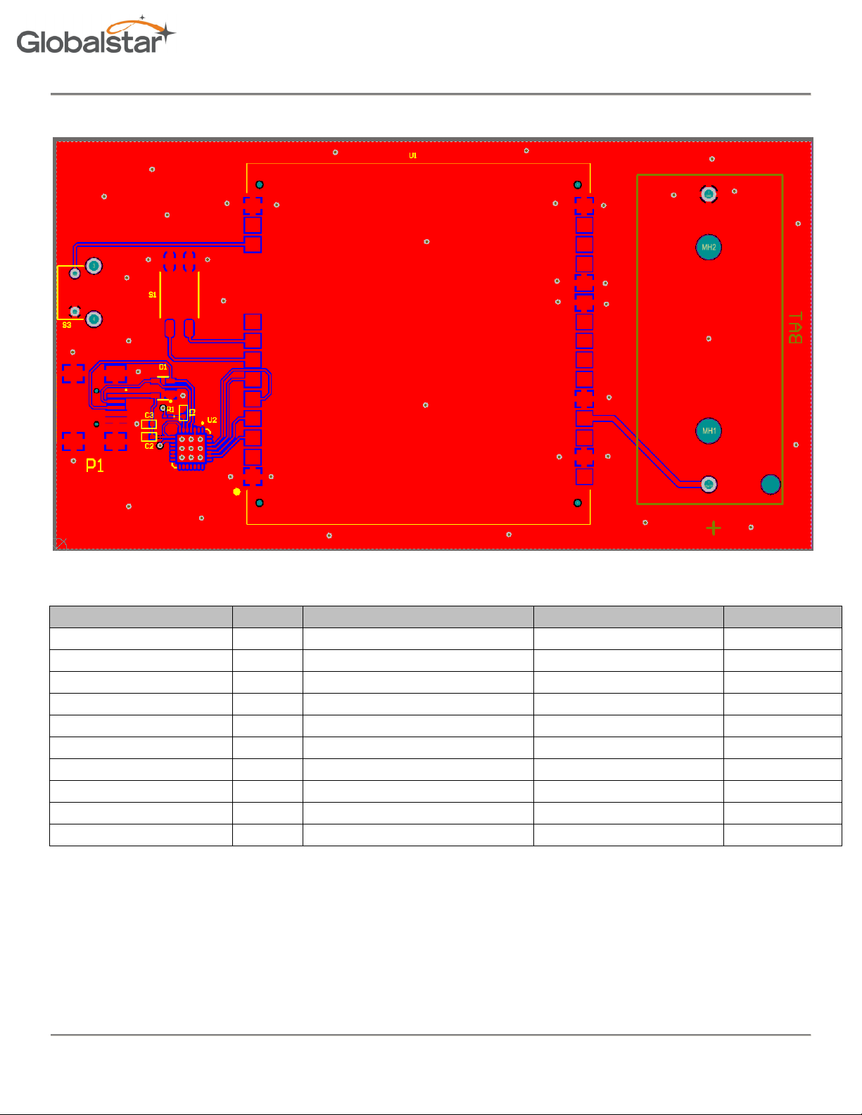
The reference design presented below illustrates a basic implementation using the STINGR module in conjunction with a
primary battery, USB interface, and test mode switches.
Since the battery is located on the same board as the STINGR, no decoupling capacitor is required on the VBATT input,
however, if there are battery leads, lengthy power distribution, or noise sources present, a suitable decoupling capacitor
might be appropriate. A ceramic XR7 10uF capacitor is usually a good choice.
Switch S1 can be used to initate test modes of operation without using the USB serial interface using the settings shown
in Table 6.1. Select the desired test mode and depress S3 (reset) to execute the selected test mode.
When interfacing to a host processor, replace the USB serial interface with a 3.0 volt serial interface.
The USB interface is powered by the USB bus, however, due to the high peak current requirements of the STINGR during
transmissions, the STINGR is powered by the battery.
06/24/15
Revision 0.2 Subject To Change without Notice P a g e | 13
Page 14
4.1 Schematic
Revision 0.2 STINGR Users Manual
06/24/15
Revision 0.2 Subject To Change without Notice P a g e | 14
Page 15
4.2 PCB
Revision 0.2 STINGR Users Manual
4.3 BOM
Manufacturer Part Number Designator Description Manufacturer Quantity
BC2/3AE BAT Multicell Battery MPD 1
GRM155R71A104KA01D C1, C3 CAP 0402 CER 100NF 10V X7R +/-10% MURATAELEC 2
04026D105KAT2A C2 CAP 0402 CER 100NF 10V X7R +/-10% AVXCORP 1
SP0503BAHTG D1 3 channel ESD protection diode array Little Fuse 1
897-43-005-00-100001 P1 CONN HDR USB-MINI-D Mill-Max 1
ERJ-2GEJ104X R1 RES 0402 TKF 100K 5% 1/16W Panasonic Electronic Components 1
KAJ02LGGT S1 DIP Switch, 2 Position, SPST E-Switch 1
MJTP1117 S3 Single-Pole, Single-Throw Switch Apem Inc. 1
2350-0339-01 U1 STINGR Globalstar, Inc. 1
CP2102-GMR U2 USB-Serial Interface Silicon Labs 1
06/24/15
Revision 0.2 Subject To Change without Notice P a g e | 15
Page 16
Revision 0.2 STINGR Users Manual
5 Application Programming Interface
5.1 Serial Port
A half-duplex (0-3.0V) TTL asynchronous serial port (UART) is the primary interface to the user equipment. The serial
port operates with the serial parameters of 9600bps, 8 data bits, no parity, 1 stop bit.
The RX data input and the RTS inputs are 5V tolerant. The TX data and CTS outputs are 0-3.0V TTL.
RS232 input levels are not supported. RS232 data must be converted to TTL before being sent to the unit.
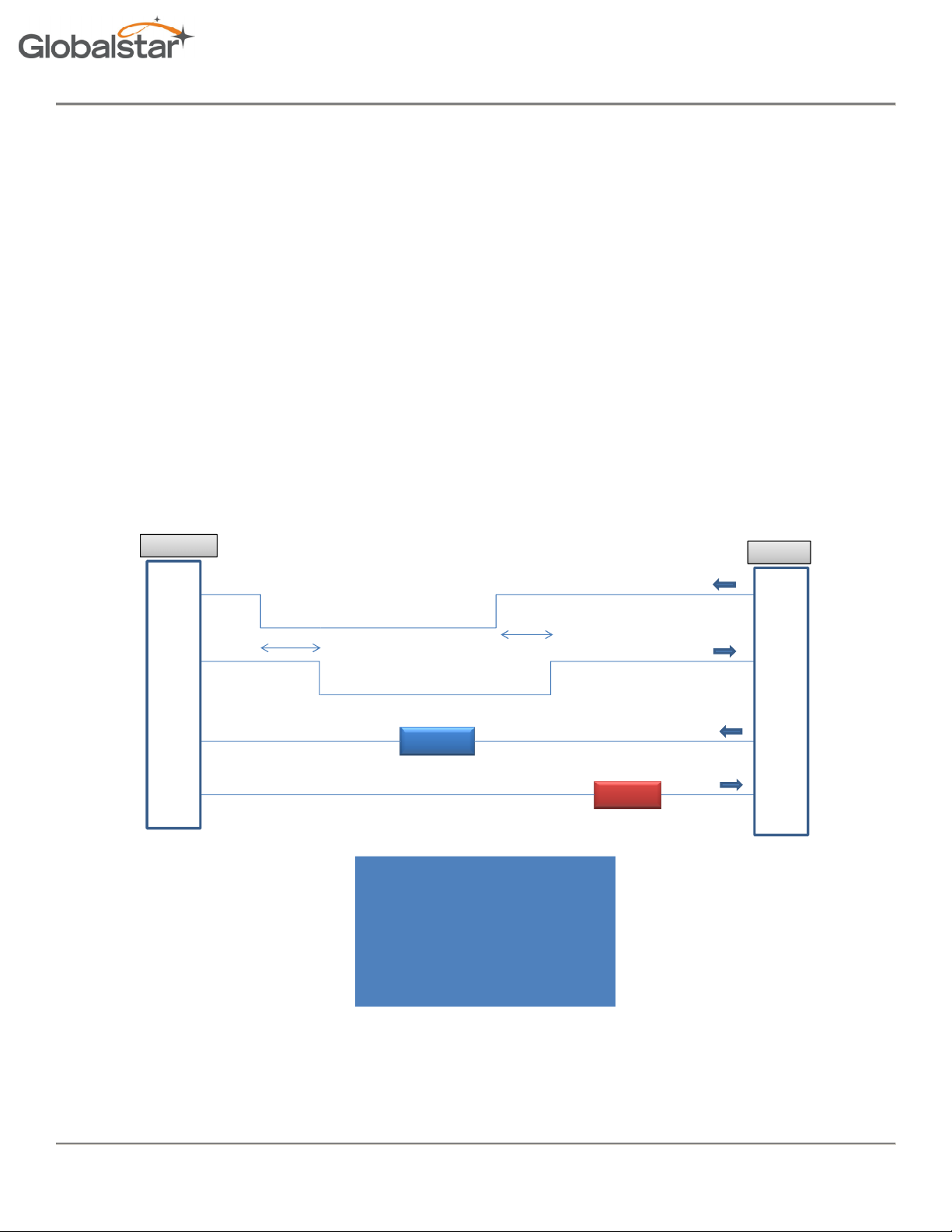
Each command from the DTE to the STINGR is sent in a serial packet. Upon receiving the command, the modem answers
to the DTE and, if applicable, executes the command.
In order to wake the STINGR from sleep mode and to indicate the end of the serial packet, each serial packet must be
framed by activating RTS before the first byte of the command and deactivating RTS after the last byte of the command.
STINGR pins
RTS
CTS
RxD
TxD
< 125 ms
< 25 ms
Command
1. Lower RTS
2. Wait for CTS to go low
3. Send Command to STINGR
4. Raise RTS
5. STINGR raises CTS
6. STINGR sends response
Response
Host pins
TxD
RxD
5.2 Serial Packet Mode
This mode is the legacy mode of operation as implemented in the STX2 and STX3 which consists of binary data packets.
06/24/15
Revision 0.2 Subject To Change without Notice P a g e | 16
Page 17
Revision 0.2
Subject To Change without Notice
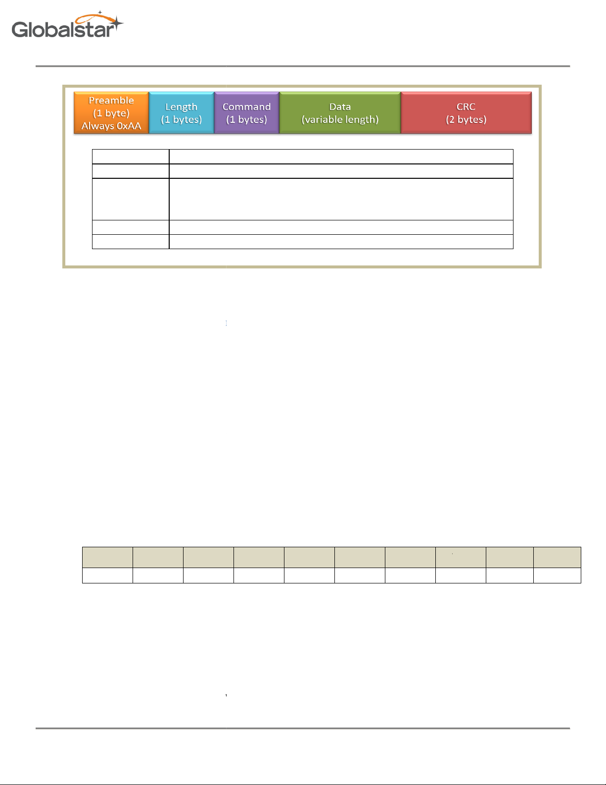
Fixed pattern 0xAA
Total number of bytes in the serial packet including the preamble
Command type (See Table 5 Serial Packet Type). Responses to
commands carry the same command type as the command that
initiated the answer
Data associated with the command or answer
16 bit CRC
Serial Packet Commands
as described below:
byte
byte
operly formatted command is received, the
STINGR
01 02 03 04 05 06 07 08 09
receives a properly formatted Send Data command, it returns an acknowledge response as shown above. If
the command is not properly formatted, it will return the NAK response
P a g e
will return a NAK response:
to send from 1 to 144 data bytes over the Globalstar Simplex network.
pa
yload
payload
payload
payload
he Globalstar Simplex network.
5.2.1 Serial Packet Format
STINGR Users Manual
Preamble
Length
Command
Data
CRC
5.2.2 STX3 Legacy
For all serial packet commands
• AA is the Preamble.
• NN is the Length.
• XX is an unspecified byte value
• CLSB is the least significant CRC
• CMSB is the most significant CRC
• If an impr
Figure 7 Serial Packet Format
STINGR
AA 05 FF A1 CB
5.2.2.1 Send Data (0x00)
The Send Data command requests the
0x00
Leader Len cmd
AA NN 00
Example Command: AA 0E 00
Response: AA 05 00 D9 C4
The example above commands the STINGR
the STINGR
06/24/15
Revision 0.2
1
XX XX XX XX
to send 9 bytes of user defined data over t
2
BE E8
3 ..
AA 05 FF A1 CB.
N CRC1 CRC2
XX
CLSB CMSB
If
| 17
Page 18
Revision 0.2 STINGR Users Manual
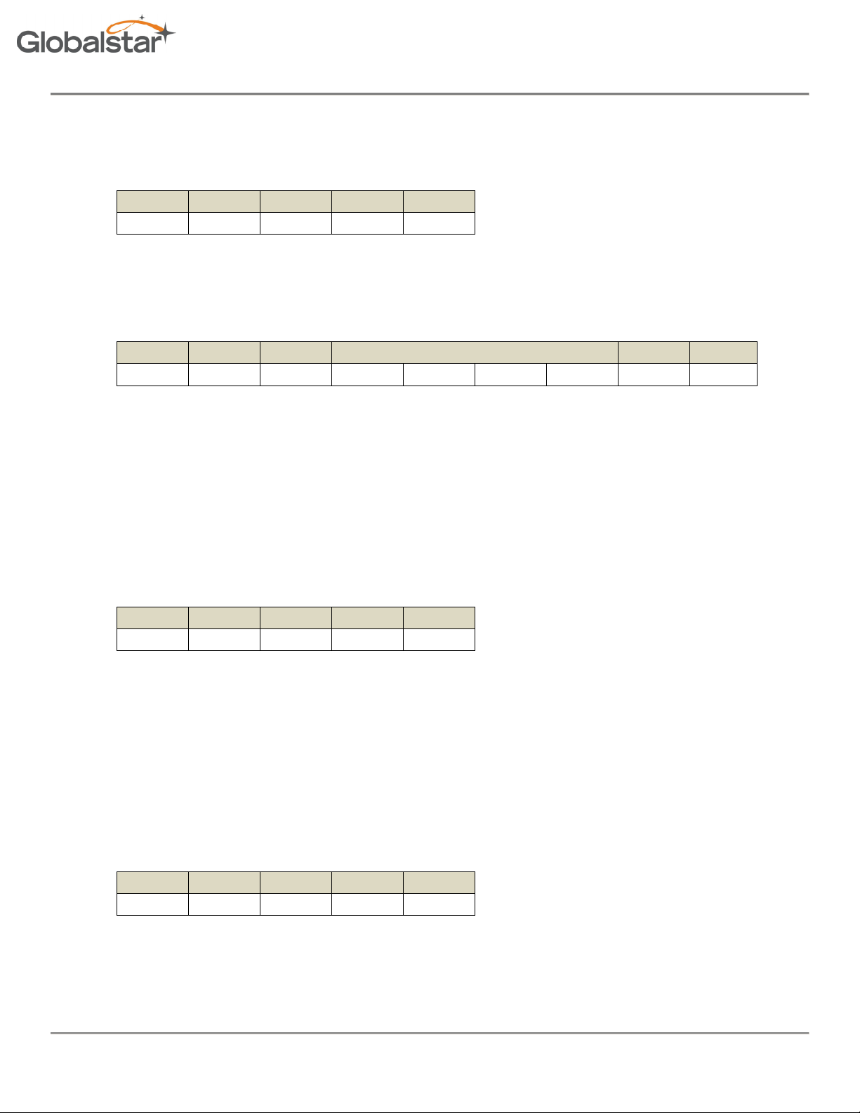
5.2.2.2 Query Electronic Serial Number (ESN) (0x01)
The Electronic Serial Number command requests the STINGR to respond with the units Electronic Serial Number (ESN).
0x01
Leader Len Cmd CRC1 CRC2
AA 05 01 50 D5
Command: AA 05 01 50 D5
Response:
Leader len Cmd ESN CRC1 CRC2
AA 09 01 XX XX XX XX
Example Response: AA 09 01 00 23 18 60 86 7A
Where the ESN returned is 2300000.
86 7A
5.2.2.3 Abort Transmission (0x03)
The Abort Transmission command requests the STINGR to abort the current message transmit sequence over the
Globalstar Simplex network.
0x03
Leader len Cmd CRC1 CRC2
AA 05 03 42 F6
Command: AA 05 03 42 F6
Response: AA 05 03 42 F6
5.2.2.4 Query Bursts Remaining (0x04)
The Query Bursts Remaining command requests the STINGR to return the current number of bursts remaining the
current message transmit sequence over the Globalstar Simplex network.
0x04
Leader len cmd CRC1 CRC2
AA 05 04 FD 82
Command: AA 06 04 00 F4 33
06/24/15
Revision 0.2 Subject To Change without Notice P a g e | 18
Page 19
Revision 0.2 STINGR Users Manual
Response:
Leader Len 04 count CRC1 CRC2
AA 05 04
Example Response: AA 06 04 00 F4 33
Where the bursts remaining returned is: 0
5.2.2.5 Query Firmware Version (0x05)
The Query Firmware Version command requests the STINGR to return the current firmware version.
0x05
Leader Len cmd CRC1 CRC2
AA 05 05 74 93
Command: AA 05 05 74 93
XX
CC CC
Response:
Leader Len 4 FW major FW minor CRC1 CRC2
AA 7 5
XX XX
CC CC
Example Response: AA 07 05 01 07 E0 6A
Where the firmware version returned is: 1.7
5.2.2.6 Setup (0x06)
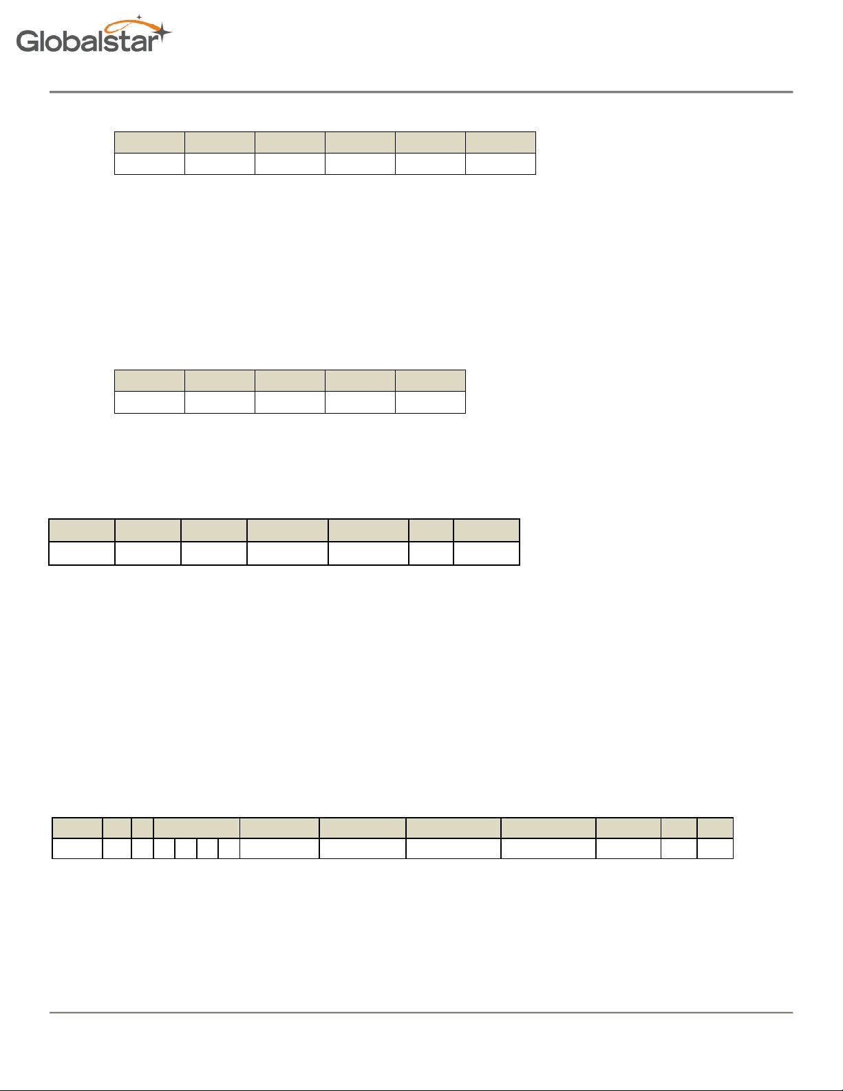
The Setup command requests the STINGR to use the specified current setup parameters. These are stored in nonvolatile memory.
0x06
Command:
header len 04 RF channel # of Bursts Interval Min Interval Max RESERVED CRC1 CRC2
AA 0E 06 XX XX XX XX
RESERVED
XX XX XX XX
XX CC CC
06/24/15
Revision 0.2 Subject To Change without Notice P a g e | 19
Page 20
Revision 0.2 STINGR Users Manual
RF
# of
Interval
Interval
Where:
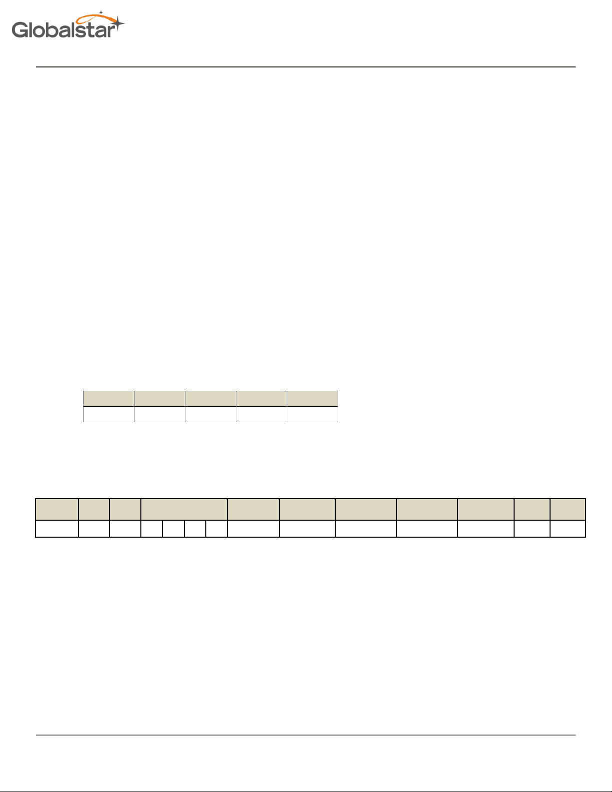
• RF channel : Valid values are: 0 = Channel A, 1 = Channel B, 2 = Channel C, 3 = Channel D
• # of bursts: Valid values are: 0x01 thru x14 (1 to 20 bursts)
• Minimum Burst Interval: Units of 5 seconds. Valid values are: 0x01 thru 0x3C (5 to 300 seconds)
• Maximum Burst Interval: Units of 5 seconds. Valid values are: 0x02 thru 0x78 (10 to 600 seconds)
Example Command: AA 0E 06 00 00 00 00 00 03 18 30 00 CE 9C
Where the setup information is:
• RF channel : 00 Channel A
• # of bursts: 03 3 bursts per message
• Minimum Burst Interval: 18 0x18 = 24, 24 x 5 = 120 seconds
• Maximum Burst Interval: 30 0x30 = 48, 48 x 5 = 240 seconds
5.2.2.7 Query Setup (0x07)
The Query Setup command requests the STINGR to return the current setup parameters.
0x07
Leader len cmd CRC1 CRC2
AA 05 07 66 B0
Command: AA 05 07 66 B0
Response:
Leader len cmd RESERVED
AA 0E 07 XX XX XX XX
channel
XX XX XX XX
Bursts
Min
Max RESERVED CRC1 CRC2
XX 18 59
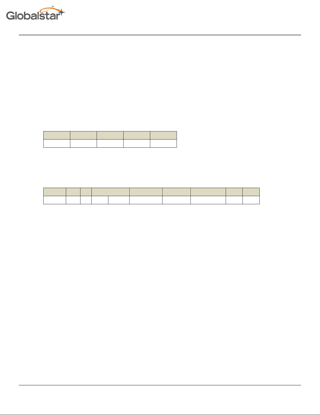
Where:
• RF channel : Valid values are: 0 = Channel A, 1 = Channel B, 2 = Channel C, 3 = Channel D
• # of bursts: Valid values are: 0x01 thru x14 (1 to 20 bursts)
• Minimum Burst Interval: Units of 5 seconds. Valid values are: 0x01 thru 0x3C (5 to 300 seconds)
• Maximum Burst Interval: Units of 5 seconds. Valid values are: 0x02 thru 0x78 (10 to 600 seconds)
Example Response: AA 0E 07 00 23 18 60 00 03 18 30 00 5D 60
06/24/15
Revision 0.2 Subject To Change without Notice P a g e | 20
Page 21
Revision 0.2 STINGR Users Manual
01
Where the setup information returned is:
• RF channel : 00 Channel A
• # of bursts: 03 3 bursts per message
• Minimum Burst Interval: 18 0x18 = 24, 24 x 5 = 120 seconds
• Maximum Burst Interval: 30 0x30 = 48, 48 x 5 = 240 seconds
5.2.2.8 Query Hardware Version (0x09)
The Query Hardware Version command requests the STINGR to return the current hardware version information.
0x09
Leader len Cmd CRC1 CRC2
AA 05 09 18 59
Command: AA 05 09 18 59
Response:
Leader len 04 Device Code Board Rev CPU Rev Radio Rev CRC1 CRC2
AA 0A 09 00
XX XX XX
Where:
• Device Code : Always 1 for STINGR
• Board Revision: STINGR hardware revision
• CPU Revision: STINGR CPU revision
• Radio Revision: STINGR radio revision
Example Response: AA 0A 09 00 01 00 8E 62 E5 5E
Where the revision information returned is:
• Board Revision: 00
• CPU Revision: 8E
• Radio Revision: 62
CC CC
06/24/15
Revision 0.2 Subject To Change without Notice P a g e | 21
Page 22

Revision 0.2 STINGR Users Manual
Byte
Bits Parameter
Description
in minutes between the track points.
Interval
Interval
5.2.3 STINGR Serial Packet Commands
5.2.3.1 “Initiate proprietary track” command
This command allows the initiation of a periodic track with user defined data prepended and appended to the latitude
and longitude fields. A periodic 9 byte custom track message, transmitted nominally at the interval specified, will result.
Initiate proprietary track command format
0 0 – 7 Leader
1 0 – 7 Length
2 0 – 7 Command Code.
3 -4 0 - 15 Interval Interval
5 0 - 7 Byte 0 value
6 0 - 7 Byte 7 value
7 0 - 7 Byte 8 value
8-9 0 - 15 CRC
Leader len Cmd
AA 0A 30 00 05 AA BB CC 18 59
(MSB)
(LSB) Byte 0 Byte 7 Byte 8 CRC1 CRC2
Example Command: AA 0A 30 00 05 AA BB CC 69 36
Always a value of 0xAA.
0x0A (decimal 10)
0x30 = Initiate proprietary track.
MIN and MAX allowed TBD.
The value to transmit as byte 0
The value to transmit as byte 7.
The value to transmit as byte 8.
Where:
• Period : 0x0005 (5 minute intervals)
• Payload Byte 0: 0xAA
• Payload Byte 7: 0xBB
• Payload Byte 8: 0xCC
06/24/15
Revision 0.2 Subject To Change without Notice P a g e | 22
Page 23

Revision 0.2 STINGR Users Manual
Byte
Bits
Parameter
Description
Byte
Bits Parameter
Description
Initiate proprietary track response
0 0 - 7 Leader
1 0 - 7 Length
2 0 - 7 Command Code.
3 -4 0 - 15 CRC
Always a value of 0xAA.
5
0x30 = ACK or 0xFF = NAK
Example Response:
AA 05 30 5A F5
5.2.3.2 “Update Proprietary Track Data” command
This command is used to change the user programmable data in a proprietary track message. If a proprietary track
session is not in progress, it is ACK’d but will do nothing.
Update proprietary track data command format
0 0 – 7 Leader
1 0 – 7 Length
2 0 – 7 Command Code.
3 0 – 7 Byte 0 value
4 0 – 7 Byte 7 value
5 0 – 7 Byte 8 value
6-7 0 – 15 CRC
Leader Len Cmd Byte 0 Byte 7 Byte 8 CRC1 CRC2
AA 08 31
Example Command: AA 08 31 BB CC DD AC 99
Always a value of 0xAA.
0x08
0x31 = Update proprietary track.
The value to transmit as byte 0
The value to transmit as byte 7.
The value to transmit as byte 8.
AA BB CC
18 59
06/24/15
Revision 0.2 Subject To Change without Notice P a g e | 23
Page 24

Revision 0.2 STINGR Users Manual
Byte
Bits
Parameter
Description
Byte
Bits Parameter
Description
Where:
• Payload Byte 0: 0xAA
• Payload Byte 7: 0xBB
• Payload Byte 8: 0xCC
Update Proprietary Track Data response
0 0 - 7 Leader
1 0 - 7 Length
2 0 - 7 Command Code.
3 -4 0 - 15 CRC
Always a value of 0xAA.
5
0x31 = ACK or 0xFF = NAK
Example Response:
AA 05 31 D3 E4
5.2.3.3 “Cancel Proprietary Track” command
This command is used to terminate a proprietary track session.
Cancel Proprietary Track command format
0 0 - 7 Leader
Always a value of 0xAA.
Example Command: AA 05 32 48 D6
06/24/15
1 0 - 7 Length
2 0 - 7 Command Code.
3-4 0 - 15 CRC
Leader Len Cmd CRC1 CRC2
AA 05 32 48 D6
0x05
0x32 = cancel proprietary track.
Revision 0.2 Subject To Change without Notice P a g e | 24
Page 25

Revision 0.2 STINGR Users Manual
Byte
Bits
Parameter
Description
Byte
Bits Parameter
Description
Cancel Proprietary Track response
0 0 - 7 Leader
1 0 - 7 Length
2 0 - 7 Command Code.
3 -4 0 - 15 CRC
Always a value of 0xAA.
5
0x32 = ACK or 0xFF = NAK
Example Response:
AA 05 32 48 D6
5.2.3.4 “Send Redundant Burst with GPS” command
This command is used to initiate a redundant bursted message (as setup in STX configuration). Bytes 1 – 6 of the first
packet of the message shall contain latitude and longitude in standard Globalstar 24 bit format.
Send Redundant Burst with GPS command format
0 0 - 7 Leader
1 0 - 7 Length
2 0 - 7 Command Code.
3 0 - 7 Byte 0 value
4 0 - 7 Byte 7 value
5 0 - 7 Byte 8 value
6 - n Additional data
n+1n+2
0 - 15 CRC
Always a value of 0xAA.
Variable 0x08 – 0x90 (144 bytes)
0x33 = Send Redundant Burst with GPS.
The value to transmit as byte 0 of first packet
The value to transmit as byte 7 of first packet
The value to transmit as byte 8 of first packet
Up to 135 additional bytes of data (15 9 byte
packets). Maximum value of n = 141. If this
number is not divisable by 9, the end of the
final packet of the message will be zero
padded.
06/24/15
Revision 0.2 Subject To Change without Notice P a g e | 25
Page 26

Revision 0.2 STINGR Users Manual
Byte
Bits
Parameter
Description
Leader Len Cmd Byte 0 Byte 7 Byte 8 CRC1 CRC2
AA 08 33
Example Command: AA 08 33 AA BB CC 57 C3
Where:
• Payload Byte 0: 0xAA
• Payload Byte 7: 0xBB
• Payload Byte 8: 0xCC
Example Command: AA 11 33 01 02 03 04 05 06 07 08 09 0A 0B 0C 57 C3
Where:
• Payload Byte 0: 0x01
• Payload Byte 7: 0x02
• Payload Byte 8: 0x03
• Payload Byte 9: 0x04
• Payload Byte 10: 0x05
• Payload Byte 11: 0x06
• Payload Byte 12: 0x07
• Payload Byte 13: 0x08
• Payload Byte 14: 0x09
• Payload Byte 15: 0x0A
• Payload Byte 16: 0x0B
• Payload Byte 17: 0x0C
AA BB CC
57 C3
Example Response:
06/24/15
Send Redundant Burst with GPS response
0 0 - 7 Leader
1 0 - 7 Length
2 0 - 7 Command Code.
3 -4 0 - 15 CRC
AA 05 33 C1 C7
Always a value of 0xAA.
5
0x33 = ACK or 0xFF = NAK
Revision 0.2 Subject To Change without Notice P a g e | 26
Page 27

Revision 0.2 STINGR Users Manual
Byte
Bits Parameter
Description
Test
5.2.4 STINGR Serial Test Commands
5.3 “Transmitter Test” command
This command is used to initiate a transmitter test in one of three modes.
Transmitter test command format
0 0 - 7 Leader
1 0 - 7 Length
2 0 - 7 Command Code.
3 0 - 7 Test mode
4 – 5 0 - 15 CRC
Leader Len Cmd
AA 06 FC
Example Command: AA 06 FC 02 2E A2
Where:
Always a value of 0xAA.
0x06
0xFC = Transmitter test.
The following test modes may be selected:
0x01 = CW Mode
0x02 = Transmit single test packet.
0x03 = Mod mode. Transmit a continuous
signal modulated with a bit pattern.
Mode CRC1 CRC2
02
2E A2
06/24/15
• Test Mode: 0x02 = Single Test Packet
Revision 0.2 Subject To Change without Notice P a g e | 27
Page 28

Revision 0.2 STINGR Users Manual
Byte
Bits Paramete
r Description
Table 50: Transmitter test response format.
0 0 - 7 Leader
1 0 - 7 Length
2 0 - 7 ACK or NAK
3 - 4 0 - 15 CRC
Example Response:
AA 05 FC 3A F9
Always a value of 0xAA.
0x05
0xFC for success, 0xFF for incorrectly
formatted command. A value for the test
mode other than 0x01, 0x02, or 0x03 will
generate a NAK.
06/24/15
Revision 0.2 Subject To Change without Notice P a g e | 28
Page 29

Revision 0.2 STINGR Users Manual
5.4 Example CRC calculation routines for serial packets
The following example is written in the C programming language where:
int = 32 bits, short = 16 bits, char = 8 bits
unsigned short crc16_lsb(unsigned char *pData, int length)
{
unsigned char i;
unsigned short data, crc;
crc = 0xFFFF;
if (length == 0)
return 0;
do
{
data = (unsigned int)0x00FF & *pData++;
crc = crc ^ data;
for (i = 8; i > 0; i--)
{
if (crc & 0x0001)
crc = (crc >> 1) ^ 0x8408;
else
crc >>= 1;
}
}while (--length);
crc = ~crc;
return (crc);
}
USAGE: calculate the CRC for a message and update the message CRC
unsigned short crc = crc16_lsb(msg, msg [1]-2);
msg [msg [1]-2] = (unsigned char) (crc&0xFF);
msg [msg [1]-1] = (unsigned char) (crc>>8);
06/24/15
Revision 0.2 Subject To Change without Notice P a g e | 29
Page 30

Revision 0.2 STINGR Users Manual
The following example is written in the Java programming language:
char crc16_lsb(byte pData[], int length)
{
int pData_i = 0;
char s1,s2;
byte i;
char data, crc;
crc = (char) 0xFFFF;
if (length == 0)
return 0;
do
{
data = (char)((char)0x00FF & pData[pData_i++]);
crc = (char)(crc ^ data);
for (i = 8; i > 0; i--)
{
if ((crc & 0x0001) != 0)
crc = (char)((crc >> 1) ^ 0x8408);
else
crc >>= 1;
}
}while (--length != 0);
crc = (char)~crc;
return (crc);
}
USAGE: calculate the CRC for a message and update the message CRC
byte msg[]; int len;
char crc = crc16_lsb(msg,len-2);
msg[len-2] = (byte)((short)crc & (short)0xff);
msg[len-1] = (byte)((short)crc >> 8);
06/24/15
Revision 0.2 Subject To Change without Notice P a g e | 30
Page 31

Revision 0.2 STINGR Users Manual
TEST1
TEST2
Mode
0 0 Mod Mode
(continuous transmission)
-
A test packet is continuous
ly
0 1 Test Packet
-
The test packet shall comply with the Air Interface
1 0 CW mode
-
An un
-
modulated carrier is
continuously
transmitted
.
1 1 Normal Operation
6 Test Modes
The STINGR provides several test modes intended to aid in manufacturing testing and certification testing.
All test modes are activated by grounding selective pins on the STINGR prior to applying power. Once power is applied,
the STINGR will sample the states of the pins and based on the states of the pins, the STINGR will enter the selected test
mode. For normal operation these pins must be left floating or in a high (logic 1) state.
The following tables define the different test modes available in the STINGR.
transmitted. The test packet shall comply with the Air Interface
Packet format with a user information equal to the hex stream
0x80AAF0F0F0AAF0F0F0 where the most significant bit is
transmitted first
Packet format with a user information equal to the hex stream
0x80AAF0F0F0AAF0F0F0 where the most significant bit is
transmitted first
Table 6.1
06/24/15
Revision 0.2 Subject To Change without Notice P a g e | 31
Page 32

Revision 0.2 STINGR Users Manual
RX RTS Channel
0 0 B
0 1 C
1 0 D
1 1 Channel specified in the flash setup
. To specify channel A, it must
The channels are selected via the Rx and RTS pins as follows
be the default channel specified in the flash setup. See Setup
command for details.
Table 6.2
06/24/15
Revision 0.2 Subject To Change without Notice P a g e | 32
Page 33

Revision 0.2 STINGR Users Manual
7 REGULATORY APPROVAL
The STINGR module has received regulatory approvals for modular devices in the United States and Canada. Modular
device approval allows the end user to place the STINGR module inside a finished product and not require regulatory
testing for an intentional radiator (RF transmitter), provided no changes or modifications are made to the module
circuitry. Changes or modifications could void the user’s authority to operate the equipment. The end user must comply
with all of the instructions provided by the Grantee, which indicate installation and/or operating conditions necessary
for compliance. The integrator is still responsible for testing the end product for any additional compliance requirements
required with this module installed (digital device emission, PC peripheral requirements, etc.) in the specific country that
the end device will be marketed. For more information on regulatory compliance, refer to the specific country radio
regulations in the following sections.
7.1 Radio Astronomy Site Avoidance
The end user device must comply with the requirements for Radio Astronomy Site avoidance as specified by the
Globalstar National Science Foundation agreement of 2001. It must be compliant with CFR25.213.
7.2 Regulatory Notices
The STINGR has received Federal Communications Commission authorization under FCC Rules Part 25 as a modular
transmitter. Final installation must be in compliance with 25.213 (see 6.1 above). The installation and operating
configurations of this transmitter must satisfy MPE categorical Exclusion Requirements of 2.1091. The antenna used for
this transmitter must be installed to provide a separation distance of at least 20 cm from all persons and must not be
collocated or operating in conjunction with any other antenna or transmitter.
The STINGR module has been labeled with its own FCC and Industry Canada (IC) ID numbers, and if the FCC/IC ID
numbers are not visible when the module is installed inside another device, then the outside of the finished product into
which the module is installed must also display a label referring to the enclosed module:
Contains Transmitter Module FCC ID: L2V-STGR IC: 3989A-STGR
This device complies with Part 15 of the FCC Rules. Operation is subject to
the following two conditions: (1) this device may not cause harmful
interference, and (2) this device must accept any interference received,
including interference that may cause undesired operation.
06/24/15
Revision 0.2 Subject To Change without Notice P a g e | 33
Page 34

Revision 0.2 STINGR Users Manual
The user’s manual should include the following statements:
This equipment has been tested and found to comply with the limits
for a Class B digital device, pursuant to part 15 of the FCC Rules.
These limits are designed to provide reasonable protection against
harmful interference in a residential installation. This equipment
generates, uses and can radiate radio frequency energy, and if not
installed and used in accordance with the instructions, may cause
harmful interference to radio communications. However, there is no
guarantee that interference will not occur in a particular installation.
If this equipment does cause harmful interference to radio or
television reception, which can be determined by turning the
equipment OFF and ON, the user is encouraged to try to correct
the interference by one or more of the following measures:
• Reorient or relocate the receiving antenna.
• Increase the separation between the equipment and receiver.
• Connect the equipment into an outlet on a circuit different from
that to which the receiver is connected.
• Consult the dealer or an experienced radio/TV technician for help.
WARNING: Changes or modifications not expressly approved by
Globalstar may render the device non-compliant to FCC and other
regulatory body standards for operation and may void the user’s
authority to operate the equipment.
This device complies with Part 15 of the FCC Rules. Operation is
subject to the following two conditions: (1) This device may not
cause harmful interference, and (2) this device must accept any
interference received, including interference that may cause
undesired operation.
This Class B digital apparatus complies with Canadian ICES-003.
Cet appareil numérique de classe B est conforme à la norme NMB-
003.
This device will operate in accordance to the standards set forth by
the CE Mark Directives and standards R&TTE: (TBR41 v1.1.1 May
2000, EN 301 441), RFI: (EN61000-4-3:1996 + A1:1998 +
A2:2000), ESD: (EN61000-4-2: 1995 + A1:1998)
NOTICE: This equipment complies with the FCC RF Exposure
Limits. A minimum of 20 centimeters (8 inches) separation between
the device and the user and all other persons should be
maintained.
AVIS: Cet équipement est conforme aux RSS-102 Limites
d'exposition RF. Un minimum de 20 centimètres (8 pouces) entre
l'appareil et l'utilisateur et toutes les autres personnes devrait être
maintenue.
06/24/15
Revision 0.2 Subject To Change without Notice P a g e | 34
Page 35

Revision 0.2 STINGR Users Manual
FCC ID: L2V-STGR
ICES-003/(A/B)
IC:3989A-STGR
R&TTE: TBR41
Complies with FCC standards.
FOR HOME OR OFFICE USE
06/24/15
Revision 0.2 Subject To Change without Notice P a g e | 35
 Loading...