

SportsPlay 911-255, Quick Ship 3 Modified Installation Instructions Manual

!
!"#$%&&%$!'"(!"#$)*+$!'"#(
,--./001."(
2*!+3(#4!1(5(6#$%"7%)78(
9:0;(<!$4(=)%+3>$(6"'(+&%?18(
(
1@ABCA(DABE(FGA(AHFIDA(JBHKB@(LAMNDA(LAOIHHIHO(IHCFB@@BFINH:(


Value Series
Installation Guide
2/28/11 V-C_OUTLINE.V1.0211
2
TAB SECTION INDEX
1. 3D AND 2D DRAWINGS
2. INSTALLATION GUIDE
3. INSTALLATION STEPS
4. COMPONENT INSTALLATION
5. APPENDIX
6. ORIGINAL COMPONENT MAINTENANCE FORMS
7. COMPLETED COMPONENT MAINTENANCE FORMS


Value Series
Installation Guide
2/28/11 V-C_OUTLINE.V1.0211
3
Table of Contents
!"#"$%&'() *************************************************************************************** +!
,-.#"-&(#/'0& ******************************************************************************* 1!
2--,'()#/'0&************************************************************************************ 3!
.-4,#'"#/'0&************************************************************************************** 5!
'6789:;<: ********************************************************************************************* =!
&>?<#@8A9#9?B?CD?#@8A9#7E;@F98A<G ************************************************ =!
H?I89?#@8A#J?FC< ************************************************************************************** =!
4;I?:@#4A9I;BC<F********************************************************************************KL!
,88EM#;<G#N;:?9C;EM*************************************************************************KK!
H02-$0#H0)'(('() ************************************************************************KO!
4',0#$0PQ'$0N0(,4****************************************************************************KO!
N%'(,0(%(R0S***************************************************************************************KO!
.T%U#%$0%S **********************************************************************************************KO!
'<M:;EE;:C8<#.A<B>#TCM: *******************************************************************K+!
288:C<F#T;@8A:#0V;67E? **********************************************************************K+!
4:?7#KS#T;@8A:******************************************************************************************K1!
4:?7#OS#W8E?M ********************************************************************************************K1!
4:?7#!S#"?BXY#.8M:#Z#R8678<?<:#'<M:;EE;:C8<*******************************K3!
4:?7#+S#R8<B9?:?************************************************************************************** K5!
4:?7#1S#T;M:#4:?7**************************************************************************************K5!
28A9#W8E?#H9;BX?:#Z#.;<?E#H9;BX?:#'<M:;EE;:C8<*************************K=!
-:>?9#'<M:;EE;:C8<#,C7M*************************************************************************K[!
4Q.0$/'4'-(#)Q'"0***********************************************************************OK!
HARDWARE DRAWINGS
COMPONENT INSTALLATION INSTRUCTION SETS
APPENDIX
FINAL INSTALLATION STEPS
MAINTENANCE AND INSPECTION


QUICK SHIP 4 (STANDARD)
Installation Guide

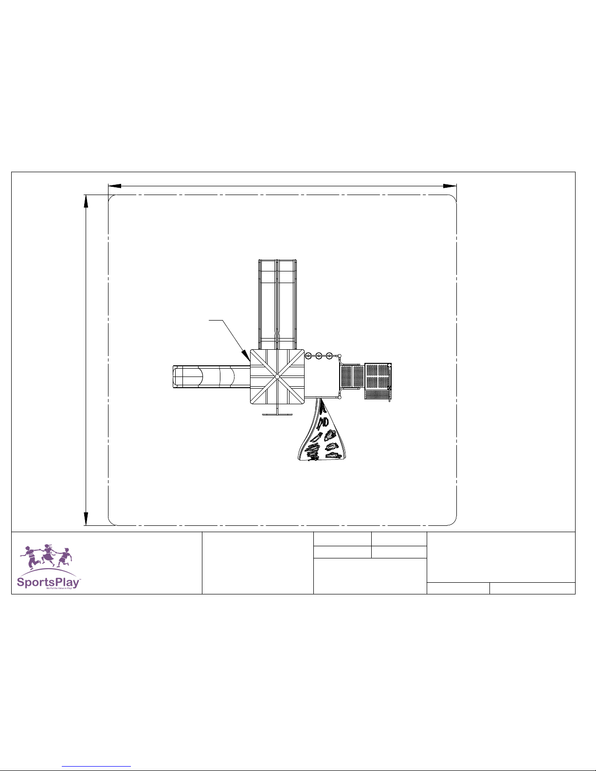
32'
31'
800-727-8180
Sheet 1 of 1
Scale: 1:60
Fax: 314-389-9034
www.sportsplayinc.com
Project: QS4_STD
Distributor: SportsPlay
DateDrawn By:
SportsPlay
SportsPlaySportsPlay
SportsPlay
E. Barron
00-00-10
Drawing Number: #911-255
ASTM: Compliant
CPSC: Compliant
5642 Natural Bridge
Size: 19' X 20'
Use Zone: 31' X 32'
Age Group: 5-12
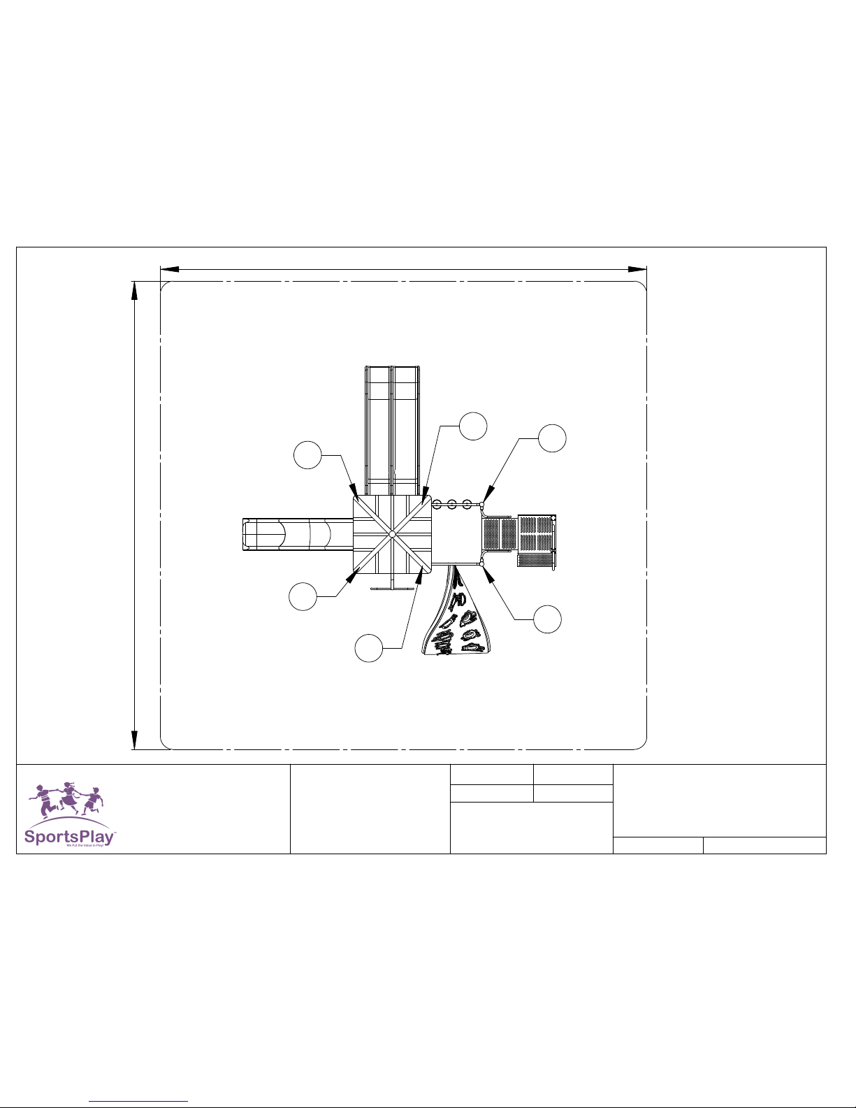
48"
Rail
36"
Slide
Triple
Slide
Wave
Climber
"U'
Climber
Aztec
Station
Transfer
Panel
Tic Tac Toe
Bump
Pyramid
Roof


800-727-8180
Sheet 1 of 1
Scale: 1:40
Fax: 314-389-9034
www.sportsplayinc.com
Project: QS4_STD
Distributor: SportsPlay
DateDrawn By:
SportsPlay
SportsPlaySportsPlay
SportsPlay
E.Barron
00-00-10
Drawing Number: #911-255
ASTM: Compliant
CPSC: Compliant
5642 Natural Bridge
Size: 19' X 20'
Use Zone: 31' X 32'
Age Group: 5-12
4"
20"
89"
20"
"46
"84
"46
"10
"23
"56
"24
"26
"2629
"
"
23"
46
"19
"69
16"

32'
31'
00-00-10
CPSC: Compliant
800-727-8180
Fax: 314-389-9034
Scale: 1:60
Sheet 1 of 1
Drawing Number: #911-255
ASTM: Compliant
Distributor: SportsPlay
DateDrawn By:
SportsPlay
SportsPlaySportsPlay
SportsPlay
Project: QS4_STD
www.sportsplayinc.com
E. Barron
5642 Natural Bridge
Size: 19' X 20'
Use Zone: 31' X 32'
Age Group: 5-12
P3
P4
P5
P6
36"
48"
P1
P2


Value Series
Installation Guide
2/28/11 V-C_OUTLINE.V1.0211
8
Important
Please read completely before beginning installation.
This equipment has been designed for safety as well as challenge and fun. This
equipment has been designed to reduce injuries and therefore must be installed
“Step by Step” per our Instructions.
The U.S. Consumer Product Safety Commission (CPSC) published a report
stating 79% of all playground injuries treated in U.S. Emergency Rooms was the
result of a fall. It is critical that you refer to the Protective Surfacing section of
these instructions, located on the next page prior to installing your playground.
As the owner you are responsible for the safe installation of not only the play
equipment, but also the safety of the site.
When your receive your playground
• Identify all parts by comparing them to the part list and component
instruction pages.
• Always compare the number of pallets, cartons or other items the BOL
has listed with the number actually received. Note the any discrepancies
on the BOL.
• Also note any obvious damage to the packing materials, pallets or
components on the BOL.
• Equipment should be inventoried and installed within a few days of
receipt. The packing materials are meant to protect the equipment
during shipping and not for storage. Heat, weather and sunlight can
damage the packing materials, which can impact the components. If
storage is required you must store the equipment in a controlled
environment away from heat, moisture and sunlight. SportsPlay
recommends carefully unpacking the unit and taking an inventory before
storing the equipment. Care should be taken with all powder coated and
thermoplastic-coated parts to prevent damage to the coating.
Additionally all plastic panels need to be stored flat to prevent warping.
• You have 30 days from receipt of your equipment to file a claim for
missing or damaged parts.
Before you begin
Review your playground footing and top view drawings to ensure your site is
large enough. The use zone for playground structures extends 6’ (72”) from
its perimeter. Remember that you may not overlap the use zone of any slide
with another playground. These guidelines are available from the CPSC
(contact information for the CPSC is located on the next page).
• Read through the entire instruction booklet before beginning the actual
installation.
• Before you begin preparing the site or digging any holes you must first
contact you local utility companies so they can visit the site and mark all
of the buried utilities. In the U.S. you may call 811 and your call will be
routed to your local utility center.
• This equipment was designed to install on a clear and level site. There
should be no more than 3” of grade variations in a 10’ span.
• Footing layout is the first critical step once the installation begins. Mark
all holes using the footing diagram. Prior to digging holes compare the
measurements from the footing diagram to the actual site markings to
ensure accuracy. Then check it again! (Footing info is located on pg 16
in this guide)
• Our posts are manufactured to accommodate 12” of protective surfacing.
• Evaluate the site for drainage. To ensure good drainage around the
equipment consult a local professional.

Value Series
Installation Guide
2/28/11 V-C_OUTLINE.V1.0211
9
• Do not leave the jobsite un-attended during installation unless all access
points to the play area are secure, all bolts and fasteners are tight and all
ground holes are covered.
• SportsPlay Equipment inc. has provided two warning labels that state:
“WARNING – Installation over a hard surface such as concrete, asphalt
or packed earth may result in serious injury or death from falls.” These
labels must be installed on vertical posts as per ASTM F1487.
Instructions for the placement of these labels are included in the
appendix of this booklet.
• SportsPlay will provide manufacturer identification labels that must be
installed on the structure during installation per ASTM F1487.
Installation instructions for these labels are included in the appendix of
this instruction manual.
• Labels must be replaced when they are no longer legible. Contact your
distributor for replacement labels.
Value Series
Installation Guide
2/28/11 V-C_OUTLINE.V1.0211
10
Safety Surfacing
WARNING! – INSTALLATION OVER A HARD SURFACE SUCH AS
CONCRETE, ASPHALT OR PACKED EARTH MAY RESULT IN
SERIOUS INJURY OR DEATH FROM A FALL
Because accidental falls are likely to occur around play equipment, SportsPlay
Equipment Inc. recommends that a resilient safety surfacing that will meet
standard ASTM F1292 be placed under and around the structure and extend
throughout the entire use zone.
SportsPlay Equipment Inc. does not manufacture safety surfacing. All
manufacturers of safety surfacing require different depths of surfacing for fall
heights. Consult your surfacing supplier about the required safety surfacing
depth for your play equipment.
SportsPlay Equipment Inc. manufactures all playgrounds to accommodate
12” of safety surfacing. If you intend to adjust the height of the surfacing
you will need to adjust the depth of the footing to accommodate the
surfacing height.
Refer to the CPSC Handbook for Public Playground Safety for the recommended
type and depth of the protective surfacing as well as all other playground safety
concerns.
For a copy of the most current issue of the CPSC Handbook for Public
Playground Safety, write to:
U.S. Consumer Product Safety Commission
Office of Information and Public Affairs
Washington DC, 20207
USA
Call - 1-800-638-2772 (US and Canada only)
Call - 301-504-0990
Direct Link - http://www.cpsc.gov
For a copy of either the standard for surfacing (ASTM F1292) or for play
equipment (ASTM 1487) write to:
American Society for Testing and Materials
100 Bar harbor drive
West Conshohocken PA, 19428-2959
USA
Call – 618-832-9585
Web Site – www.astm.org
You must consider the type of safety surfacing you will use before beginning
the installation process. There are two general types, organic/loose fill or
synthetic unitary (pour in place). You must know which type of surfacing
you are going to use prior to installing the playground. This unit was
designed for 12” of loose fill surfacing so if the customer wants to use a
synthetic unitary product that has a much smaller height than 12” you must
dig the footing holes deeper to allow for the difference.
If loose fill surface material is to be used (example: wood mulch) you will
need to consider containment borders. There are many products to choose
from including hard plastic and natural products such as wood (Creosoted
railroad ties are NOT recommended for use as borders in a play area). Loose
fill materials are easily displaced so use of some type of containment border
is necessary to keep the surfacing material inside the intended area. Some
customers also prefer to have a weed mat installed to prevent weed growth.
Choose a mat that will prevent growth but will also allow for drainage.

Value Series
Installation Guide
2/28/11 V-C_OUTLINE.V1.0211
11
Tools and Materials
List is for tools and materials needed that are not included with the
playground
Follow manufacturer’s guidelines for proper use of tools and materials.
• The best method (also the easiest) to dig the postholes is using a
tractor with a 12” auger attachment.
• Shovels (long handled spades)
• Post hole digger
• Wheelbarrow
• Large construction bar (5’)
• Pry bar
• Claw hammer
• Large dead-blow rubber hammer
• Small sledgehammer to use in blocking the posts
• Vise grips (various sizes and styles)
• Strong and sturdy step ladders
• Socket set’s (1/2” & 3/8” drive)
• Extension cords & power supply
• Drills (1/2” and 3/8”)
• Drill bits and spade bits
• Levels – Magnetic torpedo and 4’ long levels
• Scrap lumber to use for shims in post holes to keep posts level
• Blocking materials for the post holes (bricks, concrete blocks, etc.)
• 4’ Bar Clamp
• Files and sand paper
• Safety surfacing
• Spray paint to mark holes
• String line
• Cement (2,500 psi minimum)
• Straight line or transit level (and tripod) for ensuring hole depths are
at the same level

Value Series
Installation Guide
2/28/11 V-C_OUTLINE.V1.0211
12
BEFORE STARTING INSTALLATION OF YOUR PLAYGROUND,
PLEASE READ INSTRUCTIONS THOROUGHLY.
BEFORE BEGINNING
SITE REQUIREMENTS
The Playground system is designed to suit a level site. Should there be any falls
or slopes on the site; care should be taken to accommodate the entry and exit points
and to maintain the correct height. There should not be more than 3” of drop in grade
per every 10’.
The site must be inspected for natural obstacles such as roots or rocks that may
be a trip hazard, poor drainage and sharp objects such as glass.
Every state has different rules and regulations governing digging, some are
stricter than others. In addition, 62 separate One Call Centers serve different
areas of the country; now 811 will connect you directly to your local One Call
Center. Prior to digging, be sure to call 811 or the local One Call Center to
prevent accidentally disrupting local utility service.
MAINTENANCE:
As an owner, it is most important that you are aware of your responsibility to
insure safe use of your new equipment. It is necessary to install equipment
according to the installation instructions provided and inspect the equipment at
regular intervals. During inspection, if any part is found damaged or excessively worn,
equipment should be closed immediately. A maintenance section is included in the
appendix of this instruction booklet.
If a part is missing or damaged the playground must be put out of service while
the part is replaced. Lack of maintenance will result in premature wear, reduced
life expectancy, and possible failure that may result in injury.
All SportsPlay Equipment play events have been engineered to meet all
applicable safety guidelines, but if installed
Improperly, these problems may occur:
• Entrapment gaps (between 3 1/2” and 9”)
• String Entanglements
• Protrusions
Make sure that any bolt end that protrudes more than 2 threads past the face of the
nut is trimmed and de-burred smoothly. Always double-check your work.
Installation must adhere to the manufacturer’s assembly manual and all other applicable
safety guidelines.
PLAY AREA:
The area immediately above and around the play structure must be free of any
obstructions such as:
• Trees
• Other Play Equipment
• Buildings
• Overhead Power lines
Make sure the play area has all the required safety surfacing and the
minimum fall zones as required by the safety guidelines. These guidelines can
be found at www.cpsc.gov.
CHILDREN MUST BE SUPERVISED AT ALL TIMES. No playground is
safe without adult supervision!
There may be situations that require you to modify the layout or use your own
judgment. If you have any questions contact you distributor.
Reading this entire manual before beginning the installation will help you to
ensure your equipment is installed and maintained correctly.
The use zone for this equipment shall extend a minimum of 6’ in all directions
from the perimeter of the equipment.

Value Series
Installation Guide
2/28/11 V-C_OUTLINE.V1.0211
13
The use zone for adjacent stationary equipment may overlap. If the deck height
for that equipment is no more than 30” above the protective surfacing the use
zone is 6’.
The use zone for adjacent stationary equipment may overlap. If the deck height
for that equipment is more than 30” above the protective surfacing the use zone
is 9’.
Value Series
Installation Guide
2/28/11 V-C_OUTLINE.V1.0211
14
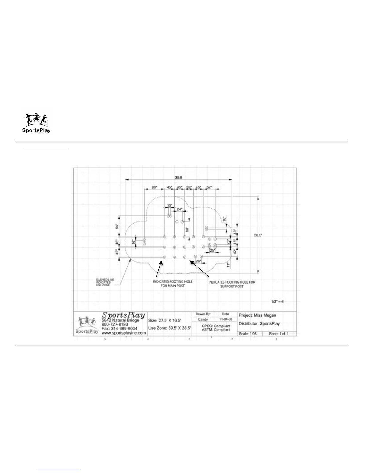
Installation Punch List
Footing Layout Example
Value Series
Installation Guide
2/28/11 V-C_OUTLINE.V1.0211
15
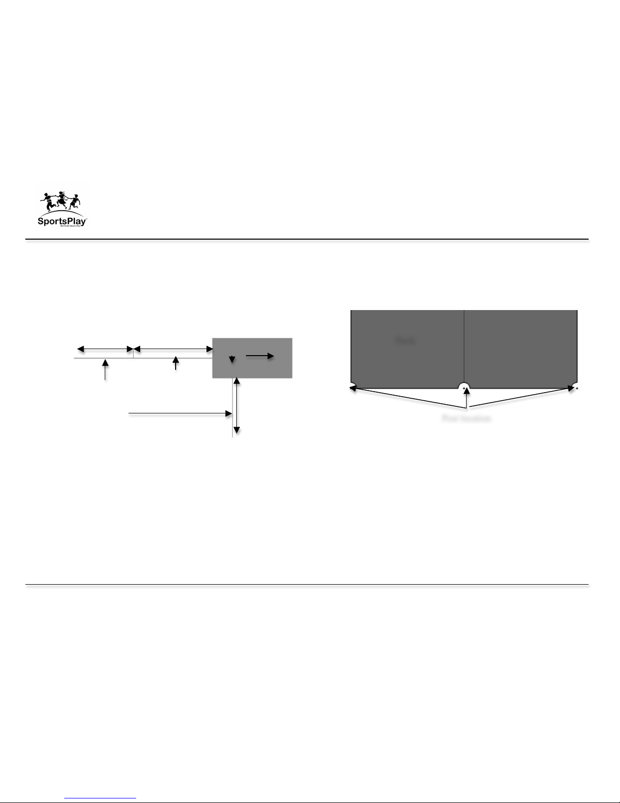
Step 1: Layout
1. Lay decks on ground in the desired location using the top view layout
drawing. Measure from each deck to ensure there is adequate space for
any component and the components fall zone. Below is an example of
how to layout your decks so you can mark the location of the holes for
the main posts and verify the required distance for a fall zone. This
drawing is a standard drawing and does not represent the actual
playground you are installing.
2. Most installers like to orientate the playground so that the entry point of
the playground (primarily a transfer station) is facing either the sidewalk
or the direction from which the children are entering the play area.
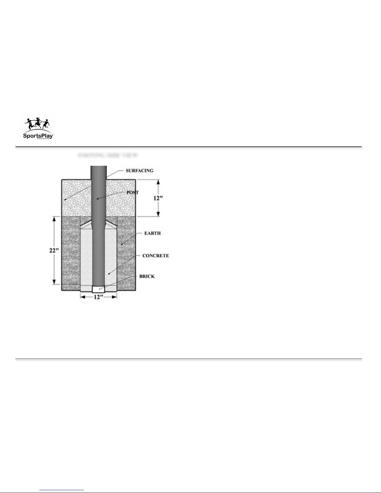
Step 2: Holes
1. If the site grade is not level you have to adjust the footing depth to
maintain a level footing. Check with building codes to ensure you meet
required hole depth and width. If a deeper footing is required you must
add blocking materials to the hole to keep the post depth in accordance
with the footing side view drawing on the next page.
2. Once the decks are in the desired location within the play area and the
decks are flush with each other, mark the locations of the post by
inserting a stake into the center of each post location (see drawing below
for an example). If using spray paint to mark location please be careful
not to spray the deck.
3. Match the post location marks with the footing layout in the front of this
booklet (an example of how to identify which holes are for the main
posts and which are for support posts is on the previous page). Dig your
holes using the main post footing drawing below. If your surface grade
is not level you should start with the lowest point and use that hole
depth to level all other holes too. The footing drawing below indicates a
depth of 22” plus the thickness of a brick (or the thickness of whatever
blocking material you will use instead of a brick). This depth is for 12”
of surfacing only. If you are using something other than 12” of
surfacing, such as 3” of rubber your hole depth would have to be 31”
plus the thickness of a brick to allow for less surfacing material.
(Footing depths for support posts such as slide legs are listed in the
component assembly instructions.
Decks
Component
length
6’ fall zone
from the end
of the
component
Deck
Post location
Value Series
Installation Guide
2/28/11 V-C_OUTLINE.V1.0211
16
4. It is recommended that you use a transit to level the remaining postholes
to the first hole in order to ensure that the posts are level.
5. Using the post identification drawing (4th page of this booklet) identify
which post goes in each hole by matching the number on the post with
the number on the drawing.
Step 3: Deck, Post & Component Installation
1. The easiest way to install the playground is by starting with the central
deck and then work out. We recommend installing the posts and central
deck and once the post and deck are square and level you may add the
concrete (concrete with a minimum of 2,500 psi should be used). Mix
concrete per manufacturers instructions and let it cure for at least 24
hours before continuing.
2. NEVER LEAVE THE INSTALLATION SITE UNATTENDED
WITHOUT ROPING OFF THE AREA AND EQUIPMENT,
INSTALLING ALL HARDWARE, SECURING TOOLS AND
EQUIPMENT, AND COVERING OPEN HOLES WITH A RIGID
MATERIAL (PLYWOOD). CHILDREN WILL TRY TO USE
THE EQUIPMENT EVEN THOUGH ITS NOT FULLY
ASSEMBLED. YOU MUST TAKE ACTION TO PREVENT
INJURY AND DAMAGE.
3. Once the first deck is installed and the concrete has set for 24 hours you
can install the remaining decks working out from the first deck ensuring
all decks and posts are square and level as you go.
4. Level and plum all posts and decks and then brace them in position.
5. Beginning at the lowest deck, install all playground components. When
installing the four hole brackets be sure to orientate the bracket so that
the setscrew faces down. Use the footing layout at the beginning of this
booklet to layout your component holes. Once the entire playground has
been installed and the entire unit is level you may start adding the
concrete.
FOOTING SIDE VIEW

Value Series
Installation Guide
2/28/11 V-C_OUTLINE.V1.0211
17
Step 4: Concrete
1. Verify all posts, decks and components are tight, level and square. Once
the unit is verified to be level and square you may start installing
concrete. You must use concrete with a minimum of 2,500 psi.
2. Always pre mix the concrete to the manufactures directions before
pouring it into the hole. Never put dry concrete in the hole. Typically
each main posthole requires two 80-pound bags of concrete.
3. Allow concrete to set in accordance with manufacturers directions. Fill
holes too about 2” below the surface with concrete. Once the hole has
been filled with concrete, slope the top of the concrete down and away
from the post to keep water from seeping between the post and the
concrete.
4. Secure playground area to prevent access while the concrete is setting
for a minimum of 48 hours.
5. SportsPlay recommends having a CPSI (certified playground safety
inspector) present during installation. If that’s not possible you should
have the completed playground (after surfacing is in place) inspected by
a CPSI.
Step 5: Last Step
1. After concrete has completely set, backfill all holes with dirt.
2. Install surfacing label, 12” from dirt surface on main posts for mulch.
3. Install surfacing.
Value Series
Installation Guide
2/28/11 V-C_OUTLINE.V1.0211
18
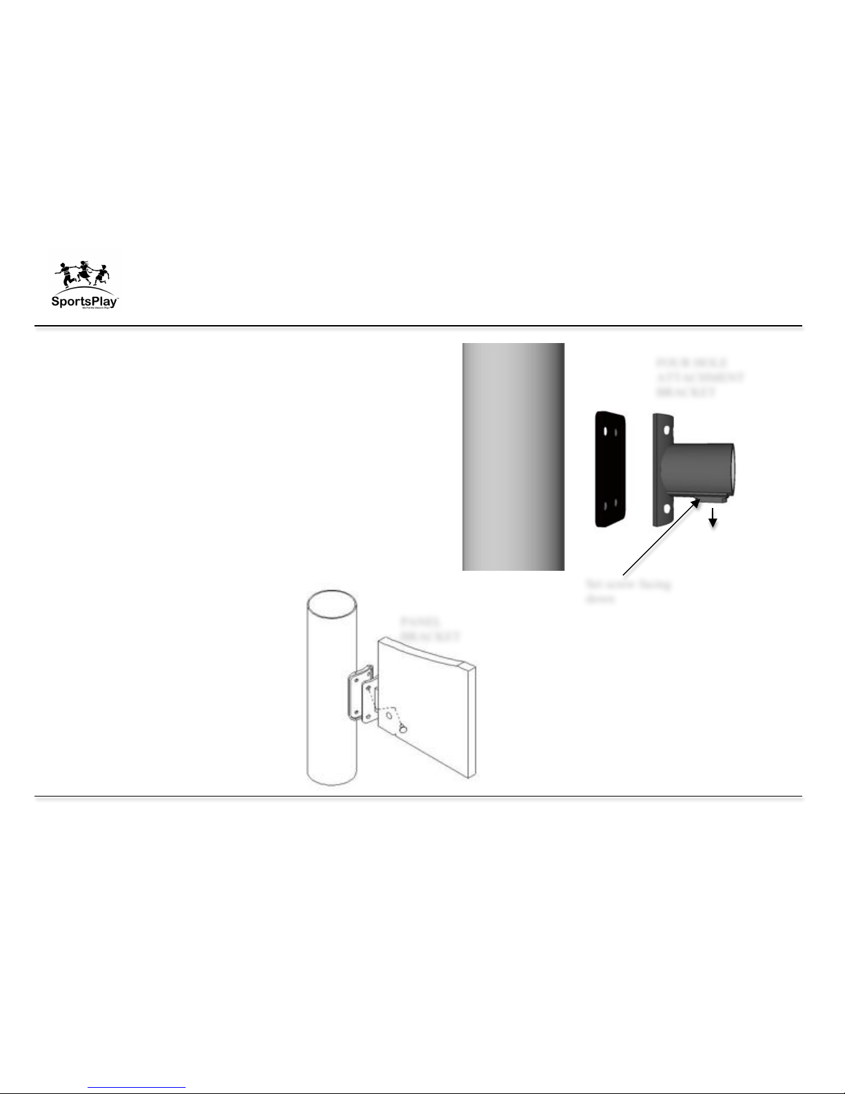
Four Hole Bracket & Panel Bracket Installation
Tip for installation
• Use the #7 drill bit to pre-drill all holes when connecting the bracket
to the post if you are having trouble with the self-tapping screws
Installation
• Always install the brackets with the set screw facing down (refer to
the drawing on the right)
• Always install the rubber gasket with the brackets
• After you have installed the brackets and the component completely
verify the set screw is tightly in place and smooth out all sharp
edges and points
• Use the screw bit included with the hardware
• Do not over tighten screws
Set screw facing
down
PANEL
BRACKET
FOUR HOLE
ATTACHMENT
BRACKET
Value Series
Installation Guide
2/28/11 V-C_OUTLINE.V1.0211
19
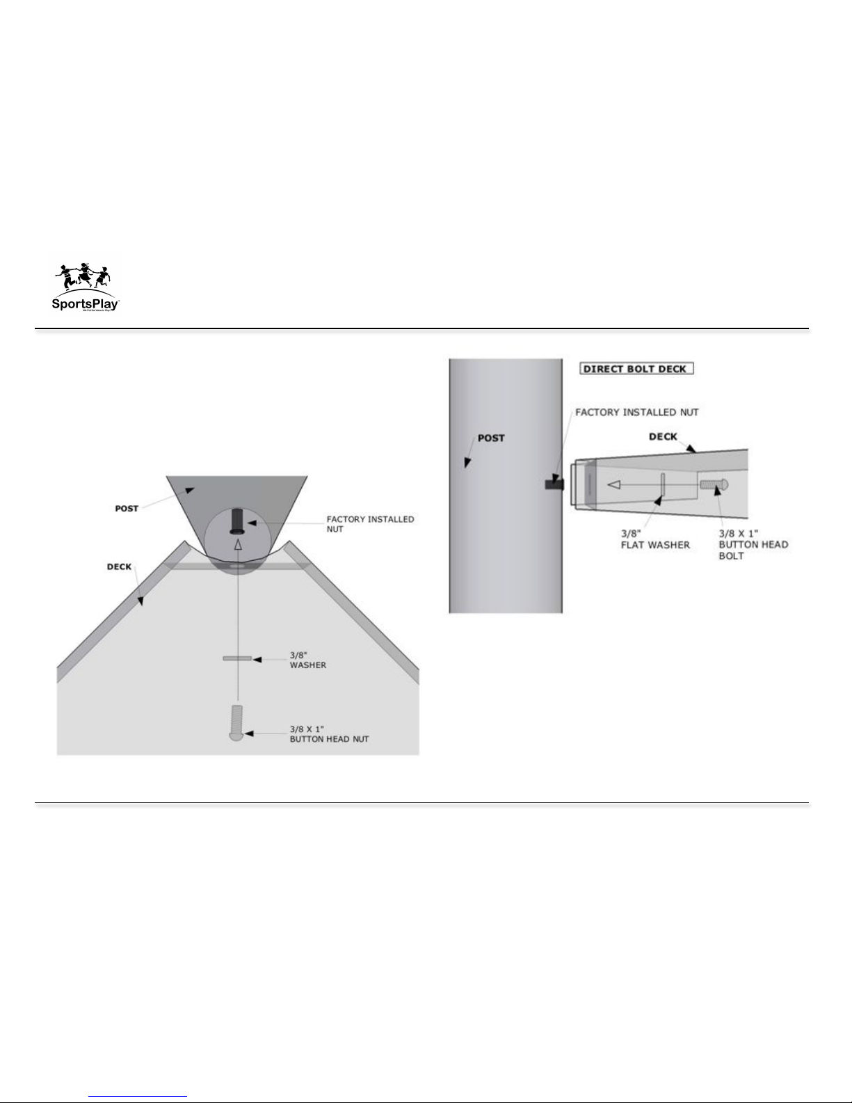
Direct Bolt Deck
While two people position and hold the deck in place, insert the
deck bolt and washer through the deck and into the factory installed
nut on the post.
To ensure proper placement, refer to the layout drawing and the
post id drawing at the beginning of this guide.

Value Series
Installation Guide
2/28/11 V-C_OUTLINE.V1.0211
20
Other Installation Tips
• When attaching a deck to a post sometimes the factory installed nuts
will spin when tightening the bolt. If this happens simply slide a slim
flathead screw driver in between the deck and the post and slightly pry
on the installed nut to keep it from spinning.
• If you are mocking up components with the intention of removing
the hardware at some point, you may want to apply lubricating oil to
the hardware. Stainless steel hardware has a tendency to seize so if you
are planning on removing the hardware you may want to apply lubricant
to prevent this.
• Pre-drill the holes for the four hole bracket in the posts with the #7
drill bit included with the hardware
• Unless specified in the specific component instruction step, do not
tighten the hardware completely until the entire unit is assembled.


Value Series
Installation Guide
2/28/11 V-C_OUTLINE.V1.0211
21
SUPERVISION GUIDE
Although the equipment is designed, installed and maintained in accordance with
all safety guidelines adult supervision is required.
Not all equipment is appropriate for all ages. Direct children to age appropriate
equipment.
Younger children will require more supervision than older children.
While eliminating accidents is not likely, following these guidelines will help
minimize accidents.
Basic playground safety for supervisors:
! Make sure all safety surfacing is in place and at the correct height.
Inspect area for hard or sharp objects and remove them.
! No dangerous horseplay in the play area. (Jumping from dangerous
heights, displacing of surfacing, etc…)
! Inspecting for missing or broken equipment. (Do not allow children to
play on broken equipment or equipment with missing components).
! Make sure there are no unsafe modifications (especially ropes tied to
equipment). Remove all unsafe modifications and close the equipment
for play until they are removed.
! Keep children in the designated play area.
! Do not let children play on wet equipment.
! Prevent overcrowding on play equipment.
! Loose clothing, hoods, strings or jewelry shall be tight or not worn
while playing to prevent strangulation.
! Ensure the temperature of the equipment is not hazardous. Direct
sunlight exposure can increase the temperature of the equipment high
enough to cause injury.
! Inspect the playground every day using the General Inspection Checklist
located in the appendix of this manual
o The easiest method for performing the daily inspection with the
checklist is to laminate the checklist and use a dry erase marker
to mark the items off before opening the play area

 Loading...