

Sportsliter Solutions Two circuit remote ballast User Manual
Installation Instructions
TWO CIRCUIT REMOTE BALLAST
INSTALLATION AND SERVICING INSTRUCTIONS
Wiring Instructions: (See Figures 2 & 3)
WARNING!
• Dangerous voltages exist within this product.
• This enclosure includes two electrical supply circuits. To reduce fire and shock hazards
disconnect power to both circuits before servicing.
• To reduce the risk of injury, operate and maintain to meet all applicable codes.
• Installation is to be performed by a qualified electrician only.
• Provide proper ground for all system components.
• Read and follow all instructions and labels before and during installation.
• Failure to properly install this product will void manufacturer’s warranty.
• Handle and secure so ballast enclosure cannot fall.
• Use protective equipment to avoid injury during installation of this heavy product.
• Do not route wiring through top of enclosure.
NOTE:
A complete system includes the ballast enclosure, lighting fixtures, wiring harness,
crossarms and poles.
This ballast enclosure should be installed at a minimum height of 10 feet (3 meters)
above grade.
Enclosure Installation:
(Figures 1, 2, & 3) Important: Installation requires the use of a pole
equipped with mounting couplings and wireway. (Figure 1)
1. Remove peel strip from gasket supplied in hardware bag.
2. Apply gasket to the back of enclosure around the 2 (63.5mmx114.3mm) hole. (Figure 3)
3. Install bolt (2) and lockwasher (3) in the top coupling. (Figure 2) Leave
1” (25.4mm) of thread exposed.
4. Position lift bracket (4) over the bolt (2) and lockwasher (3)
NOTE: The top of keyhole in bracket must contact the bolt to support
the 280 pound (127Kg) enclosure.
5. Align the wireway opening in the enclosure with the wireway opening in
the pole. Do not damage gasket!
6. Install bolt, lockwasher and flatwasher through hole inside of enclosure
and into the coupling in pole.
7. Tighten both bolts to a minimum of 40ft/lbs.
8. Seal all openings between pole and enclosure.
1
⁄2”x4-1⁄2”
Wiring and Electrical Instructions:
• The enclosure includes two electrical supply circuits.
• The enclosure voltage must match the supply voltage.
• Standard wiring is single phase. Three phase requires a- “T” on the
catalog number. (Consult factory)
• Total operating amps for each supply circuit is shown on the electrical
datamarker located near each switch
• Enclosure are factory wired to operate as a separate unit. (Contact factory
multiple enclosures in series)
• Enclosure includes factory fusing of all branch circuits.
• Separate internal electrical switching is included for each circuit:
Thermal Magnetic Breaker is standard for 208v, 220v and 240v
Load Break Switch is standard for 277v, 347v and 480v
“-TB” indicates Thermal Magnetic Breaker for 277, 347v and 480v.
Figure 1
SLS0036 SLS 2 Remote Ballast Instruction-A 1/14
Drawing Number: 268-1220-9901

TWO CIRCUIT REMOTE BALLAST
INSTALLATION AND SERVICING INSTRUCTIONS
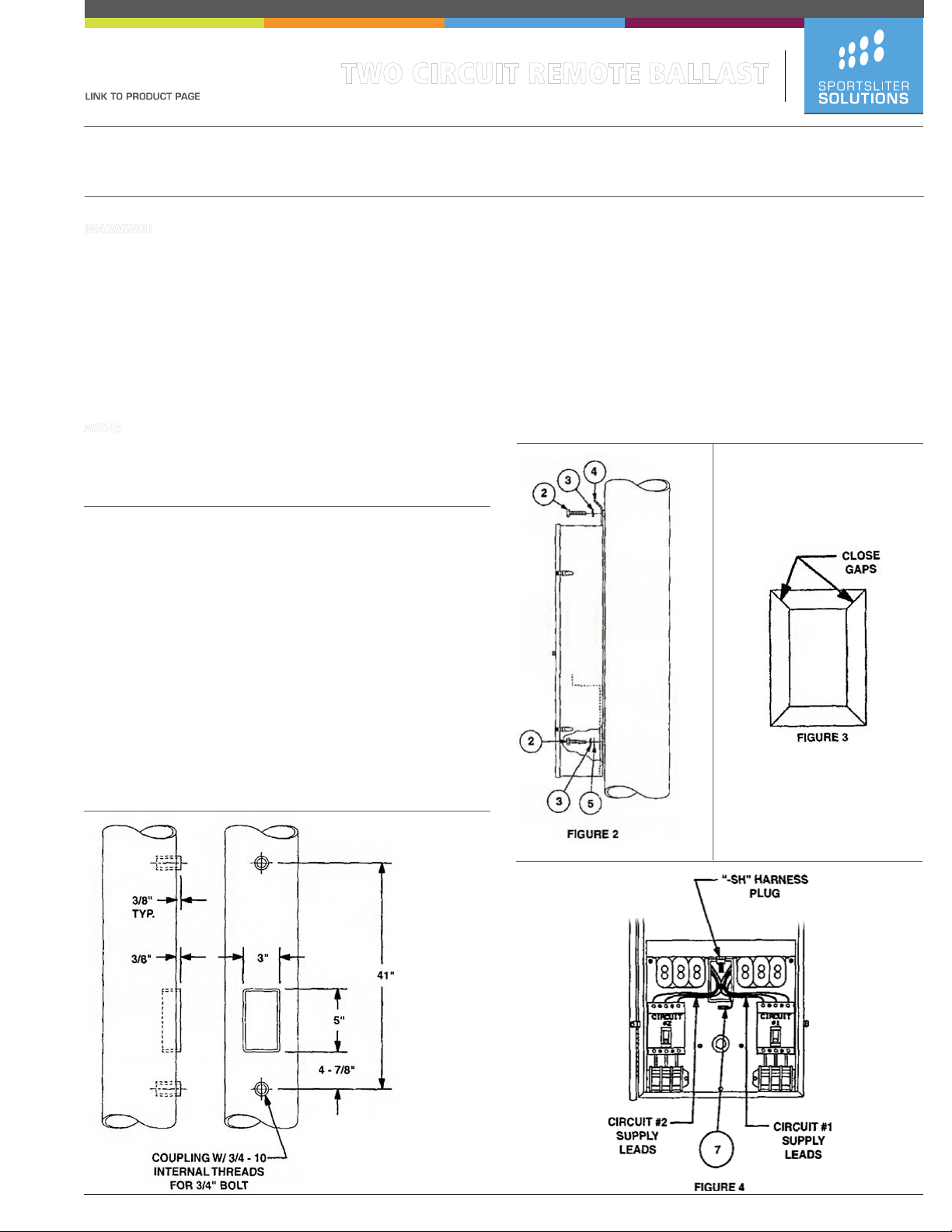
Supply Wiring:
1. Connect the supply wires to the proper lugs on switch.
2. Connect ground wire (6) to the ground lug (7) (Fig.4)
3. Provide effective strain relief to prevent wire damage.
4. Comply with all national and local electrical codes.
Caution: Protect exposed wires with approved insulators.
Fixture Wiring into Enclosure:
1. Connect the male plug of wiring harness and the female harness plug
inside enclosure. (Figure 4) Snap securely.
2. Enclosure shall be properly grounded.
3. Close door and engage the latches. A lock is optional.
These instructions are not intended to be a comprehensive guide to all
installation issues. The installer is responsible for safe, secure mounting
suitable for the application. Once the enclosure is installed, give these
instructions to the equipment owner.
Due to our continued efforts to improve our products, specifications are subject to change without notice.
Copyright © 2013 Hubbell Lighting All Rights Reserved.
For more information visit our web site: http://www.sportslighting.com/
SLS0036 SLS 2 Remote Ballast Instruction-A 1/14
Drawing Number: 268-1220-9901
 Loading...