

Sportsliter Solutions Remote Yoke Horizontal Optics User Manual
REMOTE YOKE HEAD HORIZONTAL OPTICS
Installation Instructions
INSTALLATION AND SERVICING INSTRUCTIONS
GENERAL SAFETY WARNING!
Dangerous voltages exist within these fixtures and all precautions usually observed in
handling high voltage equipment should be observed when replacing lamps, installing or
otherwise servicing these fixtures.
DO NOT AIM ABOVE HORIZONTAL
WARNING!
To reduce fire and shock hazard: Disconnect power before servicing. Install and maintain
fixture to meet all applicable codes. Ensure that fixtures and wiring are properly
grounded. Read and follow all instructions, electrical data markers, lamp carton warnings
and wiring labels before installing. Installation of fixture is to be preformed by a qualified,
licensed electrician only. The installer of this fixture is responsible for safe, secure
mounting suitable for the application. Once fixture is installed, give these instructions to
the equipment owner.
CAUTION!
High temperature tempered glass sometimes ruptures spontaneously.
Install to minimize hazard of falling diced glass.
Unpacking Instructions:
While unpacking, it is important to verify the location of all parts before
discarding any packaging materials.
Assembly Instructions:
1. Open lens assembly
2. Install lamp. Secure lamp with lamp end support wire form.
3. Close lens assembly.
4. Ensure the gasket is seated properly and snap the (4) latches over the
reflector flange.
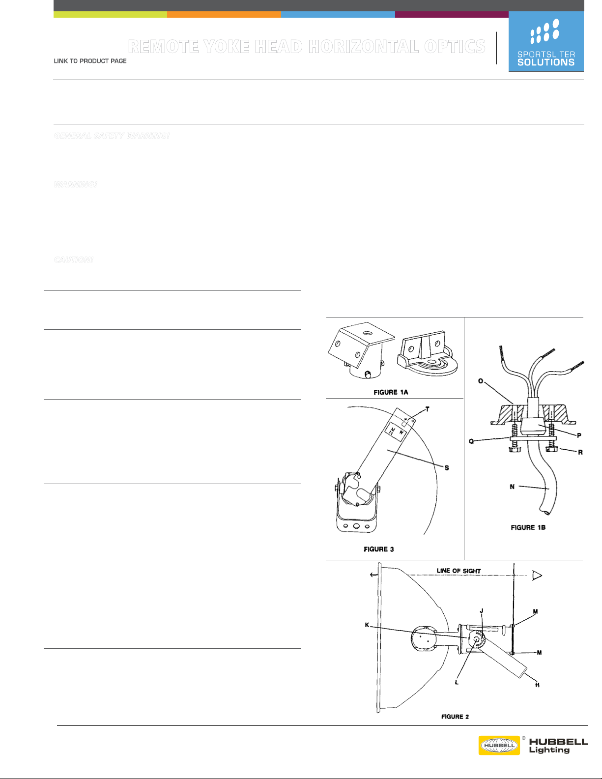
Mounting Instructions (See Figure 1a)
1. Install the fixture by mounting the yoke to the appropriate auxiliary
mounting adapter (4090 or 4042C) with (2)
nuts or (1)
3
⁄4” bolt, washer and nut supplied by others.
1
⁄2 ” bolts, washers and
(Consult producr selections guide for available mounting adapters.)
2. Attach the fixture to your pole or other mounting device. Ensure that
once installed, the fixture’s cord exit hole and reflectors/lens hinge are
facing downward.
5. Place keyhole slot in aiming holes located as shown in figure 3.
6. Be sure that the aiming sight bracket (S) slides all the way down and is
firmly seated under BOTH screw heads and tighten screws (M)
7. Look through the holes at the end of the aiming sight bracket (S). Use
the hole above the “M” for medium and narrow, “W”for wide
distribution reflectors.
8. Align the center of the hole with TOP LEFT edge of the door
retaining latch (T).
9. Aim the fixture by aligning the hole in the aiming bracket and the left
edge of the latch with the desired aiming location.
10. Once the fixture is aimed, tighten only the yoke bolt (L) on the side
opposite the repositioning stop (K).
11. Tighten the bolts holding the auxiliary mounting adapter to the pole or
mounting surface.
12. Rotate the repositioning stop (K) until the tab resets firmly against the
yoke (H) and tighten the repositioning stop bolt (J). Tighten the other
yoke bolt (L).
13. Remove the aiming sight bracket (S) and save the bracket for the owner.
14. Tighten the (2) cover screws (M).
Wiring Instructions: (See Figures 1b & 2)
1. Loosen the (2) wiring cover screws (M) and swing the cover away to
expose the wiring compartment.
2. Feed supply cord (N) into the wiring compartment through the
wiring hole (O) in the bottom of the socket housing
3. Feed supply cord through the appropriate rubber seal (P) and through the
center hole in the retaining plate.
4. Install the retaining plate using (2) #10-24 screws (R) provided. When
installed, the end of the cord’s outer jacket should not extend beyond
1
⁄2”
into the wiring compartment.
5. Tighten the (2) screws (R) to retain the supply cord.
6. Connect supply power leads to socket leads in accordance with
local and NEC Codes.
7. Attach ground lead to green ground screw inside wiring compartment
and replace cover, ensuring that no wires are pinched inside housing.
8. Replace wiring cover and tighten screws (M)
Target Aiming Instructions: (See Figures 2
&3)
1. Loosen (2) yoke bolts (L)
2. Loosen repositioning stop bolt (J)
3. Loosen the bolts holding the auxiliary mounting adapter to the pole or
mounting surface.
4. Loosen but do not remove (2) wiring compartment cover screws (M)
Due to our continued efforts to improve our products, specifications are subject to change without notice.
Copyright © 2013 Hubbell Lighting All Rights Reserved.
For more information visit our web site: http://www.sportslighting.com/
SLS0038 Remote Yoke Head Horizontal Optics 1/14
Drawing Number: 268-1089-9901
 Loading...