

Page 1
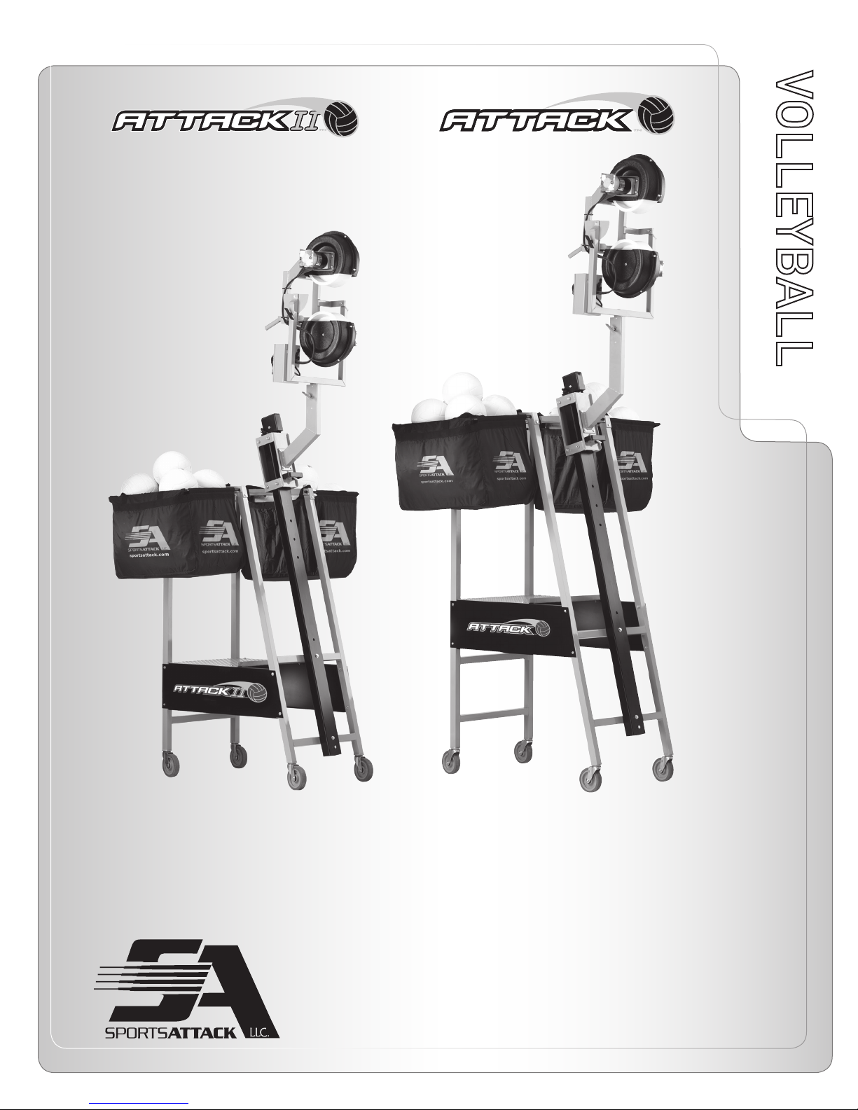
VOLLEYBALL MACHINE
VOLLEYBALLVOLLEYBALL
Includes: OPERATION · SETUP · USE & CARE · SERVICE
REV083115
ATTACK™ AND ATTACKII™ VOLLEYBALL MACHINE
PATENTS APPLIED FOR
INSTRUCTION MANUAL
SPORTS ATTACK, LLC. • 800-717-4251 • sportsattack.com
Page 2
WARRANTY STATEMENT
What is most important to Sports Attack is that your machine meets your expectations of
quality and performance. We stand behind the material and workmanship of our machines
for five (5) years from the date or original purchase for institutional and residential use and
one (1) year for commercial environments, with the following exceptions:
-Throwing Wheels are warranted for two (2) years;
-Electronic Controller is warranted for two (2) years; and,
-Throwing Wheel Motors are warranted for two (2) years.
This warranty excludes any cosmetic issues or normal wear and tear of the unit, and is not in
effect if the machine has been misused, misapplied, improperly assembled, or modified without the express written permission of Sports Attack. In addition, this warranty does not apply
to damage in transit, in any accident unrelated to the direct operation of the equipment, or
by fire, flood or act of God.
If you encounter any issues during the warranty period, Sports Attack will quickly get your
machine back in working order. If the warranty repair involves a replacement part, we will
make sure you get both the part and easy instructions for replacement at no cost to you. If a
service person is needed, Sports Attack will pay the pre-approved labor charge to get your
machine back in working order.
Please know that any problem can quickly be resolved with a phone call to our experienced,
responsive customer service department at 800.717.4251. We are here to answer your questions and to make sure your machine provides you years of service.
RETURNS
Sports Attack manufactures the highest quality sports training equipment in the world. If for
any reason you are not satisfied, a machine can be returned within 30 days of receipt for any
reason for a full refund less a 10% restocking fee. Cost of shipping the unit back to Sports Attack will also be the responsibility of the purchaser. Please note that the refund amount may
be reduced by any non-cosmetic damage to the machine.
If you have any questions or concerns, please give our experienced, responsive customer service
department a call at 800.717.4251.
SHIPPING DAMAGE CLAIMS PROCEDURE
NOTE: For your protection, please note that equipment in this shipment was carefully inspected and packaged by skilled personnel before leaving the factory.
To register the Warranty,
please go to our website:
www.sportsattack.com/warranty
For repairs and service after the
Warranty period, please call:
Sports Attack
Customer Service Dept.
Ph 800-717-4251
Fx 775-345-2883
RETURNS
To return an item, please
contact our Customer Service
Department at 800-717-4251.
A 15% restocking fee will be
charged for any items accepted
for return. It is the customer’s
responsibility to handle the
repacking and shipment (as well
as all associated fees) back to
Sports Attack.
No returns will be accepted after
30 days of receiving product.
Warranty/Shipping
Upon acceptance of this shipment, the transportation company assumes full responsibility
for its safe delivery.
IF SHIPMENT ARRIVES DAMAGED:
1. VISIBLE LOSS OR DAMAGE: Be certain that any visible loss or damage is noted on the
freight bill or express receipt, and that the note of loss or damage is signed by the
delivery person.
2. FILE CLAIM FOR DAMAGE IMMEDIATELY: Regardless of the extent of the damage.
3. CONCEALED LOSS OR DAMAGE: If damage is unnoticed until the merchandise is
unpacked, notify the transportation company or carrier immediately, and file
“CONCEALED DAMAGE” claim with them. This must be done within fifteen (15) days
from the date the delivery was made to you. Be sure to retain the container
for inspection.
Sports Attack, LLC. cannot assume liability for damage or loss incurred in transit. We will,
however, at your request, supply you with the necessary documents to support your claim.
ATTACK™ AND ATTACKII™ VOLLEYBALL MACHINE
SPORTS ATTACK, LLC. • 800-717-4251 • sportsattack.com
xi
Page 3
TABLE OF CONTENTS
Warranty Statement ...................................................................xi
Safety Instructions .................................................................... 4
ATTACK and ATTACKII VOLLEYBALL ASSEMBLY INSTRUCTIONS
Assembly Instructions .............................................................. 5
Attack Assembly Figures............................................................ 6
AttackII Assembly Figures........................................................... 7
Bolt Schedule .....................................................................8-9
Replacing Throwing Head..........................................................10
Operation ........................................................................11
Shutting Down.................................................................... 12
MAINTENANCE & SERVICE
Care, Cleaning & Maintenance......................................................13
Component Replacement
Wheel........................................................................... 14
Motor ...........................................................................14
Controller .......................................................................15
Increasing Bungee Tension.........................................................16
Attack Component Parts...........................................................17
AttackII Component Parts.......................................................... 18
Parts List.......................................................................19-20
Table of Contents/Introduction
SPORTS ATTACK
Product Line ...................................................................21-22
INTRODUCTION
Thank You for purchasing this Sports Attack LLC. equipment.
Proper assembly, careful operation and consistent maintenance of this equipment will
ensure that it gives you the very best performance and a long, economical service life.
This manual contains the information needed to properly setup the Attack and AttackII,
and to use, care for and maintain the Attack and AttackII in a manner which will ensure
their optimum performance.
RECEIVING THE PRODUCT
Please check the contents of your boxes to ensure you have received all parts for
the machine. If anything is missing or damaged, call Sports Attack Customer Service,
800-717-4251. If the product or package has been damaged in shipping, note on
shipping tag, save all evidence of damage along with related documents and contact
the shipper immediately.
ATTACK™ AND ATTACKII™ VOLLEYBALL MACHINE
SPORTS ATTACK, LLC. • 800-717-4251 • sportsattack.com
1
Page 4

SAFETY INSTRUCTIONS
ELECTRICAL SAFETY
Use a 115 volt single phase 3-wire grounded
power source.
Up to 200 ft. from power source,
use a minimum #14/3 grounded 3-wire
extension cord.
Over 200 ft. from power source, consult
a licensed electrician for required power
cord size.
OPTION B 208/220/230V
Green = Earth
White or Blue = Neutral
Black or Brown = Line
OPERATING SAFETY
1. Never reach hands into throwing wheel area.
2. Always use the Attack or AttackII with throwing wheel shields in place.
3. Use the Attack or AttackII only under adult supervision.
4. Use the Attack or AttackII only for their intended purpose.
5. Do not operate the Attack or AttackII with a damaged cord or plug, if the machine
malfunctions or has been damaged.
6. Check machine before turning “ON” to make sure there are no foreign object
in feed chute.
7. If ball becomes lodged and stops motor, immediately turn machine off
before dislodging.
8. To dislodge ball from throwing wheel, unplug machine and push ball through chute.
Do not reach hand into feed chute with the machine running.
WARNING
PERSONAL INJURY
HAZARD
Carefully read all instructions
in this manual, and all labels
and warnings on the Attack or
AttackII before using either of
the machines.
Use machine only under adult
supervision. Failure to operate
Attack or AttackII as described in
this manual can result in severe
personal injury or death.
ELECTRICAL SHOCK
HAZARD
Attack or AttackII must be
connected to a properly grounded
electrical receptacle.
•
Do not operate on wet ground.
WARNING
PERSONAL INJURY
HAZARD
Keep hands away from throwing
wheels anytime the machine is
connected to a power source.
•
Carefully check the Attack or
AttackII for completeness and
condition before connecting to
electrical power.
Attack & AttackII Safety Instructions
9. Only one person at a time should operate the Attack or AttackII.
10. Be sure chain is locked when standing on platform.
11. Do not allow anyone to walk directly in front of the machine. Keep face and hands
away from ball exit.
12. A ball should always be test thrown from the Attack or AttackII before beginning
any drill. Throw several balls to verify end location.
13. Keep hands, hair and loose clothing away from moving parts.
14. Do not use near water or use damp or wet balls.
ATTACK™ AND ATTACKII™ VOLLEYBALL MACHINE
SPORTS ATTACK, LLC. • 800-717-4251 • sportsattack.com
EQUIPMENT ELECTRI-
CAL
DAMAGE
DO NOT plug in or energize the
equipment until all Assembly and
Operation Instructions are read
and followed.
2
Page 5
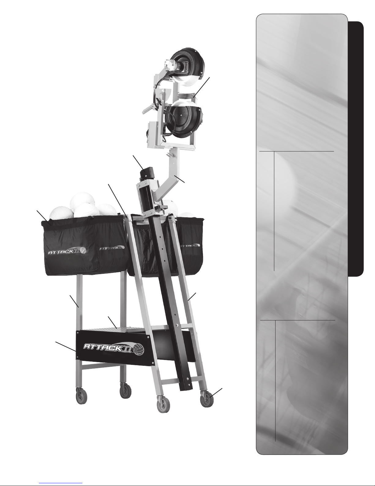
COMPONENT DIAGRAM & PACKING LIST ATTACK & ATTACKII
Yoke & Head
Assembly
CAUTION
PERSONAL INJURY
HAZARD
Failure to use the special tool
provided to install the casters
could result in personal injury.
EQUIPMENT DAMAGE
Failure to use the special tool
provided to install the casters
could result in equipment damage.
ASSEMBLY PARTS
Attack & AttackII Component Parts
Optional
Ball Bags
Rear Frame
Assembly
Right-hand
& Left-hand
Panels
Top Cross
Tube Assembly
Platform
Mast & Tray
Assembly
Arm Assembly
Front Frame
Assembly
Caster
Qty Item
1 Yoke & Head Assembly
1 Arm Assembly
1 Mast & Tray Assembly
2 Top Cross Tubes
1 Rear Frame Assembly
1 Front Frame Assembly
1 Platform
1 Right Hand Panel
1 Left Hand Panel
1 Left Hand Panel
1 520-9000 Hardware Kit
1 Ball Bag
HARDWARE KIT
Item# 520-9000
Qty Item
1
/
20
4
16
8
8
4
4
2
2
1 Wrench for Casters
2 Casters, 4” Non-locking
2 Casters, 4” Locking
4
” USS Washers
1
/
4
” Split Lock Washer
1
/
4
” Nylon Nuts w/Flange
1
/
4
1
/
4
1
/
4
3
/
8
3
/
8
3
/
8
3
/
” - 20 x
4
” Bolts
” - 20 x 2” Bolts
1
/
” - 20 x 2
4
” Bolts
” USS Washers
” Nylon Nuts
” - 16 x 4” Bolts
ATTACK™ AND ATTACKII™ VOLLEYBALL MACHINE
SPORTS ATTACK, LLC. • 800-717-4251 • sportsattack.com
3
Page 6
ASSEMBLY INSTRUCTIONS
7
/
Tools required: Two
16
” wrenches and two
STEP ONE
Lay out all parts and check them against the parts list on page 4. Call customer service
immediately if any parts are missing. Please have applicable part numbers as shown on
parts list.
IMPORTANT: as you assemble the machine, leave bolts very loose. Tighten only after the
frame is completely assembled.
STEP TWO
Lay out rear frame assembly, front frame assembly and right- and left-hand panels.
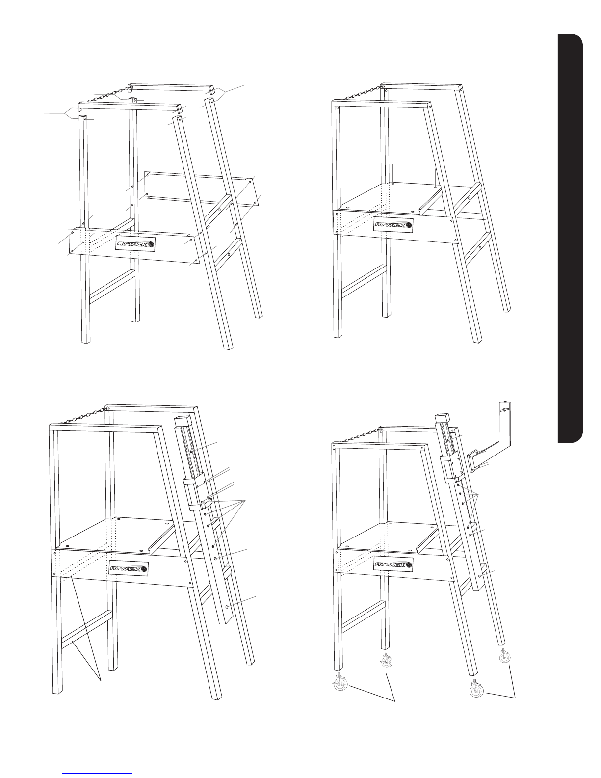
Assemble as shown in (Figure 1) using BS1 and BS1A.
9
/
16
” wrenches or two small crescent wrenches.
CAUTION
PERSONAL INJURY
HAZARD
Failure to use the special tool
provided to install the casters
could result in personal injury.
EQUIPMENT DAMAGE
Failure to use the special tool
provided to install the casters
could result in equipment damage.
Attack & AttackII Assembly Instructions
STEP THREE
With bolts from Step Two still loose, set platform in place and tighten bolts securely using
BS2. Now go back and tighten bolts from Step Two assembly (Figure 2).
STEP FOUR
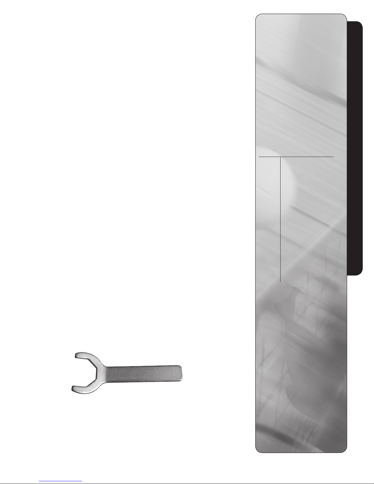
Screw casters BS3A & BS3 into the bottom of each leg (Figure 4) using wrench provided.
TIGTHEN SECURELY.
STEP FIVE
Bolt mast to frame assembly as shown in (Figure 3). Do not tighten bolts until both are in
place with the nuts on finger tight. Use bolt arrangement BS4 shown.
STEP SIX
Bolt arm assembly onto rolling tray as shown in (Figure 3). Again do not tighten bolts until all
four are in place. Use bolt arrangement BS2 shown.
STEP SEVEN
Loosen side-to-side swivel handle on arm assembly and attach throwing head by inserting
shaft into bearing provided in arm assembly and tighten side-to-side swivel handle
(Figure 3).
Assembly is now complete and your Attack or Attack II Volleyball Machine is ready for use.
See instructions in the manual and on the decals on the machine for operating procedures
and options.
HARDWARE KIT
Item# 520-9000
Bolt
Ref. Item
1
/
20
4
16
BS2
BS1A
BS1
4
2
BS4
BS3 Wrench for Casters
BS3 Casters, 4” Non-locking
BS3A Casters, 4” Locking
4
” USS Washers
1
/
4
” Split Lock Washer
1
/
4
” Nylon Nuts w/Flange
1
/
4
1
/
4
1
/
4
3
/
8
3
/
8
3
/
8
3
/
” - 20 x
4
” Bolts
” - 20 x 2” Bolts
1
/
” - 20 x 2
4
” Bolts
” USS Washers
” Nylon Nuts
” - 16 x 4” Bolts
Wrench provided (in the nut and bolt kit
with casters) to securely tighten casters.
See Page 6.
ATTACK™ AND ATTACKII™ VOLLEYBALL MACHINE
SPORTS ATTACK, LLC. • 800-717-4251 • sportsattack.com
4
Page 7
ATTACK & ATTACKII FIGURES IN ASSEMBLY
Figure 1 Using BS1 & BS1A
BS1
BS1A
BS1A
BS1
Figure 2 Using BS2
Attack & AttackII Figures In Assembly
BS2
Figure 3 Using BS4 and BS5
Position hole
BS2
BS2
Position hole
BS4
BS4
Figure 4 Using BS4, BS3 & BS3A casters
Position
hole
BS2
BS2
Position hole
BS4
BS4
Rear cross bars
Note: Attack has 2 rear cross bars
and AttackII has 1 cross bar
ATTACK™ AND ATTACKII™ VOLLEYBALL MACHINE
SPORTS ATTACK, LLC. • 800-717-4251 • sportsattack.com
BS3A
Two locking casters. Tighten
using the wrench provided.
BS3
Two regular casters
5
Page 8
COMPONENT PARTS ATTACK
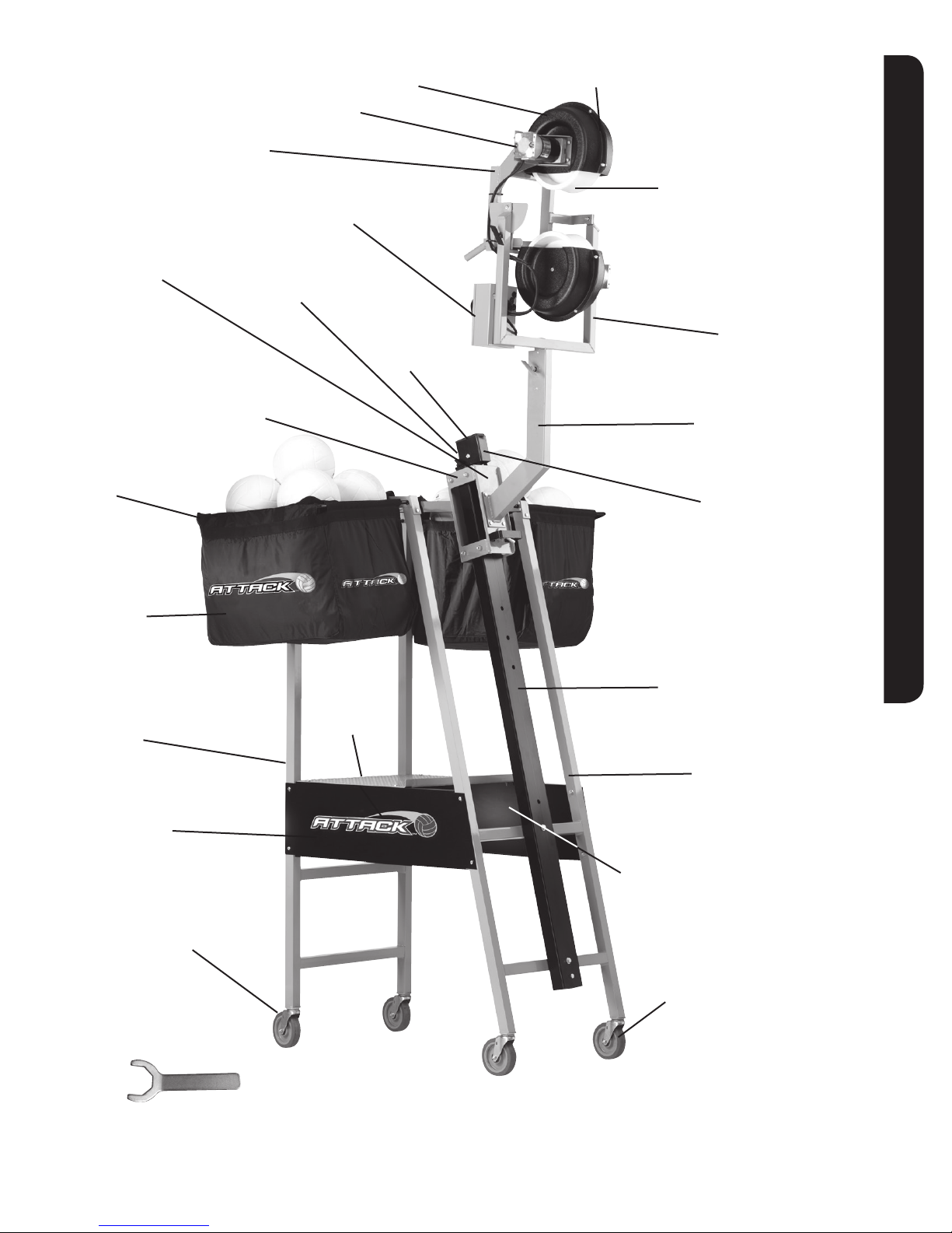
10- Motor
90V - #530-1015
180V - #530-1016
3- Throwing Head Frame
#533-4010
5- Controller
#530-0008
2- Wheel Guard Inside
#280-4001
1- Wheel Guard Outside
#280-4002
4- Throwing Wheel
#531-0007
Attack Component Parts
22- Rolling Tray Assembly
#533-4005
6- Rolling Tray Rollers
(Top & Bottom - not shown)
#271-0031 (each)
12- Ball Bag Frame
#533-4015
13- Ball Bag
(bag only)
#120-3001
14- Rear Frame Assembly
#533-4012
21- Cord Roller
(not shown)
#271-0032
20- Platform
#533-4014
19- Mast Cap
#280-7010
11- Yoke Assembly
#520-0034
8- Arm Assembly
#533-4016
9- Shock Absorber Cord
(not shown)
#680-7002
7- Mast Assembly
(includes shock absorber cord)
#520-0036
16R- Right-hand Side Panel
#533-4000
17- Locking Castor
#281-0005
18- Castor Wrench
#680-7000
15- Front Frame Assembly
16L- Left-hand Side Panel
#533-4001
23- Non-Locking Castor
#281-0004
ATTACK™ AND ATTACKII™ VOLLEYBALL MACHINE
SPORTS ATTACK, LLC. • 800-717-4251 • sportsattack.com
#533-4011
6
Page 9
ATTACK PARTS LIST
ATTACK™
EM PART NO. DESCRIPTION QTY PER
1 A-104 Rear Frame Assembly 1
2 A-105 Front Frame Assembly 1
3 533-4014 Platform 1
4 533-4000 Righthand Panel 1
533-4001 Lefthand Panel 1
5 533-4013 Top Cross Tube Assembly 2
6 281-0004 Caster, non-locking 2
281-0005 Caster, locking 2
7 531-3006 Arm Assembly 1
8 533-4002 Yoke (Universal) 1
9 520-9000 Hardware Kit 1
To order additional parts,
please contact:
Sports Attack
Customer Service Dept.
Ph 800-717-4251
Fx 775-345-2883
Attack Parts List
10 A-1A Caster Wrench 1
11 210-0003 Motor 2
12 280-0006 Throwing Wheel 2
13 223-0009 Controller 1
14 A-116 Head Assembly (Universal) 1
15 A-107 Mast Assembly (Universal) 1
16 A-115 Tray Assembly (Universal) 1
OPTIONAL ACCESSORIES
EM PART NO. DESCRIPTION QTY PER
120-3000 Ball Bag Kit (bag and frame) 1
120-3001 Ball Bag (only) 1
533-4015 Ball Bag Frame (only) 1
120-3002 Machine Cover 1
ATTACK™ AND ATTACKII™ VOLLEYBALL MACHINE
SPORTS ATTACK, LLC. • 800-717-4251 • sportsattack.com
7
Page 10
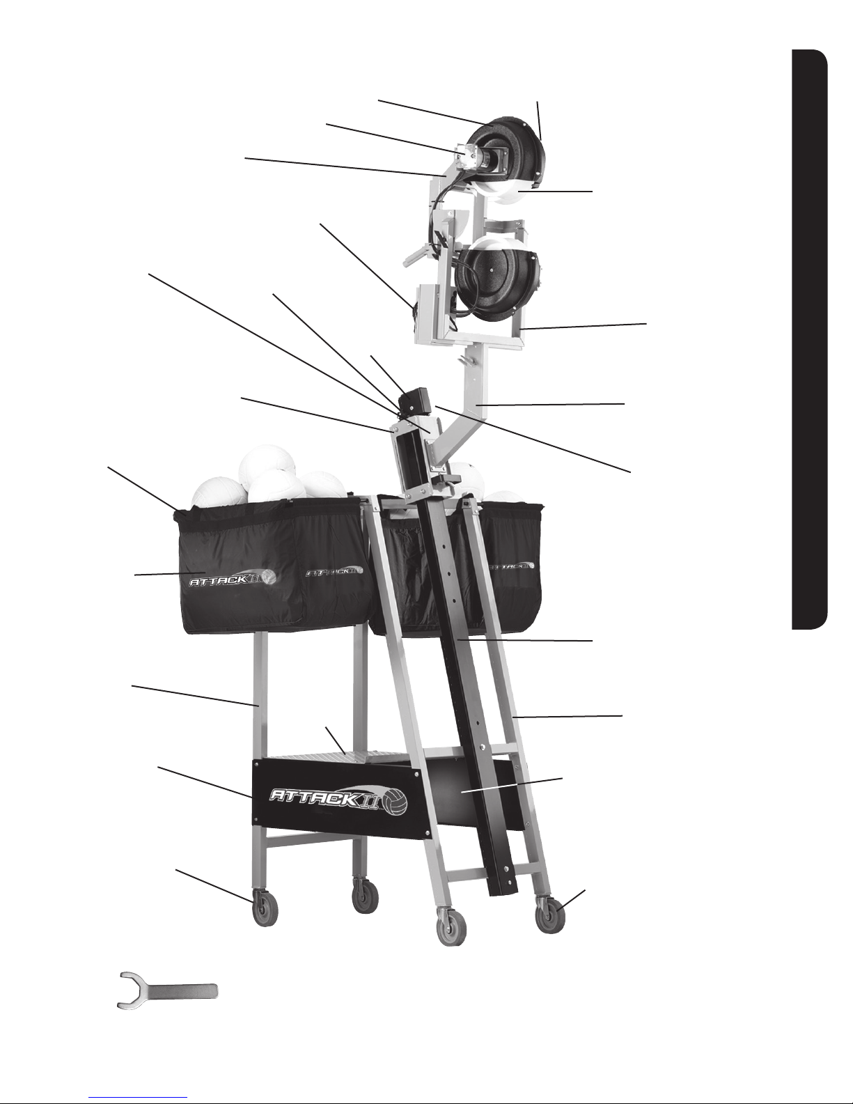
COMPONENT PARTS ATTACK II
3- Throwing Head Frame
#533-4010
22- Rolling Tray Assembly
#533-4005
6- Rolling Tray Rollers
(not shown)
#271-0031 (each)
12- Ball Bag Frame
#533-4015
10- Motor
90V - #530-1015
180V - #530-1016
5- Controller
#530-0012
21- Cord Roller
(not shown)
#271-0032
2- Wheel Guard Inside
#280-4001
19- Mast Cap
#280-7010
1- Wheel Guard Outside
#280-4002
4- Throwing Wheel
#531-0007
11- Yoke Assembly
#520-0034
8- Arm Assembly
#523-4046
9- Shock Absorber Cord
(not shown)
#680-7002
AttackII Component Parts
13- Ball Bag
(bag only)
#120-3001
14- Rear Frame Assembly
#533-4018
16R- Right-hand Side Panel
#533-4000
17- Locking Castor
#281-0005
18- Castor Wrench
#680-7000
20- Platform
#533-4014
7- Mast Assembly
(includes shock absorber cord)
#520-0036
15- Front Frame Assembly
#533-4017
16L- Left-hand Side Panel
#533-4011
23- Non-Locking Castor
#281-0004
ATTACK™ AND ATTACKII™ VOLLEYBALL MACHINE
SPORTS ATTACK, LLC. • 800-717-4251 • sportsattack.com
8
Page 11
ATTACKII PARTS LIST
ATTACKII™
EM PART NO. DESCRIPTION QTY PER
1 A2-103 Rear Frame Assembly 1
2 A2-105 Front Frame Assembly 1
3 A2-9 Platform 1
To order additional parts,
please contact:
Sports Attack
Customer Service Dept.
Ph 800-717-4251
Fx 775-345-2883
4 533-4000 Righthand Panel 1
533-4001 Lefthand Panel 1
5 A2-102 Top Cross Tube Assembly 2
6 281-0004 Caster, non-locking 2
281-0005 Caster, locking 2
8 A2-112 Arm Assembly 1
9 A2-101 Yoke (Universal) 1
10 520-9000 Hardware Kit 1
11 A2-1A Caster Wrench 1
12 A2-44 Motor 2
13 A2-2U Throwing Wheel 2
14 A2-32C Controller 1
15 A2-116 Head Assembly (Universal) 1
16 A2-107 Mast Assembly (Universal) 1
AttackII Parts List
17 A2-115 Tray Assembly (Universal) 1
OPTIONAL ACCESSORIES
EM PART NO. DESCRIPTION QTY PER
120-3000 Ball Bag Kit (bag and frame) 1
120-3001 Ball Bag (only) 1
533-4015 Ball Bag Frame (only) 1
120-3002 Machine Cover 1
ATTACK™ AND ATTACKII™ VOLLEYBALL MACHINE
SPORTS ATTACK, LLC. • 800-717-4251 • sportsattack.com
9
Page 12
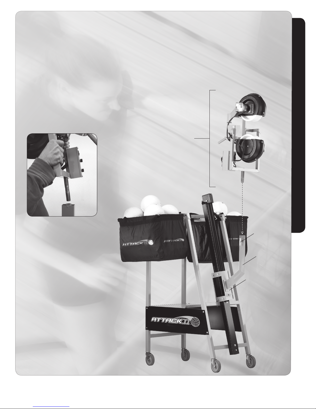
REPLACING THROWING HEAD
ATTACK and ATTACKII
STEPS IN REPLACING THE THROWING HEAD
1. Lower throwing head to the lowest position on the mast & tray
assembly. This is the “setting and transport” position.
2. Loosen side-to-side swivel handle on arm assembly.
3. Lift old throwing head assembly until it is free from
the arm assembly and set aside.
4. Lift new throwing head and insert into the bearing provided
in the arm assembly, with the throwing wheels facing away
from the mast and tray assembly. Tighten swivel handle.
Installing New Throwing Head
Throwing Head
Assembly
Swivel Handle
Arm Assembly
Mast & Tray
Assembly
ATTACK™ AND ATTACKII™ VOLLEYBALL MACHINE
SPORTS ATTACK, LLC. • 800-717-4251 • sportsattack.com
10
Page 13
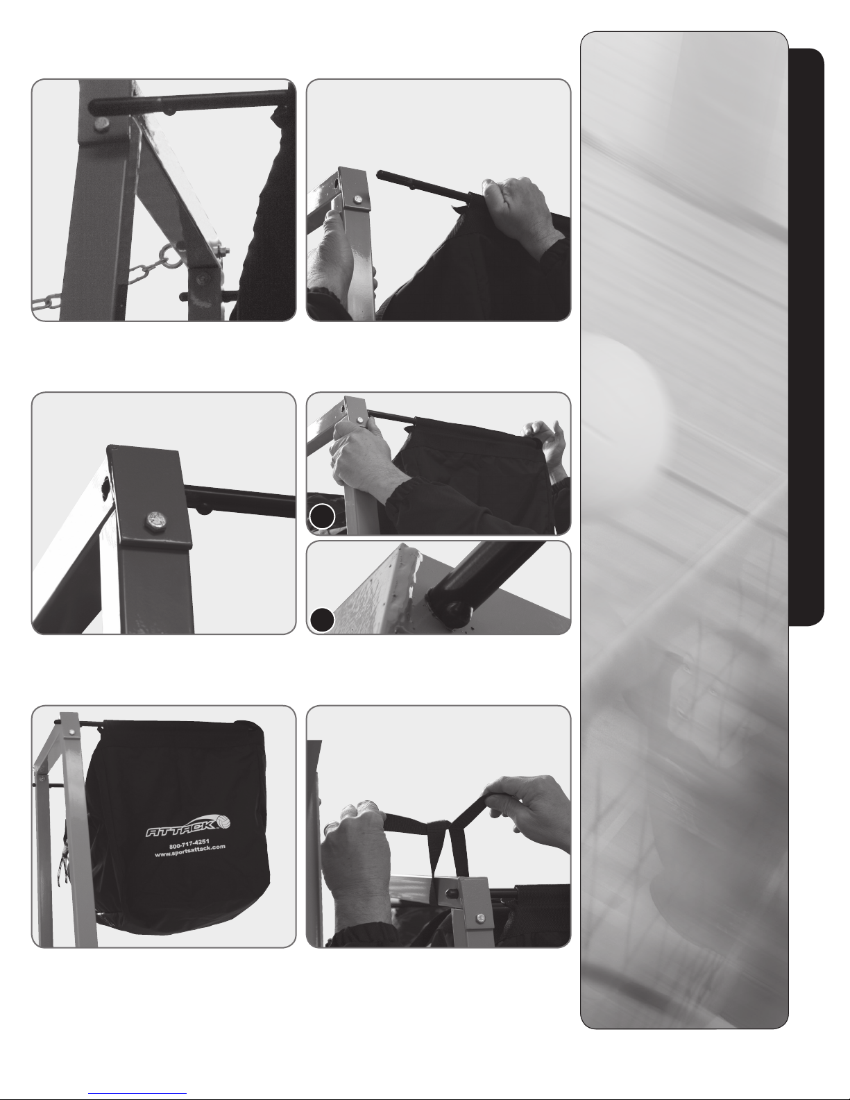
INSTALLING A BALL BAG
Step 1 Insert one arm of the ball bag frame into the appropriate holes
on the platform frame.
Step 2 Carefully apply firm pressure to bend the other arm so that it
lines up with the corresponding holes on the platform frame.
INSTALLING A BALL
BAG
STEP 1
Insert one arm of the ball bag
frame into the appropriate holes on
the the platform frame. The second
arm of the ball bag frame will not
line up with the set of
corresponding holes on the
platform frame. This is intentional.
STEP 2
Holding on to the platform frame
as shown in the photo for Step 2,
carefully apply firm pressure on
the second arm and bend it until
it lines up with the corresponding
holes in the platform frame.
STEP 3
Insert arm into the corresponding
holes on the platform frame.
Installing A Ball Bag
Step 3 Insert arm of ball bag frame into the holes on the
platform frame.
A
B
Step 4
A Use your palm to “whack” the ball bag frame.
B Button will rest against frame.
STEP 4 A & B
Still holding on to the platform
frame with one hand, use the
palm of your other hand to “whack”
the frame (photo A) until the
button rests against the frame
(photo B).
STEP 5
Both arms are now securely in
place with the proper amount
of tension to keep ball bag
in place.
STEP 6
To order additional parts, like
a ballbag, please contact:
Sports Attack
Customer Service Dept.
Ph 800-717-4251
Fx 775-345-2883
Step 5 Both arms are securely in place.
ATTACK™ AND ATTACKII™ VOLLEYBALL MACHINE
SPORTS ATTACK, LLC. • 800-717-4251 • sportsattack.com
Step 6 Tie ball bag straps.
11
Page 14
VOLLEYBALL OPERATION
The Attack or AttackII is a total practice machine. No special training other than the
complete, careful reading of this manual is required to operate the machine. Many
coaches have broadened and refined their own coaching skills by its use.
ELEVATING AND LOWERING THE MACHINE HEAD
1. Release the locating pin on the sliding tray.
2. Position the throwing head into one of five elevation settings to the required height.
3. Locating pin will snap into place.
INCREASE OR DECREASE SPEED
1. Before turning machine “ON,” turn dials located on the throwing head to the “0” position.
2. Turn on/off switch to “ON.” The wheels will spin slowly. Turn speed control knobs
clockwise to increase speed.
3. Turn the speed control knobs counter-clockwise to decrease speed.
BALL SPIN, BREAK OR MOVEMENT
1. Floater: Both knobs turned to the same setting, making the wheels spin at the
same RPM.
2. Top Spin: Upper wheel turning fast, lower wheel turning slowly. Variations of the ball
spin and break are determined by the wheel speeds.
HORIZONTAL CONTROL
1. Loosen to vary direction.
2. Tighten for repeatability.
Attack & AttackII Operation
ATTACK™ AND ATTACKII™ VOLLEYBALL MACHINE
SPORTS ATTACK, LLC. • 800-717-4251 • sportsattack.com
12
Page 15
VOLLEYBALL SHUTTING DOWN
TURNING ATTACK “OFF”
1. Set each speed control dial to “0.”
2. Turn the on/off switch “OFF.”
3. Unplug Attack or Attack II from the power source.
TRANSPORTING
1. Turn the machine “OFF” and unplug.
2. Lower throwing head to the lowest position on the sliding tray. The locating pin
will snap into place.
DO NOT STORE OR TRANSPORT WITH THROWING HEAD ELEVATED.
Attack & AttackII Shutting Down
ATTACK™ AND ATTACKII™ VOLLEYBALL MACHINE
SPORTS ATTACK, LLC. • 800-717-4251 • sportsattack.com
13
Page 16
CARE, CLEANING & MAINTENANCE
LUBRICATION
Throwing Wheel Motors
Motors are sealed and require no lubrication.
CLEANING THE THROWING WHEELS
The throwing wheels must be kept clean to maintain accuracy. Clean the wheels periodically
to control the build-up of dirt.
1. Turn the on/off switch “OFF” and allow the wheels to come to a complete stop. Unplug
machine from electric power.
Dampen a rag with soap and water. Turn the throwing wheel by hand and scrub the wheel
until the build-up is removed. For very heavy build-up, a synthetic scouring pad, such as a
Scotch-Brite
Ketone (M.E.K.) may be required to help loosen the build-up of dirt or ball residue.
EXAMINE THE MACHINE
Examine Attack or AttackII for condition and completeness before every use:
® scouring pad, or medium sandpaper may be used sparingly. Methyl Ethyl
CAUTION
PERSONAL INJURY
HAZARD
Never attempt to clean the
throwing wheels while they are
turning. Rags or implements
caught in spinning wheels can
cause serious injury.
Unplug machine before cleaning
the wheels or performing any
kind of service.
CHEMICAL HAZARD
Methyl Ethyl Ketone (M.E.K)
Read and follow the directions
and safety instructions on the
M.E.K container.
Care, Cleaning & Maintenance
1. Throwing wheels must be tight on the motor shafts. Check that the keyway retaining
bolts are tight.
2. Wheel guard must be securely fastened to the throwing head.
3. Check rolling casters once a year for tightness. Tighten bolts securely using wrench
provided, but do not over-tighten. See Page 8, Schedule 3.
4. Check all casters and bolts of frame once a year for tightness.
FIRE HAZARD
Methyl Ethyl Ketone (M.E.K)
M.E.K. is flammable. Do not
use M.E.K. around a fire or
flame. Do not use M.E.K. near
a running generator or other
ATTACK™ AND ATTACKII™ VOLLEYBALL MACHINE
SPORTS ATTACK, LLC. • 800-717-4251 • sportsattack.com
14
Page 17
COMPONENT REPLACEMENT
THROWING WHEEL REPLACEMENT
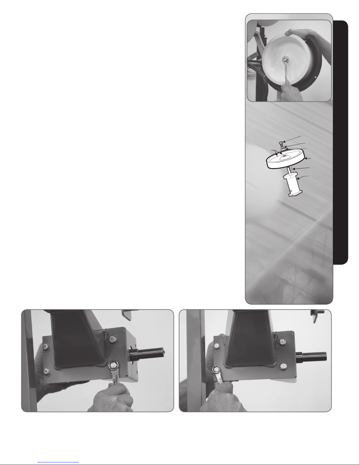
1. Turn the throwing wheels “OFF” and unplug the power cord. Remove four bolts
holding the wheel guard to the motor-side wheel guard.
2. Hold the wheel so that it cannot move. Turn the keyway retaining bolt counter-clockwise
using a box end wrench (See Figure 9).
SUGGESTION: If the bolt is too tight, give the opposite end of the wrench a series of
light taps with a hammer making sure the wrench remains on the bolt.
3. Remove the bolt and washers.
4. Work the wheel off of the motor shaft. Be sure to catch the key as it is freed from
the keyway.
5. Ball throwing wheels are machine balanced. Small holes in the side of the wheel are
applied at the factory and are normal. A slight wobble is also normal.
Component Replacement
Figure 9 Hold wheel while loosening bolts.
Reassemble in reverse order.
a. Install wheel to motor shaft with key slots aligned.
b. Be sure the key is in place, and inserted so that it is flush with the boss at the
wheel center.
c. Be sure the washer and lock washer are installed in the right order, and that the
keyway retaining bolt is tightened.
d. Test the wheel by spinning it by hand and making sure that it spins freely before
turning the unit “ON”.
e. Be sure the wheel guard is properly and securely reinstalled.
NOTE: Check bolts for tightness once a season. Tighten bolts securely, but do
not over-tighten.
MOTOR REPLACEMENT
1. Turn the on/off switch “OFF” and unplug the power cord.
2. Remove the throwing wheel (see above) and two wheel guards.
3. Remove four screws holding controller into main electrical box. Note the position of
the motor wires on the controller, then disconnect the wires. See Page 14.
4. Note the routing of the motor wires. Loosen any wire clamps.
5. Remove bolts holding the motor to the main frame.
Reassemble in reverse order.
HOLES DRILLED
FOR BALANCE
1/2” KEYWAY
RETAINING BOLT
LOCK WASHER
FL AT WASHER
THROWING
WHEEL
KEY
MOTOR
Figure 10 Shown using a 6” 1/2” wrench. Figure 11 Shown using a 1/16” wrench.
NOTE: Check bolts for tightness once a season. Tighten bolts securely, but do not over-tighten.
ATTACK™ AND ATTACKII™ VOLLEYBALL MACHINE
SPORTS ATTACK, LLC. • 800-717-4251 • sportsattack.com
15
Page 18
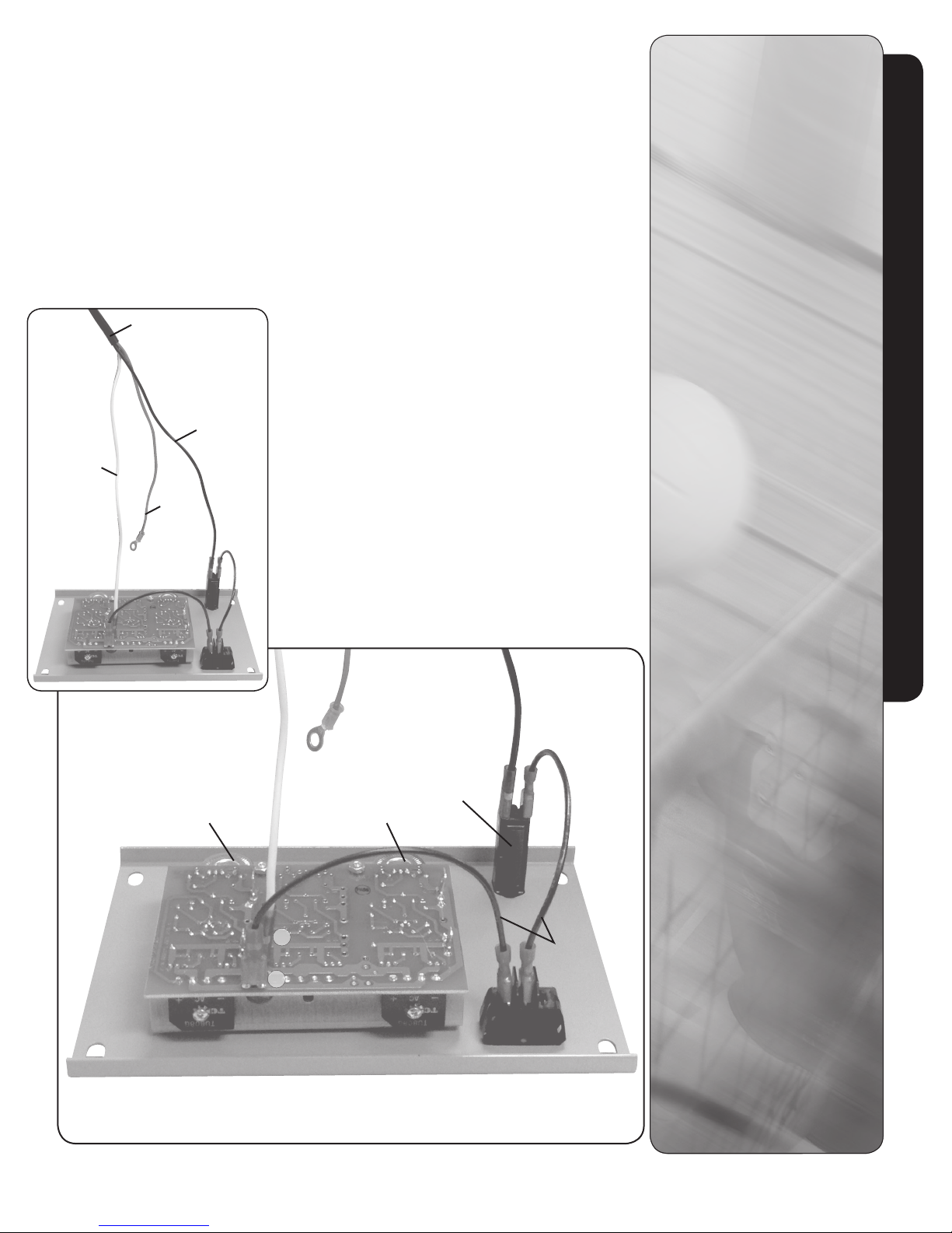
COMPONENT REPLACEMENT (cont’d)
CONTROLLER REPLACEMENT
1. Turn the on/off switch “OFF” and unplug the power cord.
2. Remove the four screws holding controller faceplate. Note the position of the main
power and motor wires on the controller, then disconnect the wires.
Reassemble in reverse order.
a. Be sure wires are correctly reinstalled. Motor wire connectors are different sizes.
Be sure they are installed on the correct size terminal.
b. When attaching the knobs, turn the speed control shafts fully counter-clockwise,
then install the knobs with the pointer to “0.”
Power Cord
Black/
Brown
White/
Blue
Green
(Ground)
WIRING
POWER CORD
White or Blue Wire (1)
To middle male terminal
marked “N.”
Black or Brown Wire (2)
To circuit breaker.
Green Wire (3)
Grounds to machine/motor.
MOTOR WIRE LEADS
White 3/16” wide connectors.
Black 1/4” wide connectors.
Black Wire (2) connects to A-
on circuit board.
White Wire (2) connects to A+
on circuit board.
CONTROLLER
Black Wire (2)
2 PR jumper wire:
- 1 from on/off switch to
circuit breaker
- 1 from on/off switch to
circuit board terminal “L”.
Component Replacement
Bottom Motor
Black (A-) 1/4”
White (A+) 3/16”
Top Motor
Black (A-) 1/4”
White (A+) 3/16”
N
L
ATTACK™ AND ATTACKII™ VOLLEYBALL MACHINE
SPORTS ATTACK, LLC. • 800-717-4251 • sportsattack.com
Circuit
Breaker
Black
Jumper
Wires
16
Page 19
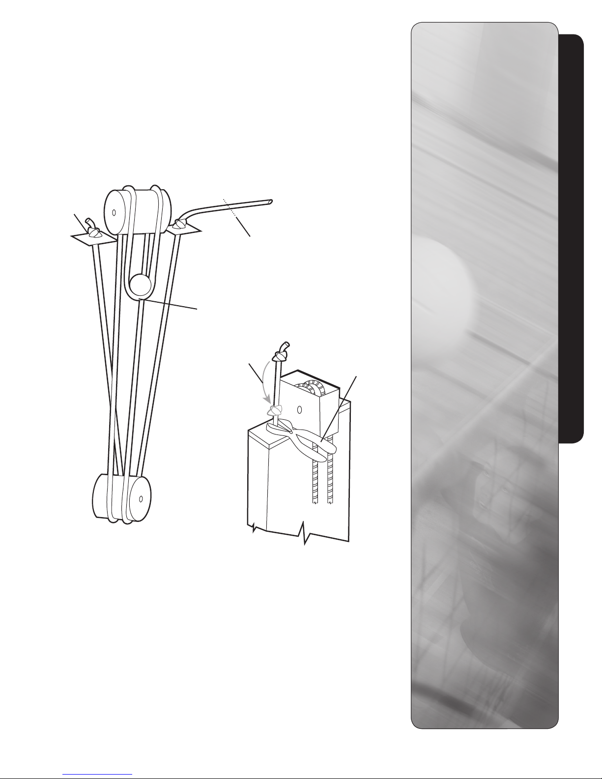
INCREASING TENSION INSTRUCTIONS
STEPS IN INCREASING TENSION ON THROWING HEAD (LO
CATED AT A)
1. Stretch cord approzimately 12” (this distance can be adjusted as required)
2. Using vise grips as shown, clamp tightly to hold shock absorber cord.
3. Loosen knot and slide it down to top of vise grips.
4. Repeat process on opposite side.
A
Start here.
Middle mark on rope
must end up here!
Slide knot down to
top of vise grips.
Increasing Tension Instructions
After you have tied off
the cord, cut off at the
mark here.
Vise grips.
ATTACK™ AND ATTACKII™ VOLLEYBALL MACHINE
SPORTS ATTACK, LLC. • 800-717-4251 • sportsattack.com
17
Page 20
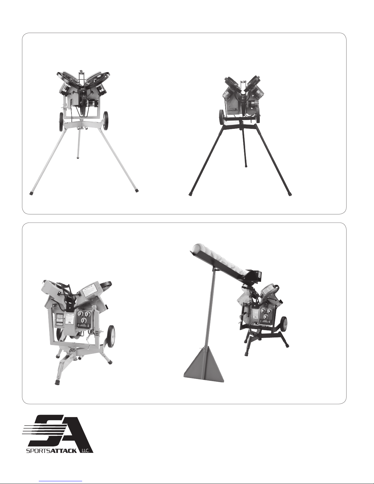
SPORTS ATTACK PRODUCTS
BASEBALL
HACK ATTACK BASEBALL
SOFTBALL
JUNIOR HACK ATTACK BASEBALL
HACK ATTACK SOFTBALL
Please visit our web site sportsattack.com for information about Sports Attack sports
training products, or call 800-717-4251 for complete information and specifications.
ATTACK™ AND ATTACKII™ VOLLEYBALL MACHINE
SPORTS ATTACK, LLC. • 800-717-4251 • sportsattack.com
JUNIOR HACK ATTACK SOFTBALL (shown with optional solo feeder)
18
Page 21
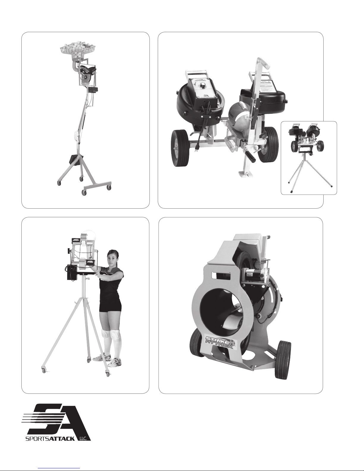
SPORTS ATTACK PRODUCTS
TENNIS FOOTBALL
ACE ATTACK SNAP ATTACK
VOLLEYBALL
SOCCER
SKILL ATTACK
Please visit our web site sportsattack.com for information about Sports Attack sports
training products, or call 800-717-4251 for complete information and specifications.
ATTACK™ AND ATTACKII™ VOLLEYBALL MACHINE
SPORTS ATTACK, LLC. • 800-717-4251 • sportsattack.com
STRIKE ATTACK
19
 Loading...