

SportsArt Fitness XT20 Fitness Owner's Manual
XT20

SPORTS ART COMMERCIAL GRADE XT20
X-TRAINER
TABLE OF CONTENTS
A. SAFETY GUIDELINES .......................................................................................
B. INTRODUCTION.................................................................................................
C. ASSEMBLING YOUR X-TRAINER
List of parts..........................................................................................................
Step by step instructions......................................................................................
D. UNDERSTANDING THE XT20 DISPLAY CONSOLE
Windows...............................................................................................................
Keypad.................................................................................................................
E. OPERATING YOUR X-TRAINER
Power Up the X-Trainer........................................................................................
Quick Start............................................................................................................
Entering User's Personal Information...................................................................
Power Standby Mode...........................................................................................
Turn Off the X-Trainer...........................................................................................
F. OVERVIEW OF PROGRAMS
Manual Mode........................................................................................................
Random................................................................................................................
WT Loss (HRC 65%) / CARDIO (HRC 80%).......................................................
Conditioning and Advanced Conditioning............................................................
Cool Down............................................................................................................
Stop......................................................................................................................
Displaying Workout Data......................................................................................
G. SYSTEM DEFAULT SETTING
Setting Modify......................................................................................................
Setting Weight Units.............................................................................................
H. RANGES OF VARIOUS SETTINGS....................................................................
I. SETTING RANGES..............................................................................................
J. MAINTAINING THE X-TRAINER..........................................................................
K. GUIDELINES FOR EXERCISE
How long should I exercise?................................................................................
How often should I exercise?...............................................................................
L. TROUBLESHOOTING
Load response issues..........................................................................................
Appendix: Wiring Schematic................................................................................
1
2
3
4
10
11
13
13
14
15
15
16
17
18
19
20
21
22
23
23
23
24
24
24
24
25
26

A. SAFETY GUIDELINES:
Please read and follow the following safety guidelines:
Keep this owner's manual for future use and reference.
Read this owner's manual and follow the instructions.
Assemble and operate the SportsArt XT20 Trainer on a solid, level surface.
Never allow children on or near the machine.
Check the machine before every use. Make sure all parts are assembled; all nuts
and bolts are tightened. Do not use the machine if the unit is disassembled in any
way.
Keep your hands away from moving parts.
Wear proper workout clothing. Do NOT wear loose clothing. Do not wear shoes
with leather soles or high heels. Tie back all long hair.
Don't rock the unit from side to side; take care when mounting and dismounting
the unit.
Do not use any accessories that aren't specifically recommended by the
manufacturer as these might cause injuries or cause the unit to fail.
Work within your recommended exercise level. Do NOT work to exhaustion.
If you feel any pain or abnormal sensations, STOP YOUR WORKOUT.
Consult your physician immediately.
Allow sufficient space on both sides of the trainer for users to mount and dismount
the machine.
If any parts fail or are defective, please stop your workout immediately and contact
your authorized dealer for repairs.
1

2
B. INTRODUCTION
Congratulations on purchasing one of the finest pieces of commercial grade exercise
equipment in the market today, the SportsArt XT20. Constructed of high quality
materials and designed for years of trouble free usage, the XT20 will be an integral
part of your fitness regimen.
Before using your trainer, we recommend that you familiarize yourself with this
Owner's Manual. Whether you are a first time user of an X-trainer or a seasoned
"pro," understanding the correct use of the equipment will enhance your ability to
achieve your exercise goals safely and successfully.

C. ASSEMBLING YOUR X-TRAINER
LIST OF PARTS:
1. One Display Support Tube
2. One Left Pedal
3. One Right Pedal
4. One Seat Back
5. One Seat Bottom
6. One Left Upper Body Bar
7. One Right Upper Body Bar
8. Two Upper Body Bar Inner Covers
9. Two Upper Body Bar Exterior Covers
10. Three 5/16"* L19 bolts for the Display Pedestal
11. Three 5/16"* L19 bolts for the Seat Back
12. Three 5/16*D20*t2.0 Flat Washers for the Seat Back
13. Four 5/16*L19 Bolts for the Seat Bottom
14. Four Flat Washers 5/16*D20*t2.0 for the Seat Bottom
15. Eight 5/16*L19 Bolts for Left and Right Upper Body Bars
16. Eight D18*d8.5*t2.0 Washers for Left and Right Upper Body Bars
17. Four Flat Washers D17*d8.3*t2.0 for Left and Right Upper Body Bars
18. Eight Spring Washers 5/16 *t2.0 for Left and Right Upper Body Bars
19. Eight Phillips Head Screws M4*L20 for Upper Body Bar Covers
20. One Screwdriver
21. One Hex Allen Wrench
22. One Open-ended Wrench
23. Three Fuses ( 2 AMP x 2 and 3 AMP or 3.15 AMP)
3
STEP BY STEP INSTRUCTIONS
Before assembling your X-trainer, make sure that you have all parts listed on the
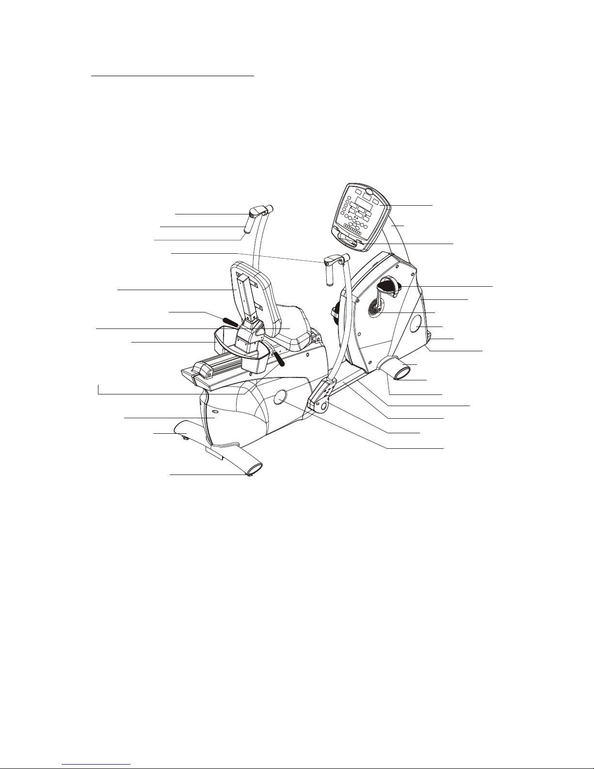
previous page. Refer to the product illustration below.
Product Illustration
4
Leg Resistance Switch
Upper Body Handle
Handlebar end cap
Arm Resistance Switch
Seat Back
Seat Adjustment Lever
Seat
Storage Tray
Rear Cover
Rear Cross Frame
Seat Back
Adjustment Lever
Magazine Tray
Pedal
Front Cover
Crank Access Cover
Front Cover Label
Electronics Package
Electronics Display Pedestal
Charger
Front Cross Frame Cover
Floor Level Adjustment
Floor Level Adjustment
Front Cross Frame
Base Frame
Base Frame Cover
Transport wheel
Upper Body Bar Covers
Rear Cover Label
The following steps explain how to assemble your SportsArt XT20. Please read
every step thoroughly. Follow the directions completely to ensure correct assembly.
1. Remove the trainer from the box and separate packing material from the trainer
parts.
2. Place all parts on a flat surface so that they can be found more easily.
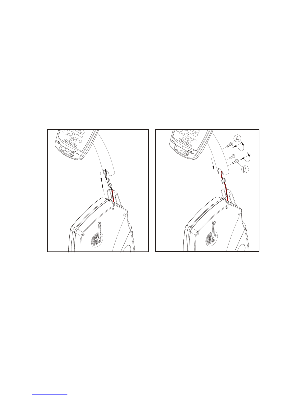
3. Connect the data cables (female to male) between the pedestal and the trainer
frame. Install the Pedestal to the trainer frame. Install the pedestal to the trainer
frame. Firstly attach the top bolt A provide, don't tighten yet. If it is a bit to insert
the bolt A into the hole, please hold the pedestal to align the bole. Then attach two
bolts B below as well, don't tighten either. Finally fasten bolt A, then bolt B
clockwise to secure them completely.
5
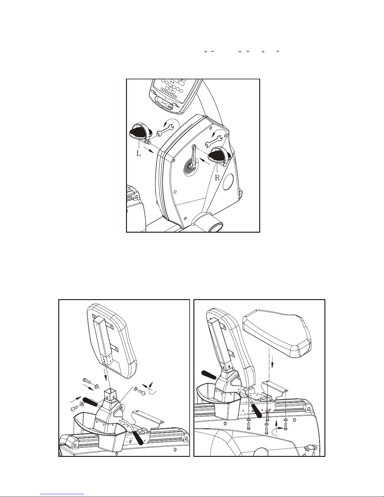
4. Install right and left Pedals to right and left crank arms respectively, using the
wrench provided. Be careful to distinguish L from R . Left is the user's
left, as he or she exercises on the equipment. After installation, rotate pedals
counterclockwise to secure them (see the following illustration).
5. Install the Seat Back onto the seat post by using the bolts and washers provided.
Make sure the bolts and washers are tightened to secure the Seat Back. Install
the seat to the handlebar mounting plate; fix the seat with the bolts and washers
provided. Secure the bolts from underneath the seat, with two bolts in front and
two in back, through the handlebar mounting plate. Tighten the bolts (see the
following illustration).
6
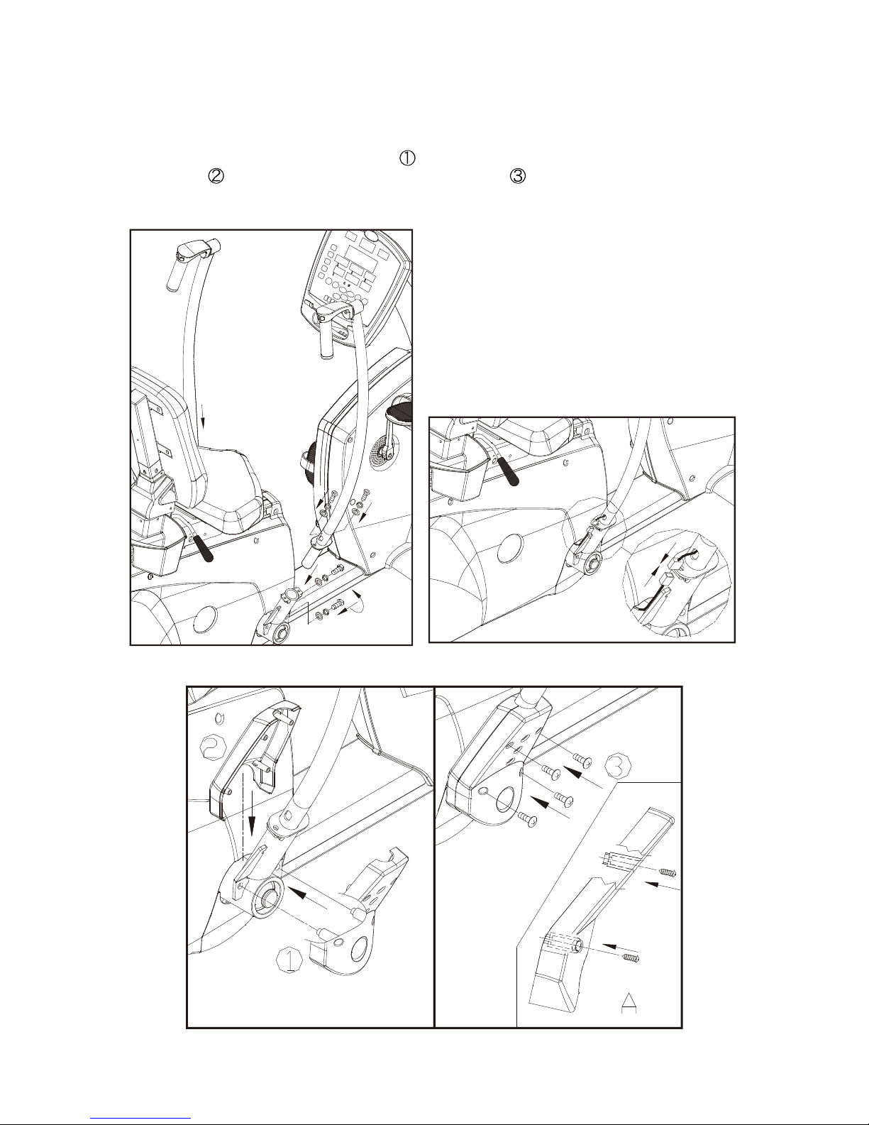
6. Insert right and left upper body bars into their respective connector tubes. Secure
the bars with the four bolts attached. Connect the wires in the upper body bars.
Attach the exterior enclosure firstly that two ribs on it go into the holes on the
bottom of upper body bars as step , then put the interior enclosure in placement
as step . Finally tighten 4 bolts provided as step . (Please fasten the top right
or left bolt firstly and keep the bolt to align the rib for easy assembly. See Fig. A)
7
 Loading...