

SportsArt Fitness XT20 Cross Trainer Repair Manual

XT20 Cross T rainer Repair Manual
SPORTSART INDUSTRIAL CO., LT D.

.
Contents
1. Component Recognition
1-1-1. XT20 Picture
1-2-1. XT20 Display
1-3-1. XT20 Lower Body (Rear)
1-3-2. XT20 Lower Body (Front)
1-4-1. XT20 Display
1-5-1. XT20 Display Board (Front)
1-5-2. XT20 Display Board (Back)
2. XT20 Functions
2-1-1. XT20 Specification Table
2-2-1. XT20 Display Window Functions
2-3-1. XT20 Display Key Functions
3. XT20 Operation
3-1-1. Battery Start Up
3-1-2. Alternator Start Up
3-1-3. Quick Start Mode
3-1-4. Operating from Quick Start Mode
3-1-5. LEG/ARM Work Level Setting
3-1-6. Start Mode
3-1-7. Operate Programs
3-1-8. Operating Programs (Cont.)
3-1-9. Stopping Programs
3-1-10. Battery Shut Off
3-1-12. Show Total Distance
3-1-13. Set KPH/MPH Mode
0-0-1
Note: XT10 and XT20 are mechanically and
electronically identical. The only difference is in
their displays. The residential model XT10 has
user programs. The commercial model XT20
does not have user programs. For general
troubleshooting, this manual applies to XT10
and XT20.
Manual updates follow:
Version 1: 12-07-05 – Initial version
Version 2: 02-01-06 – Note below added
Note: The cover picture shows a prototype with
handles (like the C5150 bike). Production units
of XT10 and XT20 never had such handles.
For comments or suggestions, please contact
bob@sportsartamerica.com.

.
Contents
4. Block Diagrams
4-1-1. XT20 Display Board Wire Connection Block Diagram
4-1-2. XT20 Drive Board Wire Connection Block Diagram
5. Connections and Components on Boards
5-1. Display Board
5-1-1. XT20 Display Board Wire Connection Block Diagram
5-1-2. XT20 Display Board Component Placement
5-1-3. XT20 Display Board LED Indicators
5-1-4. XT20 Display Board Wire Connectors
5-2. Drive Board
5-2-1. XT20 Drive Board Wire Connection Block Diagram
5-2-2. XT20 Drive Board Component Placement
5-2-3. XT20 Drive Board LED Indicator Placement and Definitions
5-2-4. XT20 Drive Board Wire Connectors
5-2-5. XT20 Drive Board Fuse Locations
0-0-2

Contents
6. Error Messages
6-1-1. Unit Does Not Start when Keys Are Pressed. (Continued on 6-1-2.)
6-2-1. Move the Pedals or Arms; The Display Does Not Light. (Continued on 6-2-2.)
6-3-1. Move the Pedals or Arms; The Display Leg or Arm RPM Window Shows 0. (Cont. 6-3-2.)
6-4-1. There is No Resistance on Arms or Legs. (Continued on 6-4-2.)
6-5-1. Remote Key Malfunction (Continued on 6-5-2.)
6-6-1. The Battery Does Not Recharge (Continued on 6-6-2.)
6-7-1. Polar Heart Rate Malfunction (Continued on 6-7-2.)
7. Electronic Component Testing
7-1-1. XT20 Alternator Test (Continued on 7-1-2.)
7-2-1. XT20 Battery Voltage Test
7-3-1. XT20 Electro-Magnet Test
7-4-1. XT20 Reed Switch Test (Continued on 7-4-2.)
7-5-1. XT20 Alternator Power Test at the Drive Board (Continued on 7-5-2.)
7-6-1. XT20 Battery Test at the Drive Board (Continued on 7-6-2.)
7-7-1. XT20 Resistance Voltage Test at the Drive Board (Continued through 7-7-3.)
7-8-1. XT20 VCC Voltage Test at the Drive Board (Continued on 7-8-2.)
7-9-1. XT20 VCC Voltage Test at the Display Board (Continued on 7-9-2.)
7-10-1. XT20 Display Board Key Test
7-11-1. XT20 Arm Remote Key Test (Continued on 7-11-2.)
7-12-1. XT20 Polar Heart Rate Test (Continued on 7-12-2.)
7-13-1. Addendum: XT20 Drive Board Overview; Voltage Specifications (7-13-2)
0-0-3

.
XT20 Picture
1-1-1

.
XT20 Display
1-2-1
.
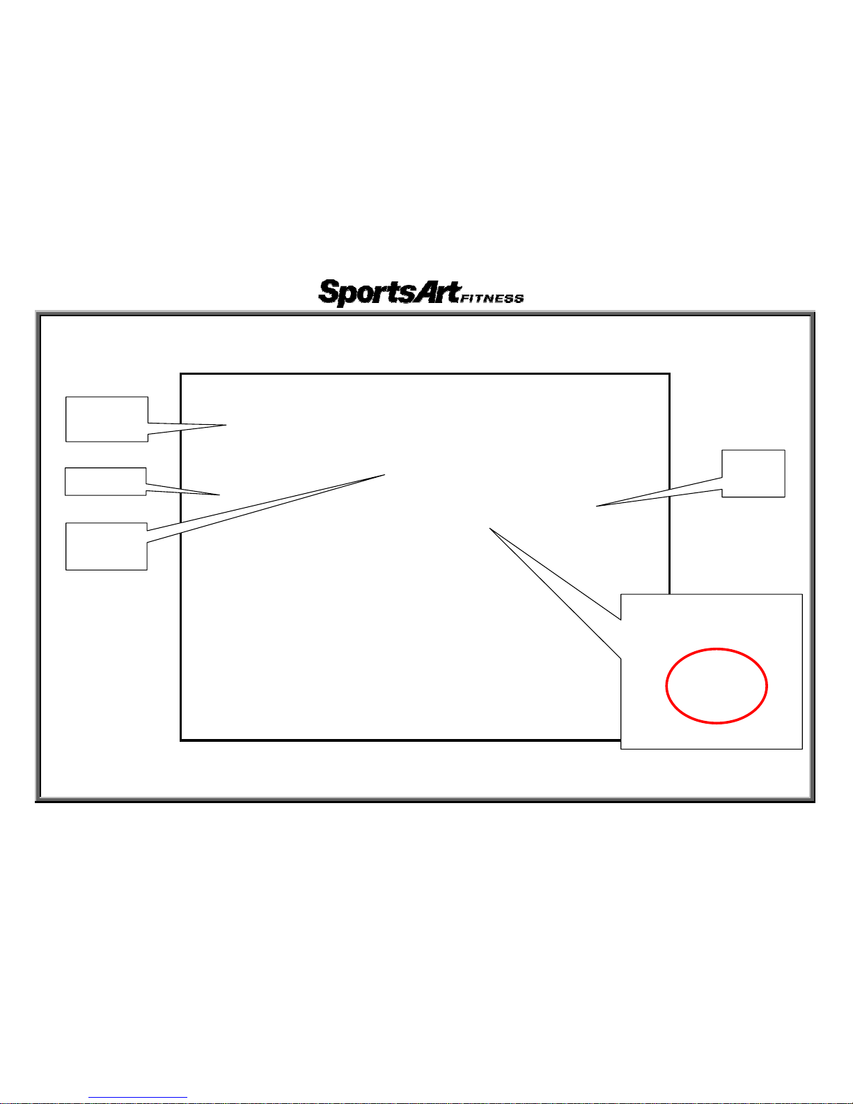
XT20 Lower Body (Rear)
1-3-1
Flywheel
Drive
board
Electromagnet
AC
alternator
Reed switch and magnet
.
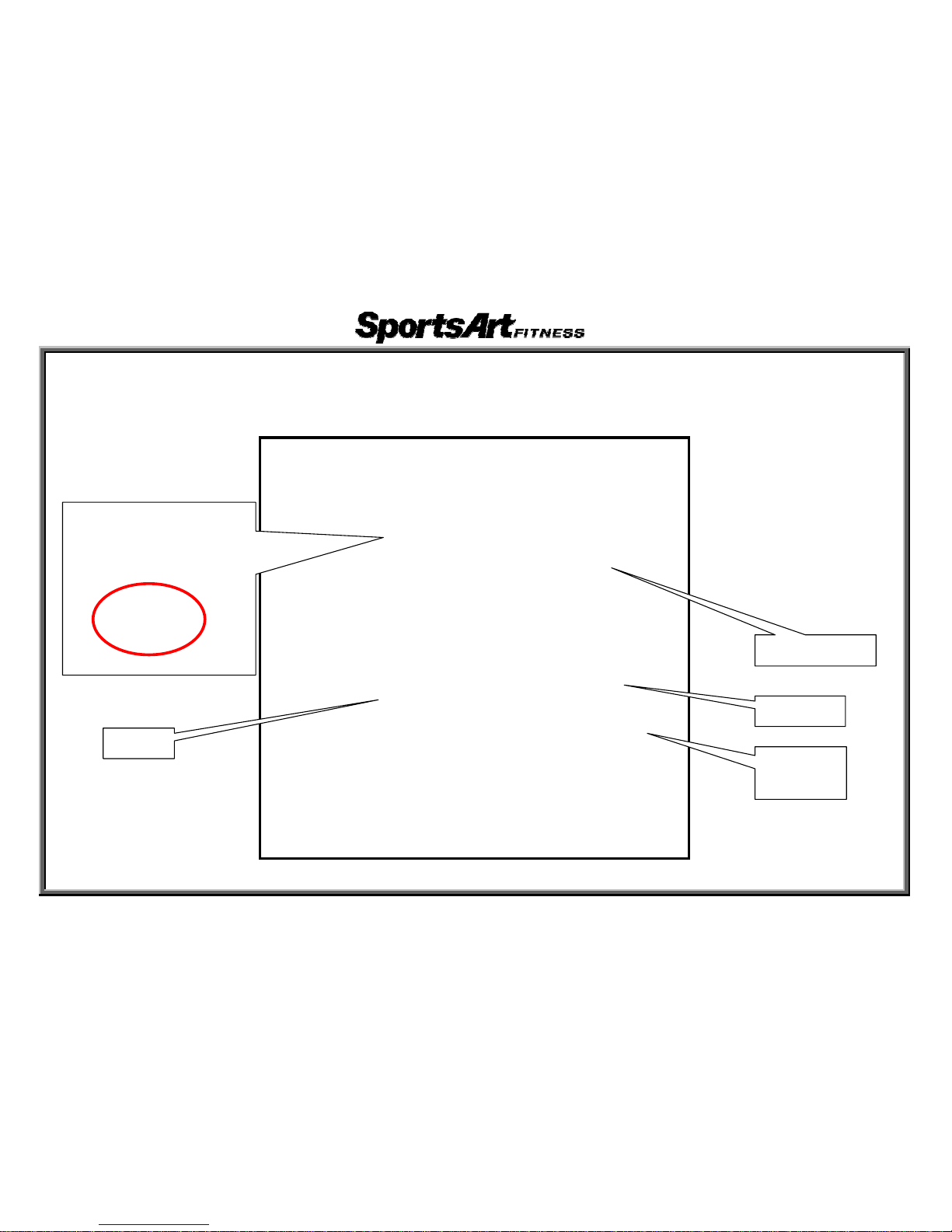
XT20 Lower Body (Front)
1-3-2
AC alternator
Flywheel
Electromagnet
Battery
Reed switch

XT20 Display
1-4-1

XT20 Display Board (Front)
1-5-1

XT20 Display Board (Back)
1-5-2

XT20 Specification Table
Function Specifics Model
Heart rate
Telemetry heart rate
65% HR target
80% HR target
XT20
Main window
Moving prompts or illustrations
Dot matrix 5*5*8 LED two-color dot matrix (red/green)
XT20
Mode window
Work Lever(LEG)/ Work Lever(ARM)
CALORIES / CAL / HR / DISTANCEMETS / WATTS
LEG RPM / TIME / ARM RPM
XT20
Program window
MANUAL / RANDOM / CARDIO / WT LOSS /
CONDITONING / ADVANCED CONDITONING
XT20
Heart rate detection POLAR wireless telemetry heart rate XT20
Key Key/ toggle switch XT20
Work level
Work level(LEG)1~20
Work level(ARM)1~20
XT20
Power Hand/leg independent power generation XT20
Backup Power Rechargeable battery (hand/leg independent batteries) XT20
Resistance
Leg: electro-magnetic (belt drive)
Arm: electro-magnetic (chain drive)
XT20
Seat
Adjustable back
Adjustable seat
XT20
Electronic Specifications
Rechargeable battery: 6.4 V
Alternator: AC brushless
Resistance voltage – arm: 2.0~10.2V
Resistance voltage – leg: 2.7~17.2V
XT20
2-1-1
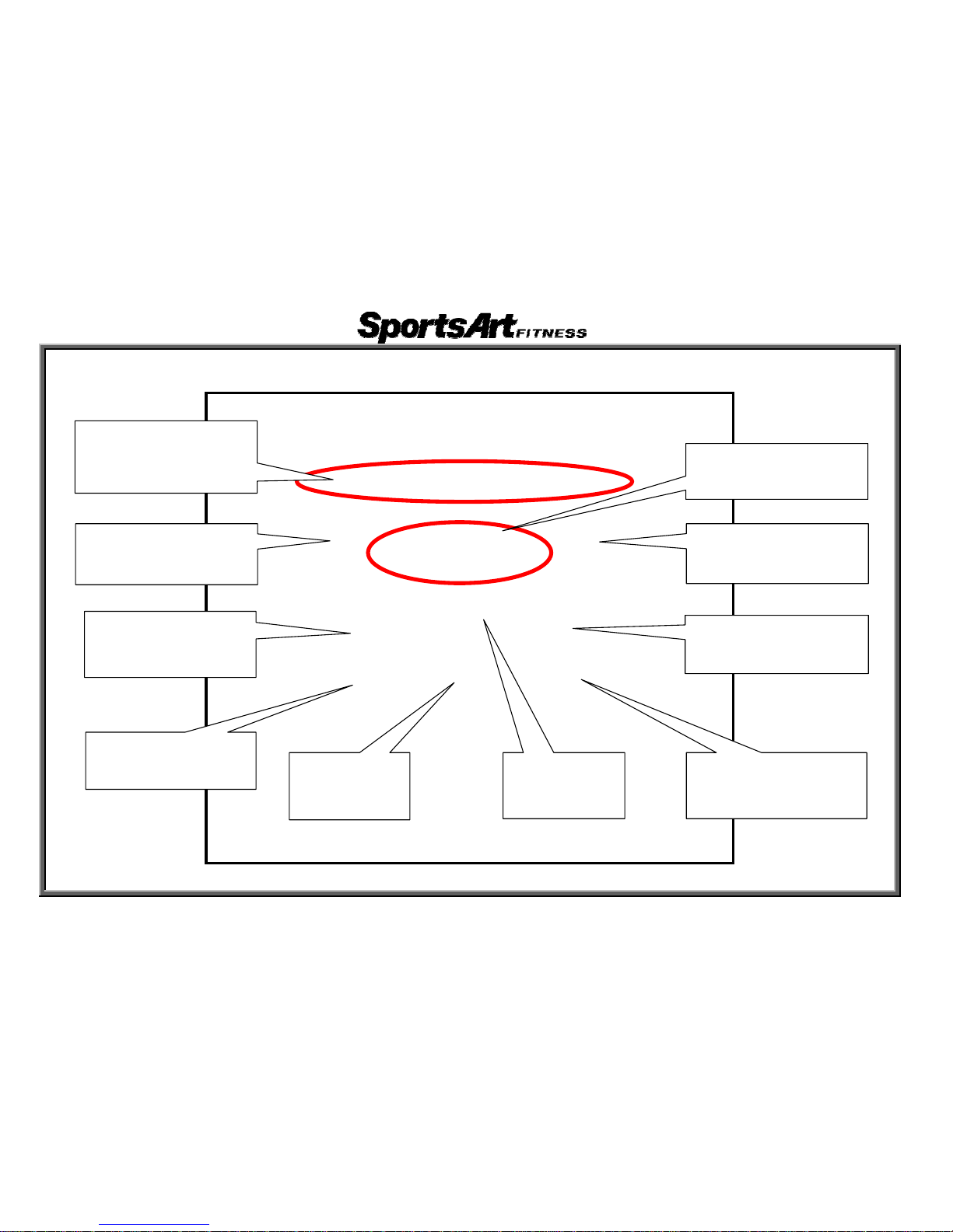
XT20 Display Window Functions
2-2-1
Arm work level
ÎShows arm resistance
level
METS
ÎShows METS and
WATTS values
Heart rate
ÎShows 65% HR target
ÎShows actual heart rate
ÎShows 80% HR target
Main window
ÎShows prompts and
illustrations
Leg work level
ÎShows leg resistance
level value
Leg RPM
Î Shows rotations per
minute (leg)
Arm RPM
ÎShows rotations per
minute
(
arm
)
Time
ÎShows time
Distance
ÎShows
distance
Calorie
ÎShows calorie burn
and calorie burn per hour
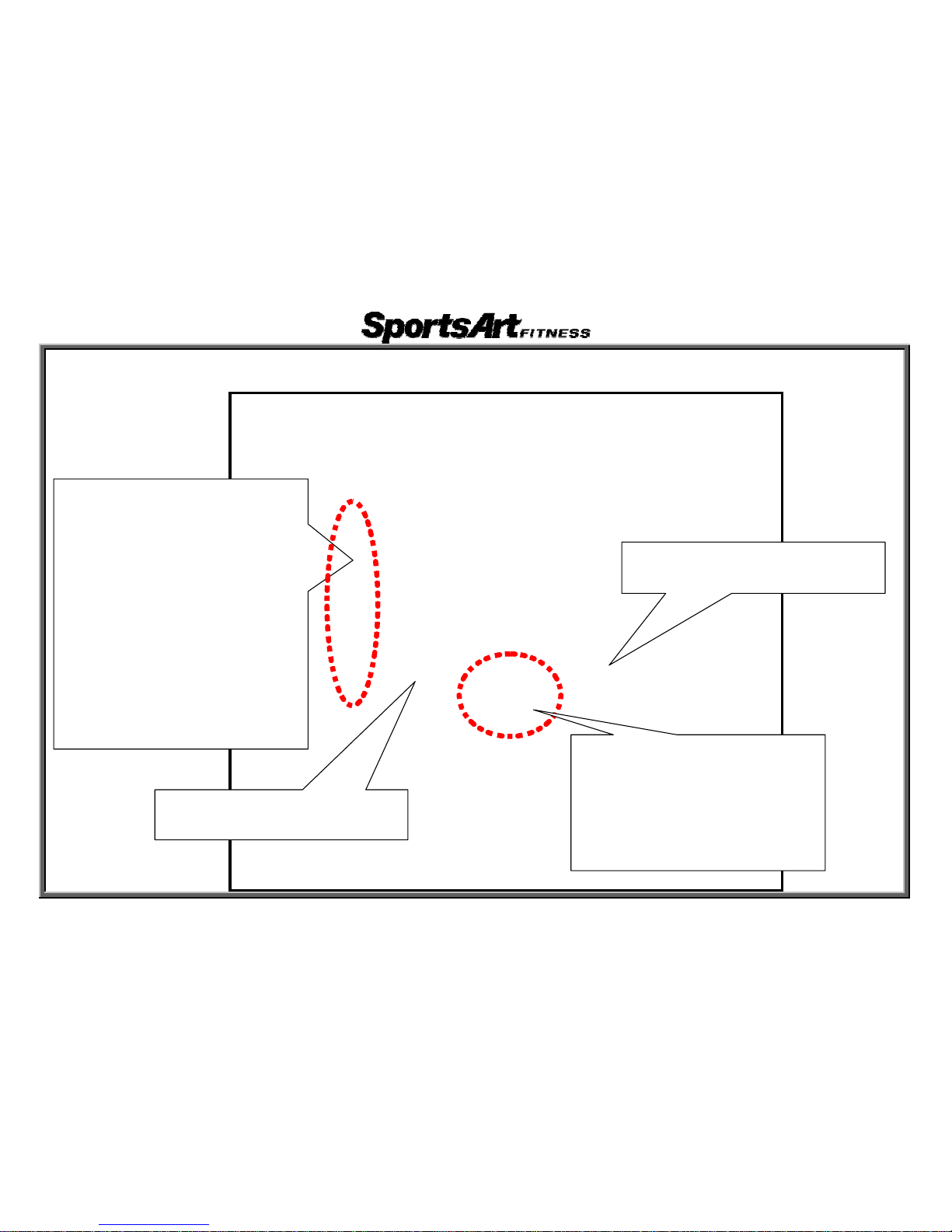
XT20 Display Key Functions
2-3-1
<MANUAL>
ÎKeys directly determine settings
<RANDOM>
ÎAutomatic random resistance
changes
<CARDIO/WT LOSS>
ÎAutomatic control according to heart
rate setting
<CONDITIONING>
ÎAutomatic physical conditioning
program (1)
<ADVANCED CONDITIONING>
ÎAutomatic physical conditioning
program (2)
LEG WORK LEVEL<▲>/<▼>
ÎSet LEG resistance level
<START>Î start by inputting
personal information
<QUICK START>Î start without
inputting personal information
<ENTER>Î confirm your selection
<STOP/RESET>Îstop/reset
ARM WORK LEVEL<▲>/<▼>
ÎSet ARM resistance level

3-1-1
1. Battery Start Up
Function: 1. Use battery power to activate the unit.
Operation: 1. Press <START>. The display shows “XT20” and starts operating as shown below.

3-1-2
2. Alternator Start Up
Function: 1. Use power from the alternator to activate the unit.
Operation: 1. Move the pedals or handles. The display shows “XT20” and starts operating as shown
below.
Left Picture Right Picture

3-1-3
3. Quick Start Mode
Function: 1. Start exercising without inputting personal settings.
Operation: 1. To start exercising, press <QUICK START> after the display shows “XT20”.
The display will appear as shown below on the left.
2. Move the pedals or handles. Time accumulates from 0:00.
3. Press <STOP/RESET>. Exercise mode stops. The startup screen appears as shown on the right.
Left Picture Right Picture

3-1-4
4. Operating from Quick Start Mode
Function: 1. Exercise from QUICK START in manual mode
Operation: 1. The default settings in this exercise mode follow: age is 35; weight is 75Kg/165Lb;
arm resistance is 3; leg resistance is 5.
2. The course is represented by an oval track. Green dots represent area yet to cover;
orange represents current location; red represents area already covered. See picture below left.
3. While you exercise, CALORIES/CAL HR, DISTANCE, METS/WATTS values show.
Distance values accumulate. RPM values appear for both legs and arms. See picture below right.
4. Directly press LEG WORK LEVEL▼/▲ or ARM WORK LEVEL▼/▲ keys to control
resistance settings.
Left Picture Right Picture

3-1-5
5. LEG/ARM Work Level Setting
Function: 1. Set LEG/ARM resistance level.
Operation: 1. Press the LEG/ARM Work Level ▼/▲ key on the display or press the ┼/— key on the handle
to change LEG and ARM resistance settings. Left: display keys. Right: handle keys.
2. Left handle ┼/— keys set leg resistance. Right handle ┼/— keys set arm resistance.
Resistance setting range: 1~20.
Left Picture Right Picture

3-1-6
6. Start Mode
Function: 1. Exercise using user personal information for more accurate physical feedback readings.
Operation: 1. Press <START> after the display shows “XT20” to input user information. The display appears
as shown on the left.
2. To enter age and weight, press ▲\▼ keys or numbers on the bottom of the display.
Press <ENTER> to confirm your choice as shown below on the right.
3. After pressing <ENTER>, the display, automatically calculates calorie burn, etc., according
to your information.
Left Picture Right Picture

3-1-7
7. Operate Programs
Function: 1. Operate automatic programs.
Operation: 1. After entering age and weight information, all program LEDs light as shown on the left.
2. Press any key (MANUAL、RANDOM、CARDIO/WT LOSS、CONDITIONING、ADVANCED
CONDITIONING) as shown on the right to activate the related program.
3. Programs explanations follow: (1) MANUAL-directly set resistance; (2) RANDOM-resistance
changes at random; (3) CARDIO-aerobic conditioning; WT LOSS-weight loss
mode; (4) CONDITIONING-physical conditioning; (5) ADVANCED CONDITIONING –
advanced physical conditioning.
Left Picture Right Picture

3-1-8
8. Operating Programs (Cont.)
Function: 1. Other program operation.
Operation: 1. After entering a program (MANUAL、RANDOM、CARDIO/WT LOSS), press ▲\▼ keys
on the display or handles to enter the time, then press <ENTER> to confirm your choice.
2. In CONDITIONING and ADVANCED CONDITIONING modes, press these keys again to toggle between
four options, P1~P4. Exercise time is pre-set. Press <ENTER> to confirm your choice of programs. The
display appears as shown on the right.
Left Picture Right Picture

3-1-9
9. Stopping Programs
Function: 1. Program mode values and prompts.
Operation: 1. In program modes, press <STOP> to halt the program. The display appears as shown
on the left.
2. After stopping, the display shows total distance, calorie expenditure, and time. See right.
3. To resume your workout, hold the <STOP/RESET> key two seconds. The display will reset.
Left Picture Right Picture
 Loading...