

SportsArt Fitness T650, T650M Repair Manual

T650/T650M Treadmill Repair Manual
SPORTS ART INDUSTRIAL CO., LTD.

【Table of Contents】
1. Main Component Placement
1-01. T650/T650M Treadmill Complete
1-02. Display Area
1-03. Hood Area
1-04. Display Area Keys
1-05. Display Inside
1-06. Drive Board
1-07. AC Servo Motor
1-08. Other (1): LCD, Keys, Fan Board, Telemetry Board
1-09. Other (2): HTR Board, Key Board,
2. Introduction
2-01. Specifications
2-02. Display Features
2-03. TFT Screen
2-04. Display Indicators
2-05. Display Area Keys
2-06. Display Circuit Boards
4-04-01. Fan Operation
3. Operation
3-01-01.Operation
4. Cable Connections
4-01-01. Display Board Cable Connections
4-01-02. Display Area Board Cable Connections
4-02-01. Drive Board Cable Connections
4-02-02. Drive Board Cable Connection Block Diagram
4-03-01. AC Incline Operation - Time
4-03-02. AC Incline Operation - Voltage
AV Board, EMI Filter
5. Error Messages
5-01. Error Code Overview
5-02. E-1-1 – Encoder Error
5-03. E-1-2 – Motor Overheat Error
5-04. E-1-3 – Motor Spee d Error
5-05. E-2-1 – IGBT Excessive Current Error
5-06. E-2-2 – IGBT Excessive Heat Error
5-07. E-3-1 – Incline Calibration Error
5-08. E-4-2 , E-4-3 Low/High Voltage Errors
5-09. E-8-1 – No Display-Drive Board Communication at Start
5-10. E-8-2 – No Display-Drive Board Communication During
Operation
6. Troubleshooting
6-01. Motor Does Not Operate
6-02. Display Soft Key Malfunction
6-03. Unit Will Not Start Up
6-04. Incline Motor Does Not Operate
6-05. The Fuse Blew
6-06. Telemetry Heart Rate
6-07. HTR Heart Rate Malfunction
6-08. Safety Key Does Not Operate
6-09. Fan Malfunction
7. Testing
7-01. EMI Filter
7-02. Motor
7-03. Inductor
7-04. Incline Motor V oltage
7-05. Incline Calibration Switch
7-06. Safety Key Switch
7-07. Telemetry Reception
7-08. Heart Touch Rate (HTR) Board
7-09. HTR Handlebar
7-10. Motor Thermal Sensor
7-11. Fan Board Voltage
7-12. Power Supply at the Drive Board
3. Display Board V oltage
7-1

【Table of Contents】
8. Mechanical Adjustments and Part Replacement
8-1. T650(M) Treadmill W alk Belt T ightness Adj ustment
8-2. T650(M) Treadmill Walk Belt Alignment
8-3.AC Motor Incline Calibration Pro
8-4.AC Motor Incline Calibration Pro
cedure - Software
cedure - Hardware
1.Product Picture
1-01-01

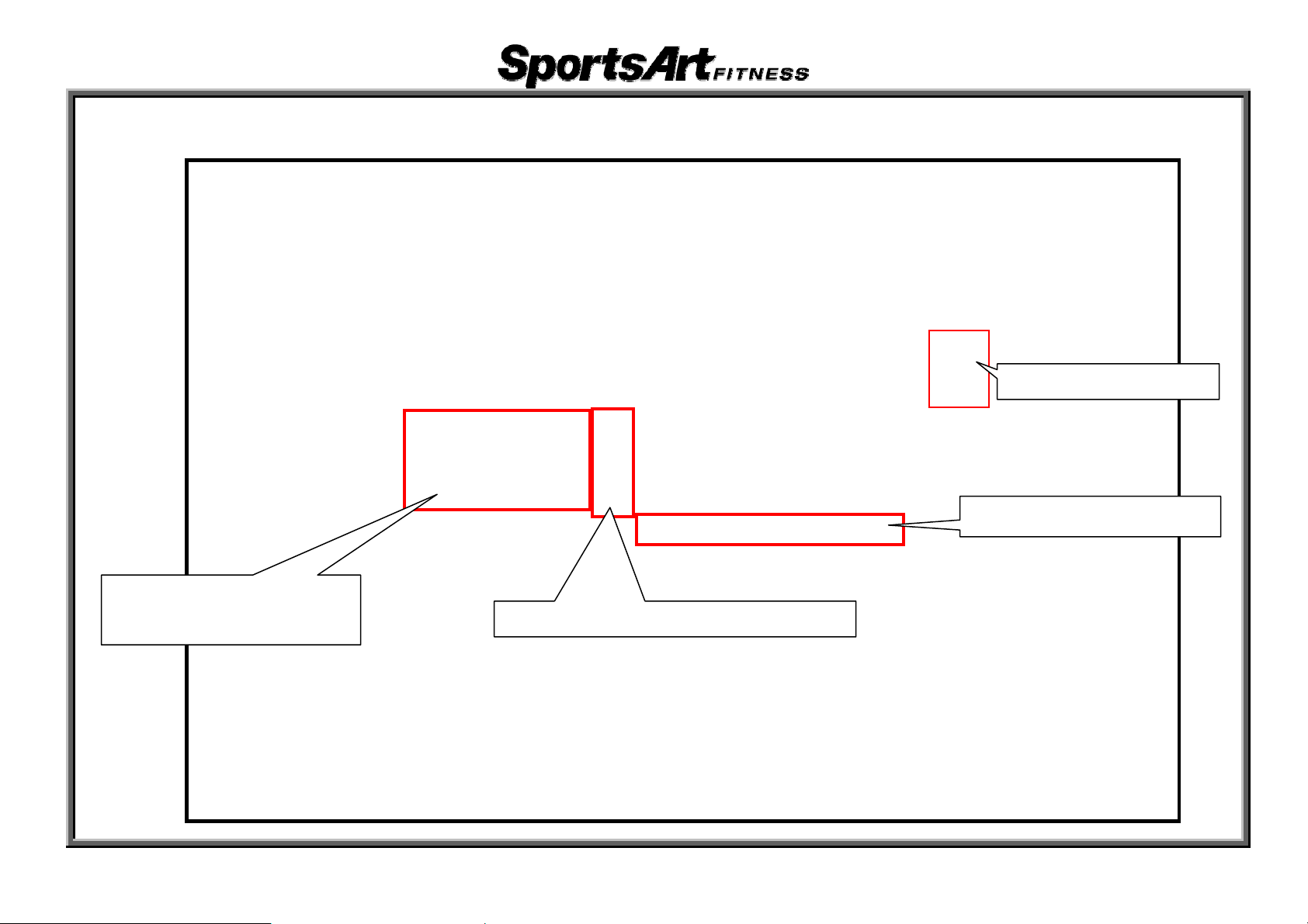
2. T650 /T650M Components-Display Area
Heart Rate
Singal
PROGRAM Keys
QuickStart key
Stop key
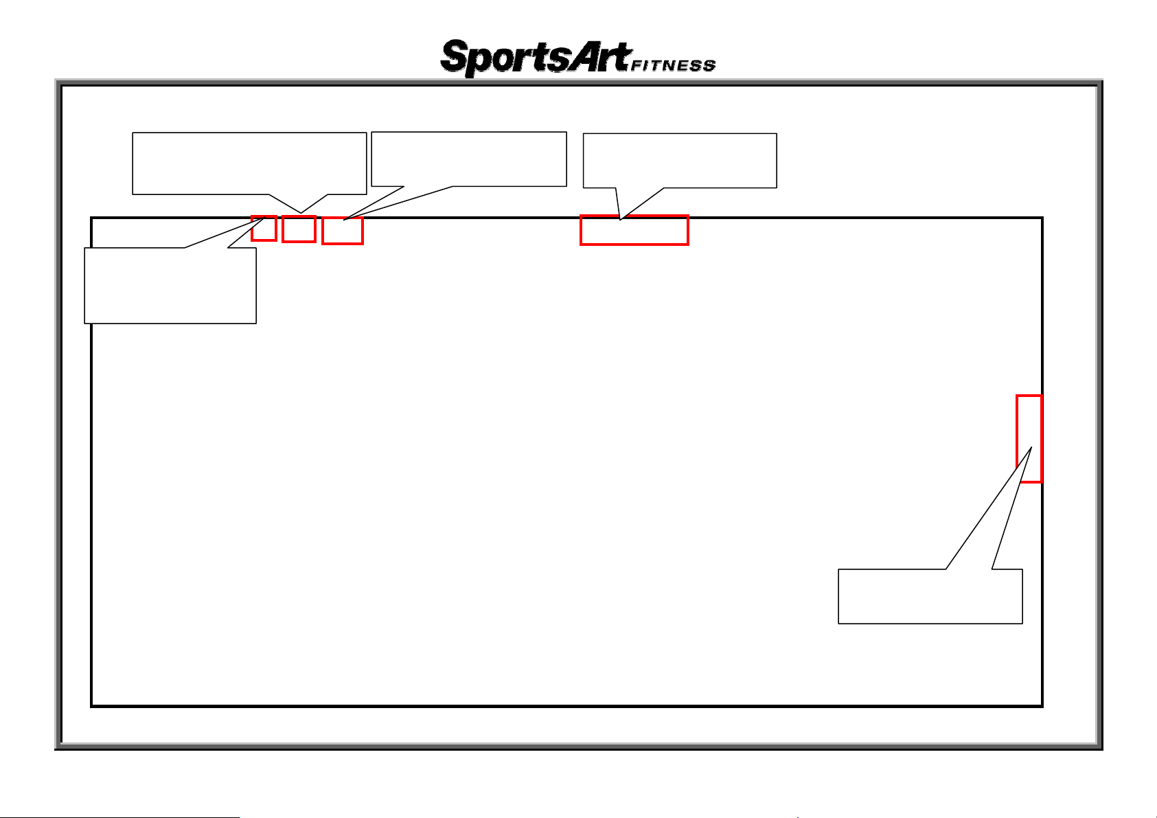
1-01-02
Incline key
Feedback Screen
Setting number Keys
Speed key
3. T650/T650M Components-Motor Area
EMI Filter
Incline -3% Switch
AC SERVO Motor
Incline Set
Incline 0% Switch
1-01-03
Drive Board

4. T650/T650M Display
Q
Change Display key
Number and CLEAR keys
ÎProgram mode keys
UICK START,START,ENTER keys
1-01-04
5. T650/T650M Components – Display Area-Display Board
1-01-05
6. T650/T650M Components – Drive Board
1-01-06
7.T650/T650M Components – AC Servo Motor
Encoder
1-01-07
8. T650/T650M Components - Other(1)
Part
EMI Filter (220V) Part EMI Filter (110V)
Part BRIDGE Board Part Telemetry Receiver Board
1-01-08
9. T650/T650M Components - Other(2)
Part
HTR Board
Part Soft key
Part SAFETYKEYBoard Part Encoder
1-01-09
T650/T650M Specifications
Specification Deta Notes ils
Pow Exteer Supply rior Power Supply 110V (USA);
220V (Europe)
HRC
Main
Hea
Window Display
Sec
Display
Spe
ed Range
Incli
ne Range
rt Rate Detection
KPH Prog
/MPH Setting ram
heart rate window: 65%, 80%, Heart
a
R
te, Calories, S
Cal/hr, Mets, Pace, Incline
Dot
Matrix 15 X 8 Window
T65
0(M)
T65
0M
Rev
erse mode
T65
0 :0 % TO 15 %
T65
0M:-3% TO 15%
HTR
Heart Touch Rate (contact pads) e
Wir
less Telemetry Heart Rate (HR
T
peed, Time, Distance,
0.2 -
0.1
ransmitter)
20.0KPH
– 12.0MPH
0.
2-5KPH
0.1-
3MPH
ondary Window
AC
Motor
Prog
ram/Control
Man
Ope
ration
ual,Hill,Random,Interval,T
,WT
Loss,Zone Trainer,FAT BURN,Glute ,
2-1-1
rack,FITTEST
T650/T650M Display
2-01-02

r
T650/T650M Introductions- Display Board (Heart Rate Indicator)
Heart Rate Indicator
Display Lock/Unlock
Key and Indicator
Î Lit indicat
active row and
scan/lock mode.
Number Key and Indicator
es the
Workout Programs
Î Lit indicat
MANUAL,HILL,RANDOM,INTV,TRACK,GLUTE
,FAT BURN,ZONE TRAINER,WtLOSS/CARDIO 模
式
es active program:
ENTER Key and Indicato
2-01-03
T650/T650M Introduction- Display Board (Keys)
Q
Change Display key
Number and CLEAR keys
ÎProgram mode keys
UICK START,START,ENTER keys
2-01-04

T650/T650M Operation
1. Start Up
Function: Press the Quick Start key to start operating the unit.
Operation: (1) The display shows “SPORTSART – T650”.
QUICKSTART” scrolls across the di
the PROGRAM key to operate an exercise program.
(2) The PROGRAM LED flashes After pressing a program key
lights up. The setting window shows two seconds. If you press the <RANDOM> key,
the RANDOM LED lights. “RANDOM” appears.
(3) User age and weight setting When “AGE – 35”
INCLINE▲/▼. Then press the <ENTER> key to confirm your setti
When “W
Then press the <ENTER> key to confirm your setting.
(4) After entering such information, you can start operating the treadmill.
EIGHT -- 75 KG” appears, press the numerical keys or INCLINE▲/▼.
splay.Press the QUICK START key to start operating or press
2.SPEED Key
Function: Set speed function
Operation: (1) Press the SPEED <▲> key. Values i
(2) Press the SPEED <▼> key. Values in the speed wi
(3) SPEED range: 0.2~20 KPH (0.1~12 MPH).
n the speed window increase. Speed increases.
After two seconds, “SELECT PROGRAM OR
, the associated program indicator
appears, press the numerical keys or
ng.
ndow decrease. Speed decreases.
3-1-1

3.INCLINE Key Function
Function: Set treadmill incline position.
Operation: (1) Press the INCLINE<▲> key. Values in the incline window increase.
Incline operates up.
(2) Press the INCLINE<▼> key. Values in the incline window decrease.
Incline operates down.
(3) INCLINE range: 0~15%
; increments of 0﹒5%.
4.STOP Key Function
Function: Leave an exercise program.
Operation: (1) In QUICKSTART mode, press the<STOP>
key to leave the exercise program.
(2) If in the START mode, having entered user information, press the<STO
stop exercising. Feedback pauses as is.
(3) In any mode, hold the<STOP>
and return to start up screen.
key three seconds to leave the present mode
5.CHANGE Key Function
Function: Change the display feedback row.
Operation: (1) Press the <Change Di
feedback row to another feedback row. Correspondi
CALORIES、SPEED、TIME、DISTANCE. Bottom row: C
scan
(2) In SCAN mode, the SCAN LED lights. Every four seconds, the display toggles
from one feedback row to the other row. If you press the SCAN key again, the
LED extinguishes. The display continues to show the activated feedback row.
splay> key while exercising to toggle from one
ng LEDs light. Top row:
AL/HR、METS、PACE、INCLINE.
P> key to
3-1-2

6.CLEAR Key
Function: Clear entered values to 0.
Operation: Press to clear entered values to 0.
7.PROGRAM Key
Function: Select exercise programs.
Operation: (1) Press any PROGRAM key
. Its corresponding LED lights.
(2) Programs include MANUAL、HILL、RANDOM、INTV、TRACK、FA
T TEST、Wt LOSS、ZONE
TRAINER、FA
T BURN、GLUTE
8.T650M Reverse Mode
Function: Enter reverse mode.
Operation: (1) Activate the treadmill through ST
(2) Once the treadmill is operating, press the MANUAL-REVERSE key
REVERSE or MANUAL appears. Press up or down keys to toggl
between the two modes. Press the ENTER key to confirm your choice.
(3) Reverse mode cannot be accessed through QUICK ST
(4) Forward speed range: MPH: 0.1~12 MPH; KPH: 0.2~20 KPH.
Reverse speed range: MPH: 0.1~--3 MPH; KPH: 0.2~-0.5 KPH.
ART mode, entering user age and weight.
.
e
ART mode.
3-1-3
9. Basic Settings
Function: (1) Set KPH/MPH, total distance, and total time.
Operation: (1) Hold the <Change Display> key for three seconds to enter the basic setting m
Message
Press the INCLINE<▲/▼>key to change your setting.
(2) Press the <ENTER> key to see the total distance:
“DIST
(3) Press the <ENTER> key to see the total time:
E-XXXXX HOUR”.
T650_1X”.
“DRV T650_X”. Press the <ENTER> key to return to the startup screen. Or press t
<STOP> key to exit the basic setting mode.
“TIM
(4) Press the <ENTER> key to see the display m
“CTL
(4) Press the <ENTER> key to see the drive board main program
window shows the current setting as either “UNIT - MPH” or “UNIT - KPH”.
-XXXXX KM”.
ain program IC version, for example,
IC version, for example,
ode.
he
3-1-4
T650/T650M Cable Connections-Display Board Cable Connections
(
y)
CON3:
To BRIDGE board( HTR )
CON2:
TO BRIDGE
Board
safety ke
CON4:
To HRC board
CON1:
To drive board
CON5:
TO BRIDGE Board
4-01-01
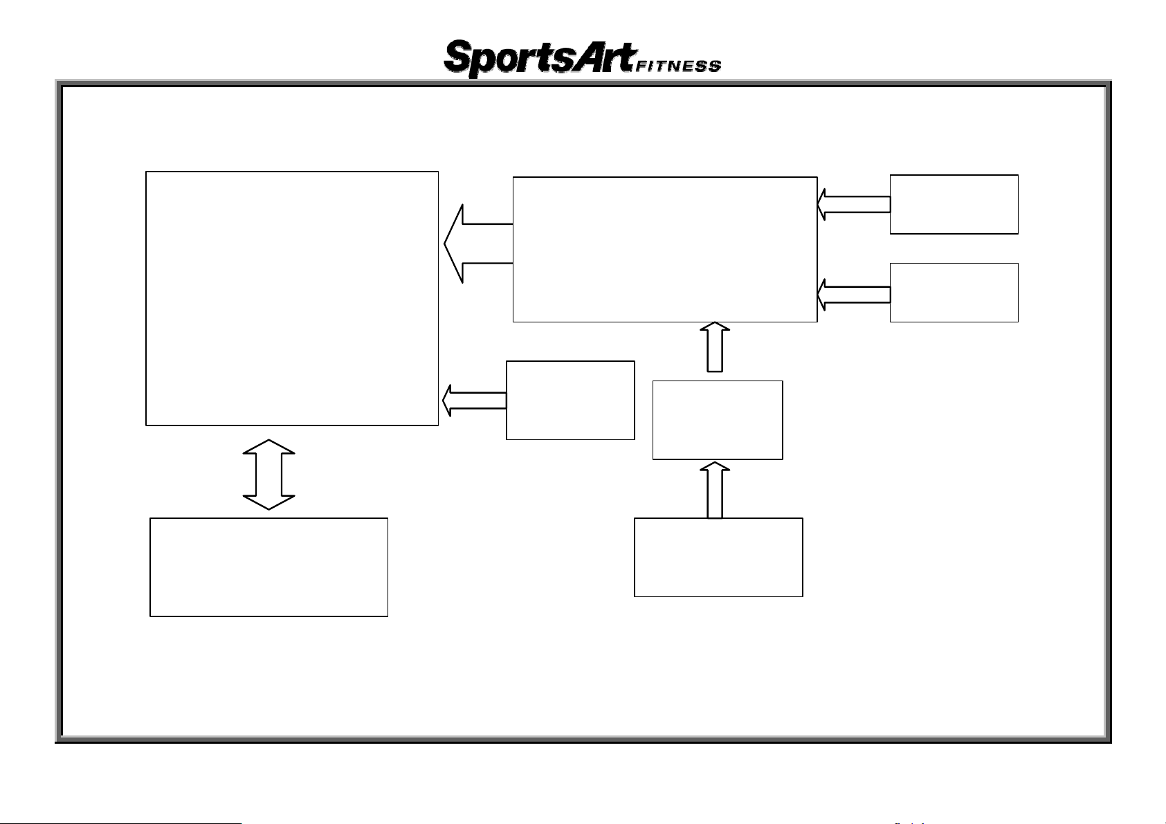
T650/T650M Cable Connections - Display Board Cable Connection Block Diagram
Display Board
CON1
Drive Board
CON2
CON3
CON5
CON4
CON5
BRIDGE Board
Telemetry
Board
CON4
CON1
CON2
HTR
Board
HTR Handlebar
Soft key
SAFETYKEY
4-01-02
T650/T650M Cable Connections - Drive Board Cable Connections
CON1
o thermal sensor
ÎT
CON2
ÎT
o drive motor
CON3
o power supply
ÎT
CON4
o inductor
ÎT
CON5
o incline motor
ÎT
CON6
o motor encoder
ÎT
CON7
o display board
ÎT
CON8
o incline calibration sensor
ÎT
4-02-01
CON9
o display power
ÎT
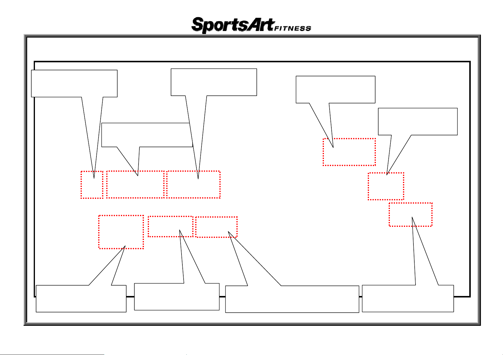
T650/T650M Cable Connections-Drive Board Cable Connection Block Diagram
Power
Cord
Display Board
Fuse
On/Off
Switch
EMI
Filter
Inductor
(220V only)
Drive Board
AC Inclin e
Motor
Encoder
Thermal
Sensor
Calibration
Switch
4-02-02
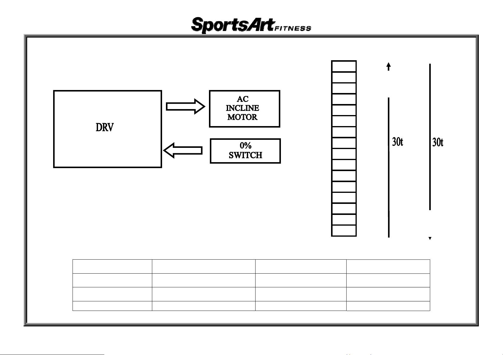
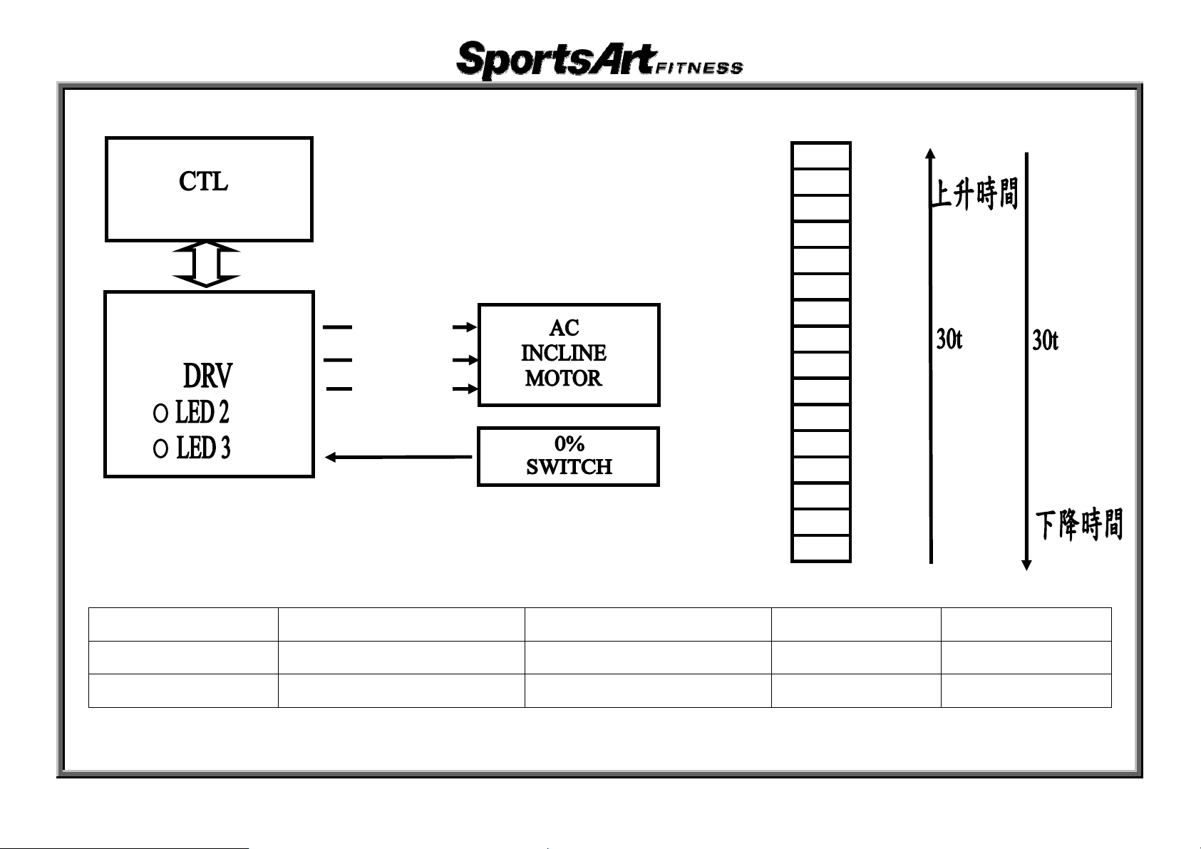
T650/T650M Cable Connections-AC Incline Operation - Time
1. Turn on the unit. Incline recalibrates to 0﹪.
15%
14%
13%
12%
11%
10%
9%
8%
7%
6%
5%
4%
3%
2%
1%
0%
Up Travel
Time
Down Travel
Time
Model Every 0.5% Incline Time (0%-15%) Decline Time (15%-0%)
T680
T670
T650
t=1s
t=1s
t=0.9s
30s 30s
30s 30s
27s 27s
4-03-01
T650/T650M Cable Connections - AC Incline Operation - Voltage
Black – Up
Red – Down
White - N
15%
14%
13%
12%
11%
10%
9%
8%
7%
6%
5%
4%
3%
2%
1%
0%
DISPLAY DRV LED Output Voltage
UP LED 3→ON(UP) Black - White 110v/(220v)
DOWN LED 2→ON(DOWN) Red - White 110v/(220v)
4-03-02
Incline Operation
Down
Up
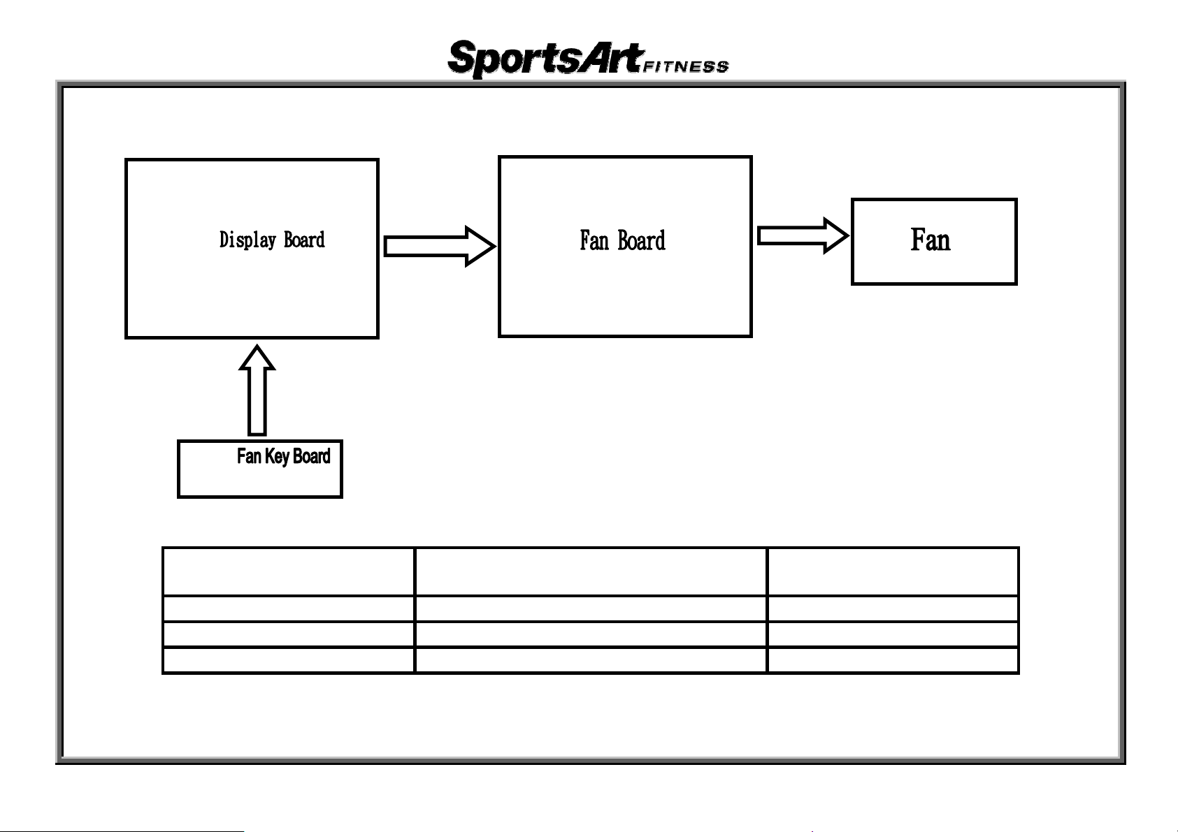
T650/T650M Cable Connections - Fan Operation
DISPLAY
Fan Board
Voltage Output
FAN-HIGH DC 12V High
FAN-MID DC 9V Medium
FAN-LOW DC 6V Low
4-04-01
FAN
(Output)
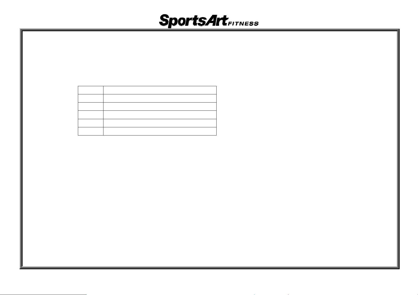
T650/T650M Error Messages-Error Code Overview
1. Display Format: ERROR_X_Y_
X and Y above are placeholders. In their place are digits.
The X placeholder represent
Digit Represents
1 Servo motor abnormality
2 IGBT abnormality
3 Incline motor abnormality
4 Power supply abnormality
8 Signal abnormality
2. Complete codes follow:
ERROR_1_1_:Servo motor encoder malfunction. Re-start machine.
ERROR_1_2_:Servo motor has overheated. Unit operates at half speed.
ERROR_1_3_:Servo motor sped up without command. Re-start machine.
ERROR_2_1_:IGBT excessive current. Re-start machine.
ERROR_2_2_:IGBT excessive heat. Unit operates at half speed.
ERROR_3_1_:Incline motor recalibration error.
ERROR_4_1_:Power switch is off.
ERROR_4_2_:Power supply voltage is too low. Re-start unit after power supply is stabilized.
ERROR_4_3_:Power supply voltage is too high. Re-start unit after power supply is stabilized.
ERROR_8_1_:Signal error upon start up.
ERROR_8_2_:Signal error after start up.
s the following category of abnormalities.
5-01-01
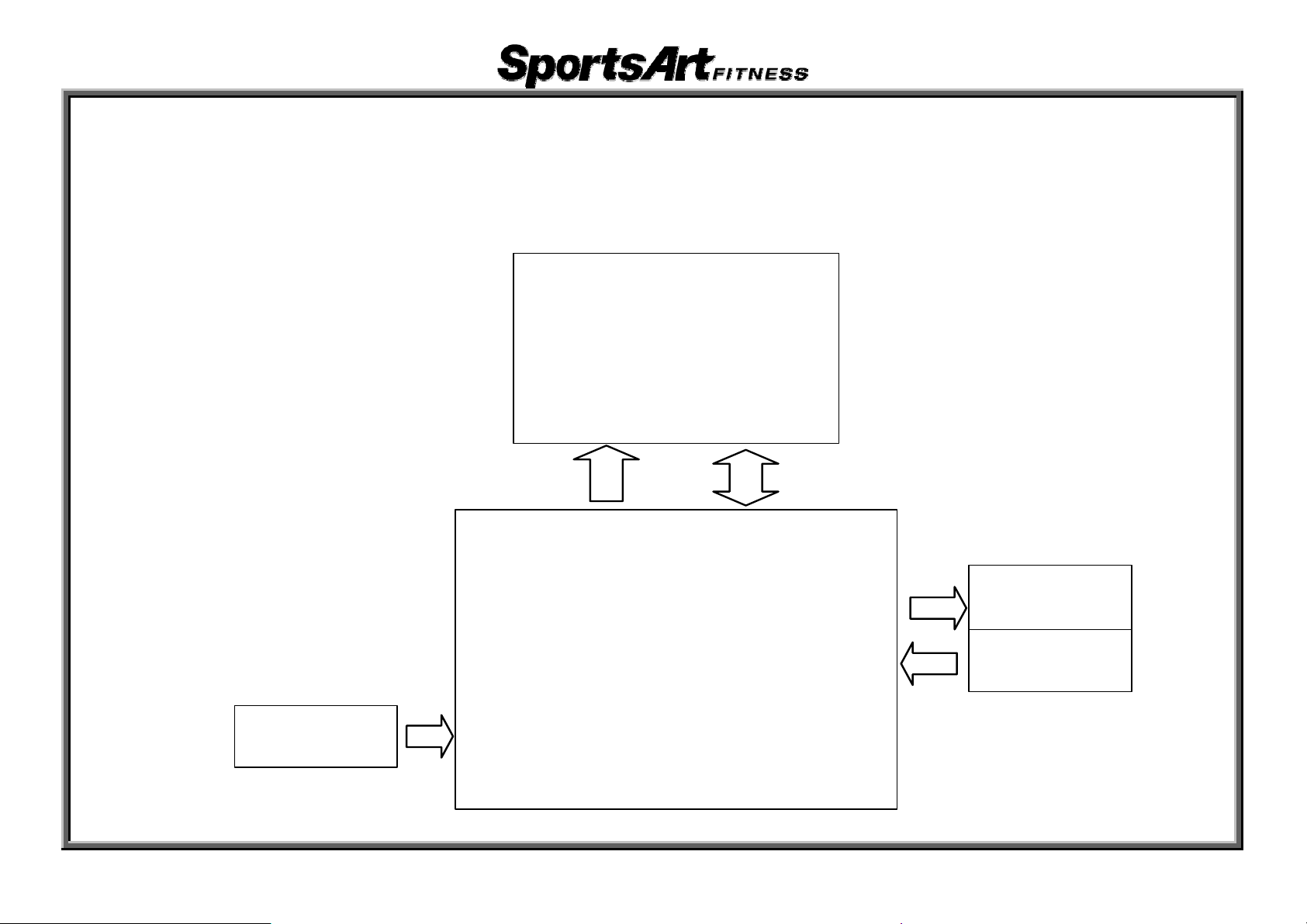
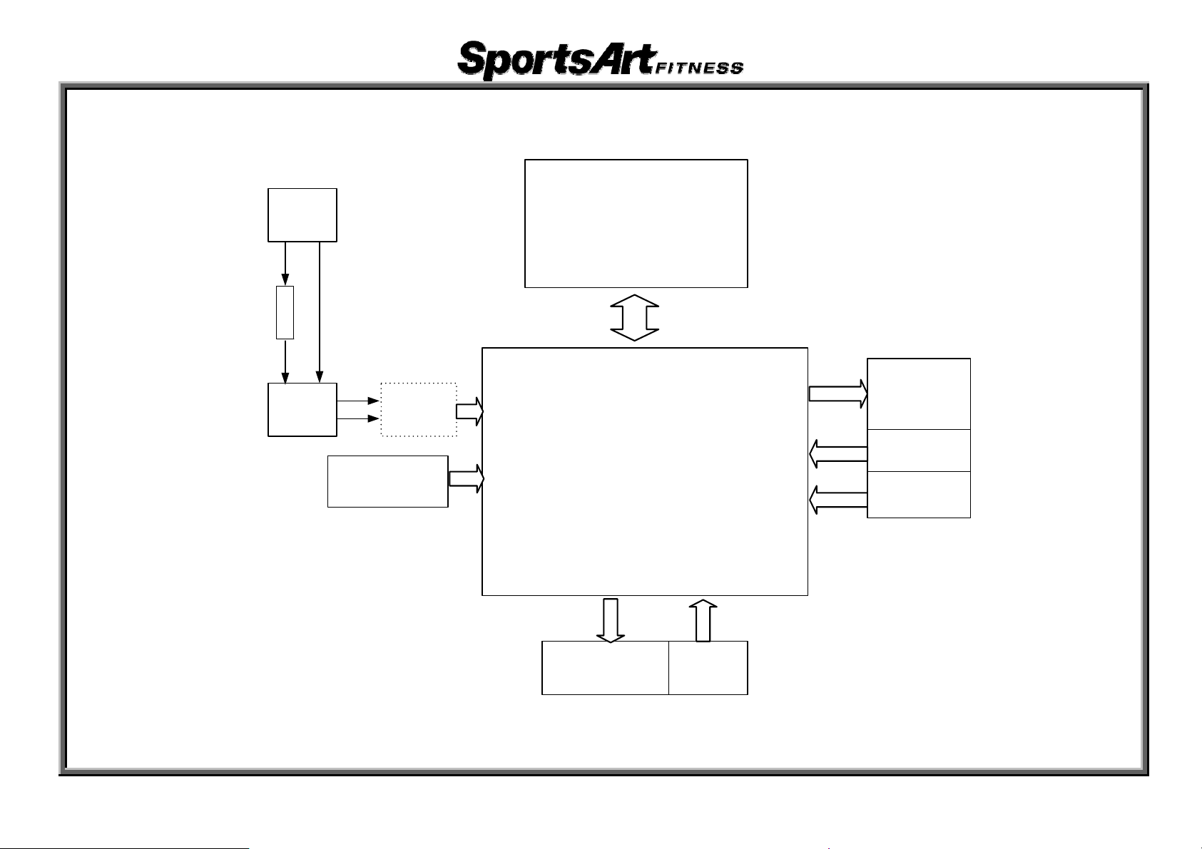
T650/T650M Error Message - E-1-1 - Motor Encoder Error
1. Circumstance of Malfunction: Display shows E-1-1; unit does not operate.
2. Block diagram
Display Board
Indu c to r
(220V only)
Drive B oard
5-02-01
Servo Motor
Encoder
3. Operation
Order Part Explanation
1. Tur nit power. Drive board detect
1 Drive Board
2 Dat able dea C The enco r signal is transmitted through the data cable.
3 Displ Boa
4 deEncoder Encoder tects motor speed and direction.
ay rd
2. Af ter co
to the disp
1. After de cting the drive board signal, the display maintains
communica
2. If the driv
on the disp
n on u
nf
la
te
ir ing the signal is OK, the drive board transmits the signal
m
y
.
tion with the drive board.
e board does not detect the encoder signal
ay.
l
s encoder signal.
4. Analysis
The reason E1-1 would appear is that the dri
5. Troubleshooting
A. Turn unit off and on.
B. Inspect whether the encoder wire is connected to the dri
C. Replace the servo motor.
D. Replace the drive board.
ve board does not detect the encoder signal.
ve board.
, E1-1 appears
5-02-02
 Loading...