

SportsArt Fitness G872 Owner's Manual


SPORTSART G872
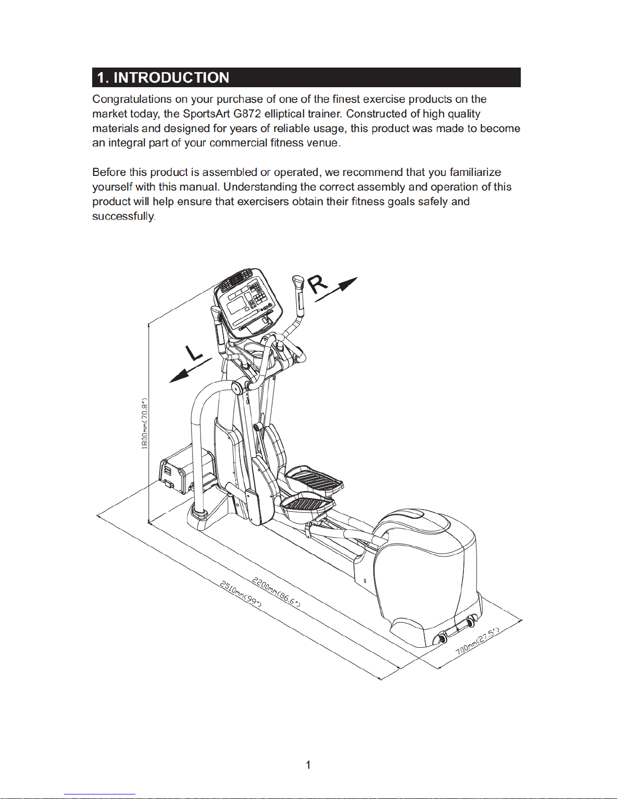
1. INTRODUCTION..................................................................................................
2. IMPORTANT SAFETY PRECAUTIONS...............................................................
3. LIST OF PARTS...................................................................................................
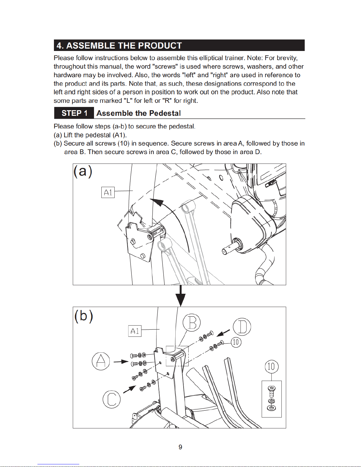
4. ASSEMBLING THE PRODUCT
STEP 1 Assemble the Pedestal.........................................................................
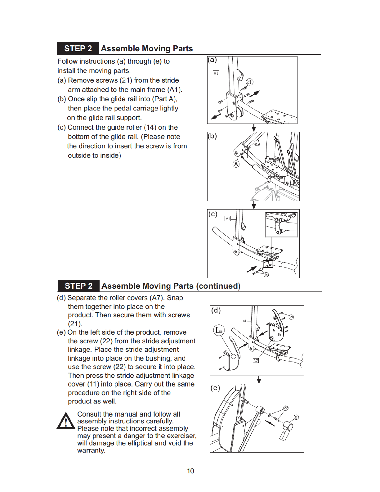
STEP 2 Assemble Moving Parts........................................................................
STEP 3 Install the Support Tubes......................................................................
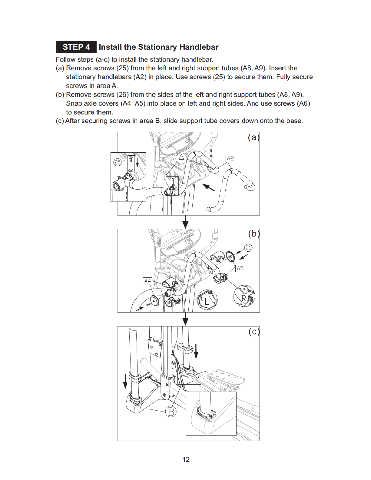
STEP 4 Install the Stationary Handlebar............................................................
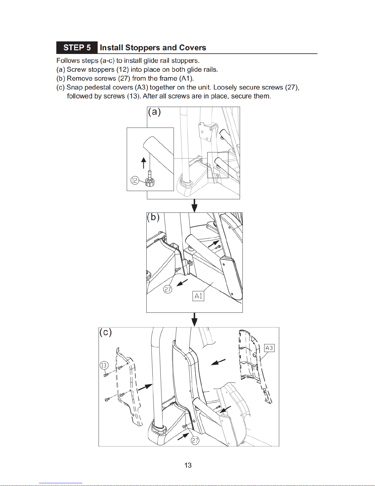
STEP 5 Install Stoppers and Covers..................................................................
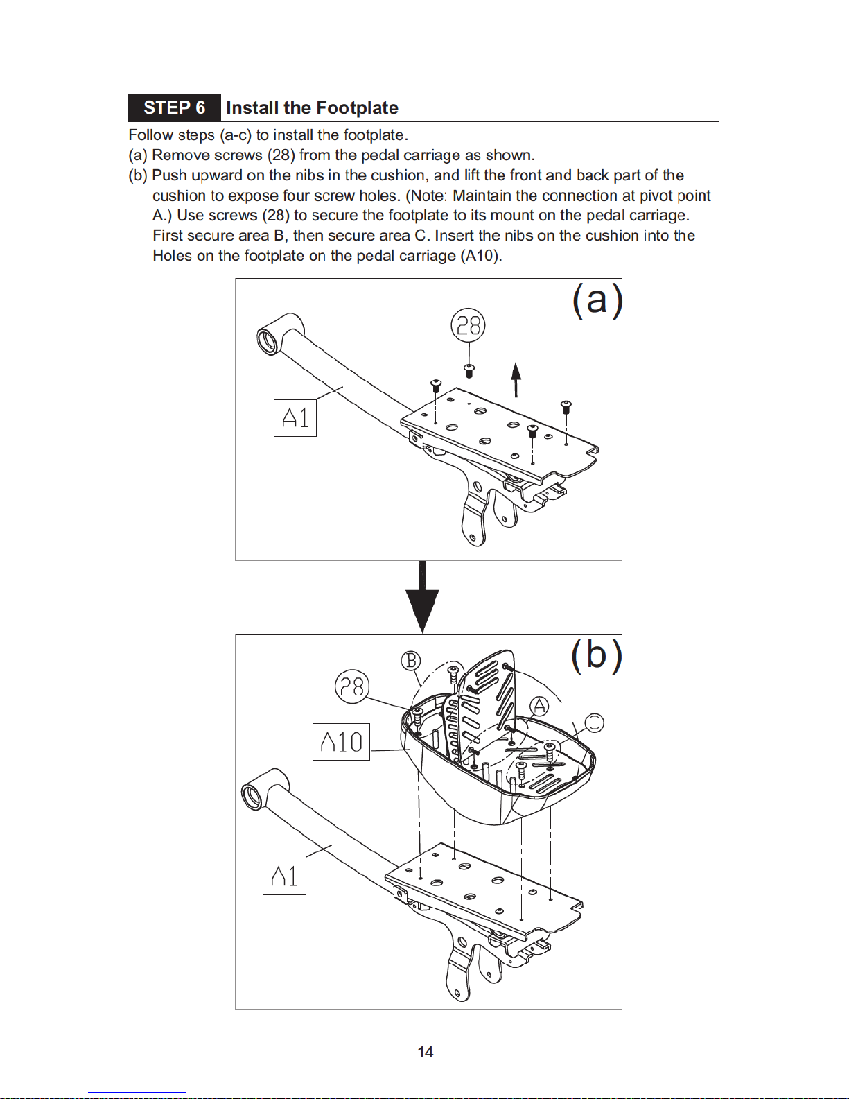
STEP 6 Install the Footplate...............................................................................
STEP 7 Move the Product into Place.................................................................
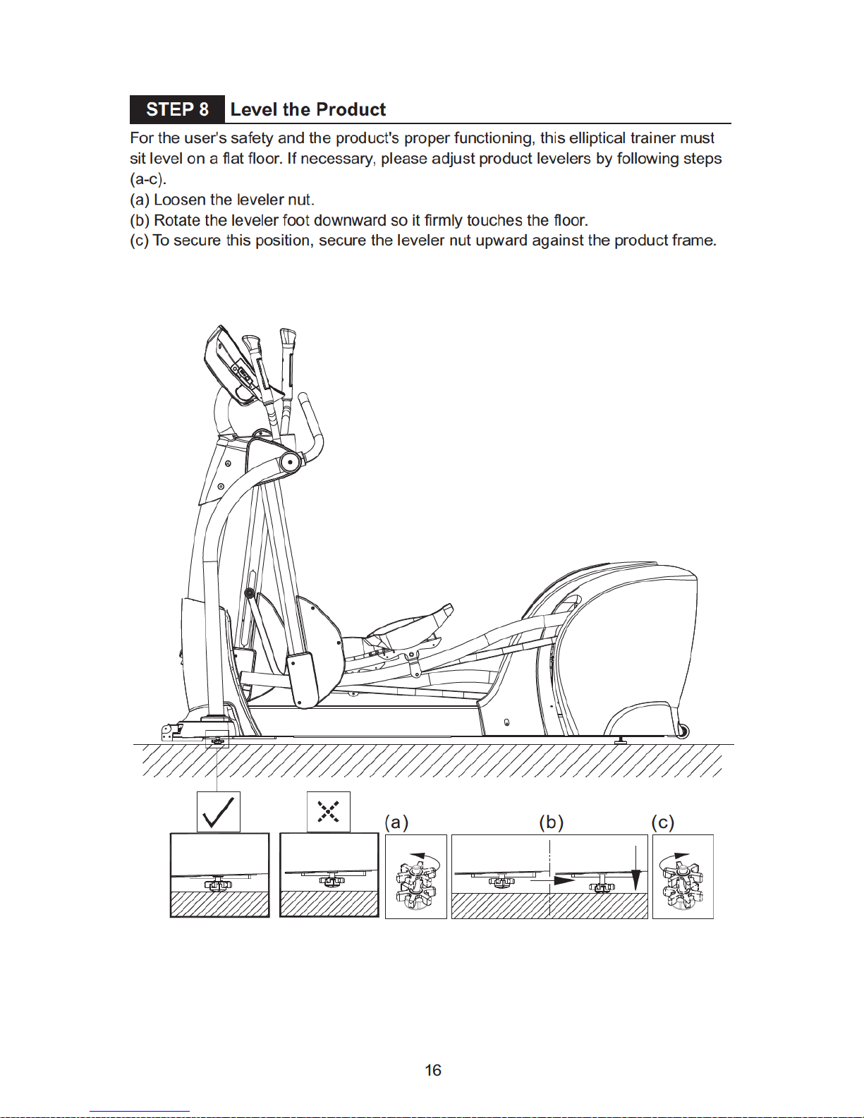
STEP 8 Level the Product..................................................................................
STEP 9 Install the Boost Converter Box.............................................................
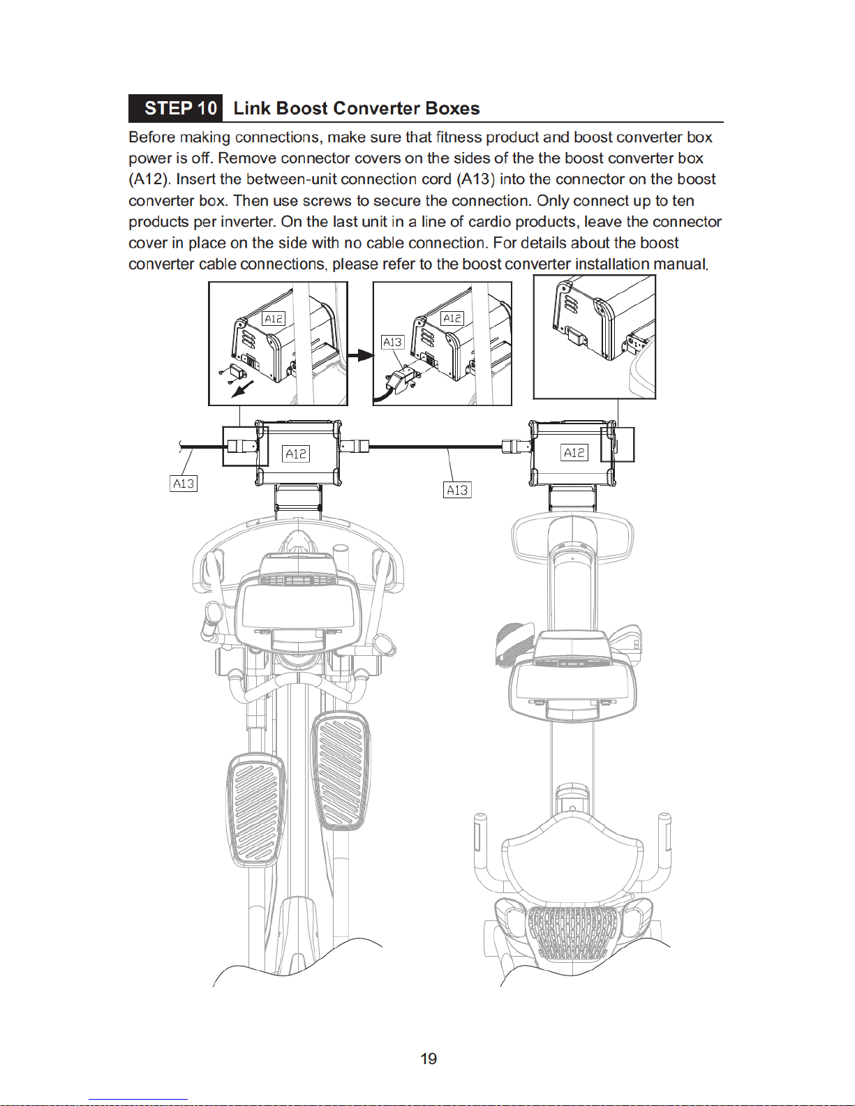
STEP 10 Link Boost Converter Boxes..................................................................
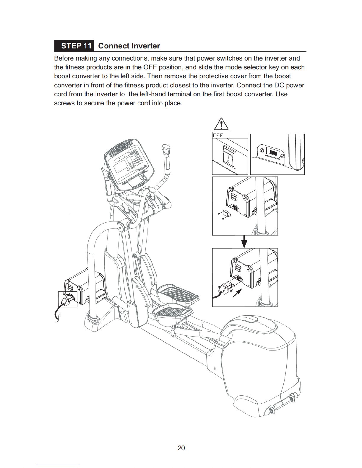
STEP 11 Connect Inverter.....................................................................................
STEP 12 Green System Connections...................................................................
STEP 13 System Inspection.................................................................................
STEP 14 Beware of Moving Parts........................................................................
STEP 15 Integrated TV Installation......................................................................
STEP 16 How to Set the Number of Fitness Products per Pod...........................
5. UNDERSTANDING THE G872 DISPLAY CONSOLE
DISPLAY Specifications........................................................................................
DISPLAY Overview................................................................................................
DISPLAY Windows................................................................................................
DISPLAY Keys......................................................................................................
DISPLAY Screens.................................................................................................
6. OPERATING WORKOUT SETTINGS
OPERATION Quick Start......................................................................................
OPERATION Workout Program Setup..................................................................
OPERATION Workout Program Operation...........................................................
OPERATION Switching Workouts.........................................................................
OPERATION Cool Down.......................................................................................
OPERATION Other Notes.....................................................................................
OPERATION User Preferences and Part Versions...............................................
7. ABOUT HEART RATE DETECTION AND PRESENTATION
HEART RATE Telemetry.......................................................................................
HEART RATE Contact..........................................................................................
8. GUIDELINES FOR EXERCISE
HOW HARD SHOULD I EXERCISE?...................................................................
HOW LONG SHOULD I EXERCISE?...................................................................
HOW OFTEN SHOULD I EXERCISE?.................................................................
ELLIPTICAL TRAINER
OPERATION Cumulative energy generating display (WH)...................................
1
2
7
9
10
11
12
13
14
15
16
17
19
20
22
23
24
25
26
28
28
29
30
32
TABLE OF CONTENTS
34
34
40
51
52
52
52
53
55
55
57
57
57

9. MAINTENANCE
MAINTENANCE Stride Worm Gear Lubrication....................................................
MAINTENANCE Messages...................................................................................
MAINTENANCE Cleaning......................................................................................
MAINTENANCE Disconnecting the Boost Converter Box.....................................
MAINTENANCE Schedule.....................................................................................
MAINTENANCE Task List (Elliptical Trainers).......................................................
MAINTENANCE One-Year Maintenance Log........................................................
10. BLOCK DIAGRAM...............................................................................................
11. GREEN SYSTEM SETUP INSPECTION CHECKLIST........................................
12. GREEN SYSTEM CABLE CONNECTION ILLUSTRATION................................
58
60
61
62
63
64
65
66
67
71


No. Name Qty
No.
QtyDescription
A1
A2
A3
A4
A5
A6
A7
2
1
1
1
1
Assembly Parts
A8
A9
A10
A11
A12
7
1
1
1
1
1
2
2
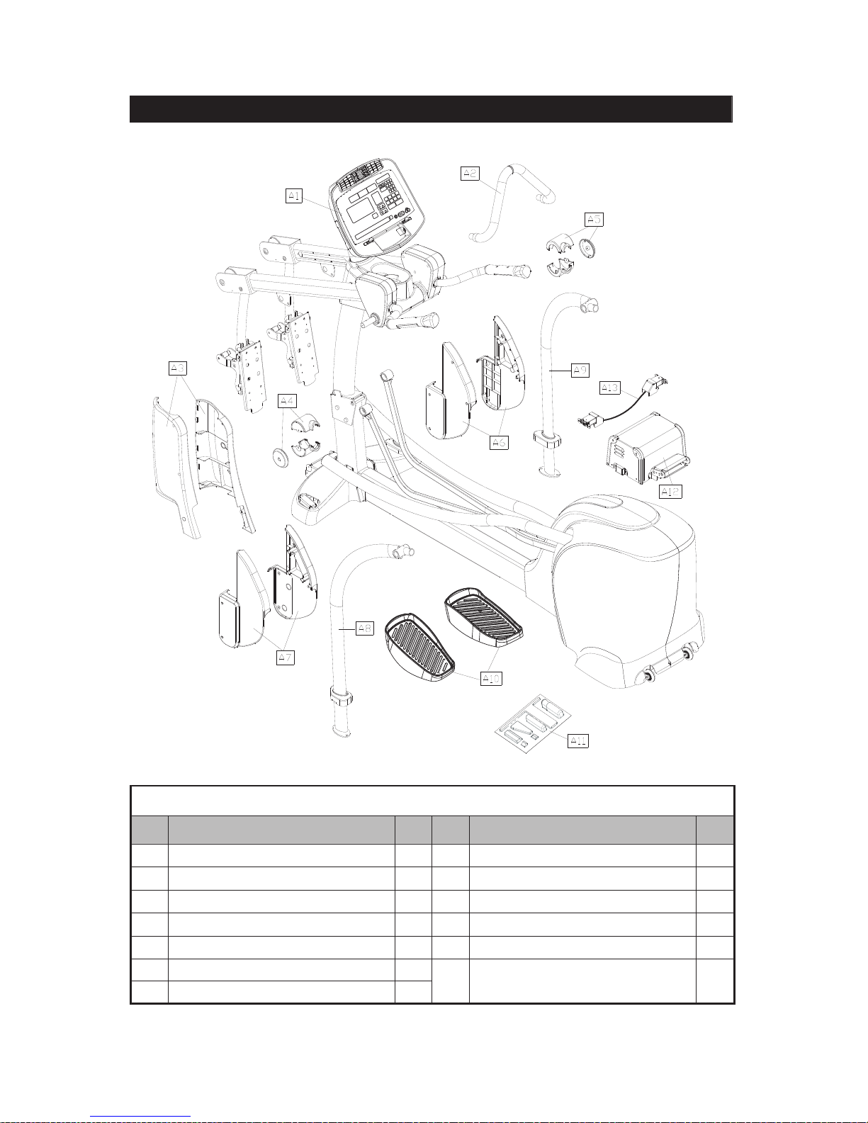
3. LIST OF PARTS
Main frame and body
Stationary handlebar
Pedestal covers, left and right
Joint cover, left
Joint cover, right
Right roller cover
Left roller cover
Support tube, left
Support tube, right
Footplate
Hardware kit
Boost converter box
A13
1
Boost converter box
connection wire
8
No. Name Qty
10
11
13
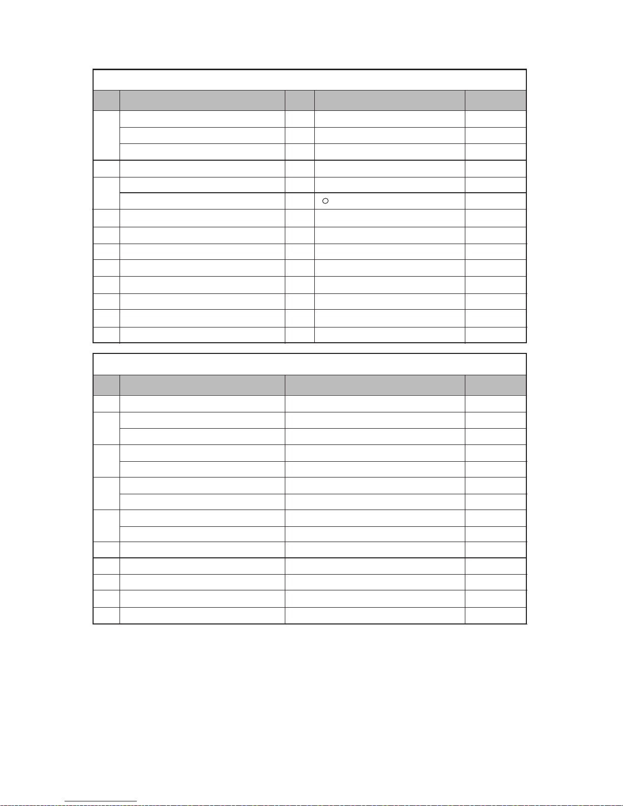
Parts in the Hardware Kit
6
6
6
2
2
2
4
1
1
1
1
1
1
1
Specification
Notes
No. Name
21
Parts on the Product
Specification
Notes
12
M10*P1.5*L25
M10
D16*d1.0*t1.0
M10*P1.5
30-30
M4*L12
M4
M5
M6
(8*17)
green
Flat and Phillips
ψ
22
23
24
25
26
27
28
29
30
M4*P0.7*L8
5/16"*L2-1/4"
D20*d8*t2.0
M6*L15
D20*d7*t2.0
M8*L15
M8
M6*L15
D20*d7*t2.0
M5*P0.8*L15
M5*0.8*L12
M5*L16
M6*P1.0*L10
Mushroom top inner hex screw
Spring washer
Washer
Stride adjustment linkage
Hex nut
Stopper
Phillips screw
L-shaped Allen wrench
L-shaped Allen wrench
T-shaped Allen wrench
Double open-end wrench
Double open-end wrench
Screwdriver handle
Screwdriver bit
Phillips screw
Inner hex screw
Flat washer
Inner hex screw
Handlebar washer
Mushroom top inner hex screw
Spring washer
Inner hex screw
Handlebar washer
Phillips screw
Mushroom top Phillips screw
Mushroom top inner hex screw
Beveled head Phillips screw
Connection wire
(14*15)

15
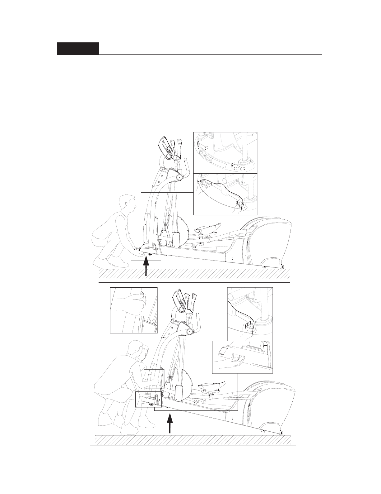
STEP 7 Move the Product into Place
(a) For one person: Grip the front base of the product and lift upward, then push the
product into location for use. Be careful to avoid pinching fingers when setting the
product down.
(b) For two people: Have one person grip the front base of the product while the
other person grips the support tubes (A8, A9). With both people lifting and
stabilizing the unit, roll it into place for use. Be careful to avoid pinching fingers
when setting the product down.
(b)
(a)
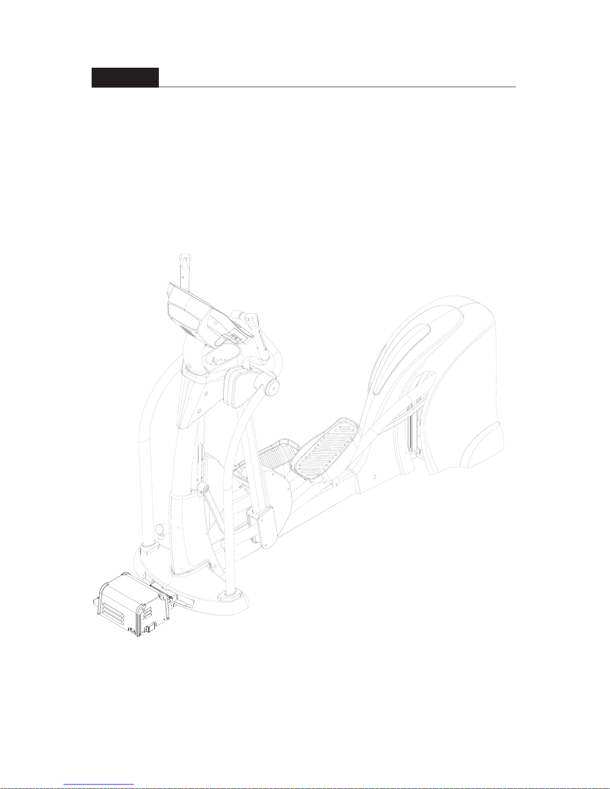
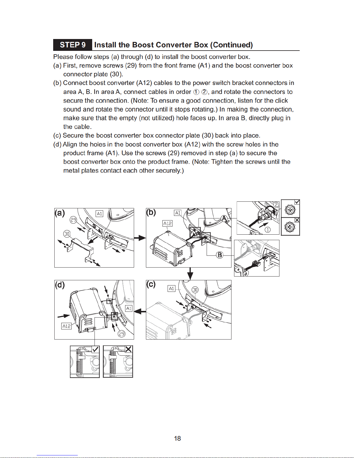
STEP 9 Install the Boost Converter Box
17
Note: A ground wire and the following instructions are required by European safety
standards. The ground wire is not required by North American safety standards.
To avoid electric shock and current leakage, this product has an exterior ground wire.
For your safety, connect this ground wire to the unit and to the building ground.
Installation instructions: Please use screws and washers to secure one end of the
ground wire to the product frame as shown and the other end to the building
electrical ground.
 Loading...