

SportsArt Fitness G862 Owner's Manual
Sports Art Industrial Co., Ltd. TUV-CERT ISO 9001/9002/14000 Certied Quality Products 2012.07.22
G862 Elliptical Trainer
Owner’s Manual

G862 OWNER’S MANUAL CONTENTS
1. INTRODUCTION .............................................................................. 2
2. SAFETY PRECAUTIONS ................................................................ 3
3. LIST OF PARTS ............................................................................... 5
4. ASSEMBLE THE PRODUCT ........................................................... 7
STEP 1 Unbox the Unit ........................................................................ 7
STEP 2 Assemble the Pedestal............................................................ 8
STEP 3 Install the Upper Cover............................................................ 9
STEP 4 Install Stride Linkages and Footplate Carriages. .................... 9
STEP 5 Install Left/Right Supports ....................................................... 10
STEP 6 Secure the Rail Base Cover ................................................... 11
STEP 7 Move the Unit into Place ......................................................... 12
STEP 8 Level the Unit .......................................................................... 13
STEP 9 Understand the Green System .............................................. 14
STEP 10 Install the Boost Converter ................................................... 15
STEP 11 Connect Boost Converters .................................................... 16
STEP 12 Establish the Number of Units per Pod ................................ 17
STEP 13 Install the CES, if Desired .................................................... 18
STEP 14 Avoid Safety Hazards ........................................................... 19
5. UNDERSTAND THE G862 DISPLAY ............................................... 20
DISPLAY Overview .............................................................................. 21
DISPLAY Specications ....................................................................... 21
DISPLAY Windows ............................................................................... 21
DISPLAY Keys ...................................................................................... 21
6. OPERATE THE PRODUCT ............................................................. 23
OPERATION Quick Start ..................................................................... 23
OPERATION Start a Workout Program ............................................... 23
OPERATION Cool Down ..................................................................... 24
OPERATION Workout Programs ......................................................... 24
OPERATION User Preferences and Component Versions................... 27
7. ABOUT HEART RATE DETECTION ................................................ 28
HEART RATE Telemetry ...................................................................... 28
HEART RATE Contact ......................................................................... 28
8. GUIDELINES FOR EXERCISE ....................................................... 29
9. MAINTENANCE ............................................................................... 30
MAINTENANCE Error Messages ........................................................ 30
MAINTENANCE Lubricate the Shoulder Area ..................................... 30
MAINTENANCE Lubricate the Stride Mechanism ............................... 31
MAINTENANCE Clean the Glide Rail .................................................. 32
MAINTENANCE Schedule ................................................................... 33
MAINTENANCE Task List (Elliptical Trainers) ..................................... 34
MAINTENANCE One-Year Maintenance Log ...................................... 35
MAINTENANCE Boost Converter Disconnection ................................. 36
MAINTENANCE Electronics Block Diagram ........................................ 38
10. SAFETY PRECAUTIONS IN FRENCH .......................................... 39
2
1. INTRODUCTION
Congratulations on your purchase of one of the nest exercise products on the market
today, the SportsArt G862 elliptical trainer. Constructed of high quality materials and
designed for years of reliable usage, this product was made to become an integral
part of your commercial tness venue.
Before this product is assembled or operated, we recommend that you familiarize yourself with this manual. Understanding the correct methods of assembly
and operation will help ensure that exercisers obtain their tness goals safely and
successfully.

3
2. SAFETY PRECAUTIONS
This product was designed and built for optimum safety. However certain precautions apply during the use of this product. Please note the following safety
precautions:
• Please read the entire manual before assembly and operation. Make
sure the product is installed and operated as instructed in this manual.
• Assemble and operate the product on a solid, level surface. Do not use
outdoors or near water, including pools and saunas.
• Check the product before every use. Make sure all parts are assembled, and all fasteners are tightened. Do not use the product if it is disassembled in any way.
• Wear proper workout clothing. Do not wear loose clothing. Do not wear
shoes with leather soles or high heels. Tie all long hair back. Do not go
barefoot on this product.
• Keep away from moving parts. Moving parts may or may not stop immediately if an object becomes caught or impedes normal motion.
• Use this product only for its intended purpose as described in this
manual.
• Be careful when mounting and dismounting the unit.
• Never operate this product if it has been damaged in any way. If it is
not working properly, or has been dropped or damaged, contact a service
technician for repairs.
• Do not use accessories that are not specically recommended by the
manufacturer. Such parts might cause injuries or cause the unit to fail.
• Keep all air ventilation areas free of blockage. Never drop or insert any
object into any opening.
• Do not operate where aerosol (spray) products are being used or where
oxygen is being administered.
• This product is not intended for use by persons (including children) with
reduced physical, sensory, or mental capabilities, or by people who are
otherwise decient in product knowlege or experience. If such people use
this product, they should be given training and be supervised at all times
by someone responsible for their safety.
• Children should be supervised to ensure that they do not play on or
near the product.
• The user weight limit for this product is 227 kg, 500 lb. At maximum
resistance, this product meets standards for users up to 150 kg, 330 lb.
CAUTION: If you feel any pain or abnormal sensations, STOP YOUR
WORKOUT and consult your physician immediately. Work within your
recommended exercise level. DO NOT work to exhaustion. Before beginning
any exercise program, you should consult with your doctor. It is recommended that
you undergo a complete physical examination.
WARNING! Heart rate monitoring systems may be inaccurate. Too much exercise
may result in serious injury or death. If you feel faint, stop exercising immediately.

4
2. SAFETY PRECAUTIONS (CONTINUED)
Note: This equipment has been tested and found to comply with the limits for a Class
B digital device, pursuant to part 15 of the FCC Rules. These limits are designed to
provide reasonable protection against harmful interference in a residential installation. This equipment generates, uses and can radiate radio frequency energy and,
if not installed and used in accordance with the instructions, may cause harmful
interference to radio communications. However, there is no guarantee that interference will not occur in a particular installation. If the user desires to correct the
interference, it is at the user’s own expense.
WARNING! Only qualied technicians should be allowed to contact electrical
components such as circuit boards. Some components carry an electrical charge
even after use has been discontinued or the product has been unplugged. For
products with power cords, turn off unit power, wait ve minutes, then disconnect
the power cord from the power socket. For products without power cords, let the unit
sit without use for ve minutes. Only after taking such precautions should covers be
removed and electrical components be accessed.
For French speaking people in North America, please note that there is a
sticker in the owner’s manual. Please adhere the sticker (above center) onto
the product as shown. The sticker will not be placed in manuals sent to other
areas.
5
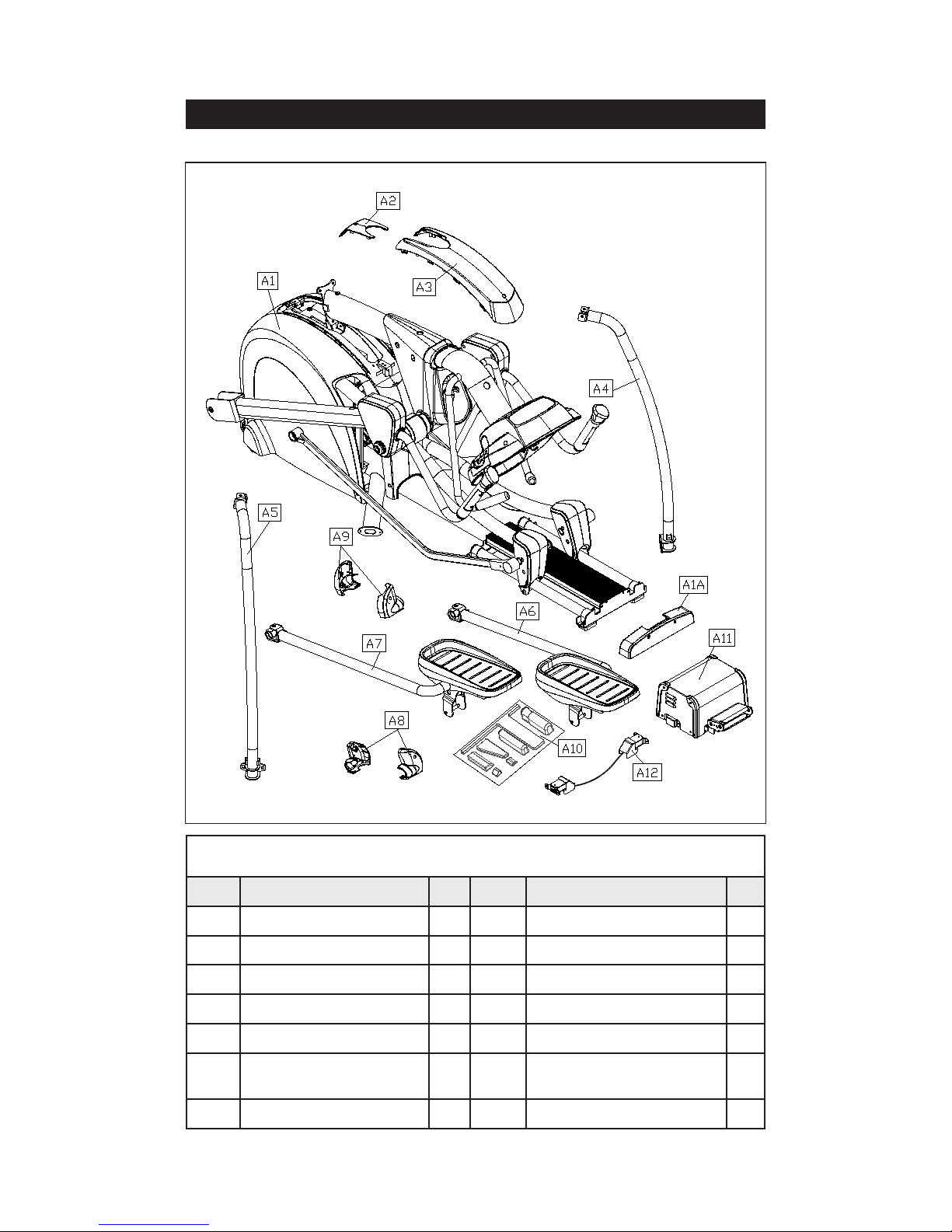
3. LIST OF PARTS
Assembly Parts
No. Name Qty. No. Name Qty.
A1 Main body 1 A7 Right footplate assembly 1
A1A Rail base cover 1 A8 Right base cover 1
A2 Small cover 1 A9 Left base cover 1
A3 Upper cover 1 A10 Hardware kit 1
A4 Right support 1 A11 Boost converter 1
A5 Left support 1 A12
Boost converter
connector cable
1
A6 Left footplate assembly 1

6
Components on the Product
No. Name Specication Notes
41 Phillips screw M5*D0.8*L10
42 Mushroom top Phillips screw M4*L16
43
Inner hex screw M8*L25
Spring washer M8
Washer D17*d8.3*t1.0
44
Inner hex screw M6*L15
Serrated washer D20*d6.2*t2.0*19T
45
Inner hex screw 5/16”*L2-1/4 inch
Seat roller washer D17*d8*t2.0
46
Roller axle
Flat washer D21*d10.5*t2
Lock nut M10
47
PU sheath D12*D8*L45
Axle M5*L71
Flat washer D10*d5.2*t1
Mushroom top inner hex screw M5*6
48 Bevelled head Phillips screw M6*P1.0*L10
Components in the Hardware Kit
No. Name Qty. Specication Notes
33 Mushroom top Phillips screw 6 M4*L16
34
Inner hex head screw 3 M8*L20
Spring washer 3 M8
Serrated washer 3 D18*d8.5*t2.0*19T
Gasket 3 D13*0.25
35 Left/right adjustment rod cover 2
36 Screw insert 4
37
M10 nut cap 2
38 Screw cap 2
L-shaped Allen wrench 1 M6
L-shaped Allen wrench 2 M4
Double open-end wrench 1 8*17
Double open-end wrench 1 13*19
T-shaped Allen wrench 1 M5
Screwdriver shank 1 at and Phillips
Screwdriver handle 1 green

7
4. ASSEMBLE THE PRODUCT
Follow instructions below to assemble this product. Note that in this manual
the words “left” and “right” are used to refer to the product and its parts. As
such, these designations correspond to the “left” and “right” sides of a person
in position to exercise on this product. Also, for brevity, the word “screws” is
used where screws, washers, and other hardware may be involved.
STEP 1 Unbox the Unit
Please follow instructions A through D to remove packaging material and to
place the unit on top of the flattened cardboard.
A. Remove the box top and the plastic sheet.
B. Start working from above, first removing Styrofoam (2) above the unit.
C. Lift Styrofoam (3) on both sides of the unit upward to remove it. Place
parts aside separately.
D. Lift the pedestal to remove Styrofoam (1) in the middle.
8
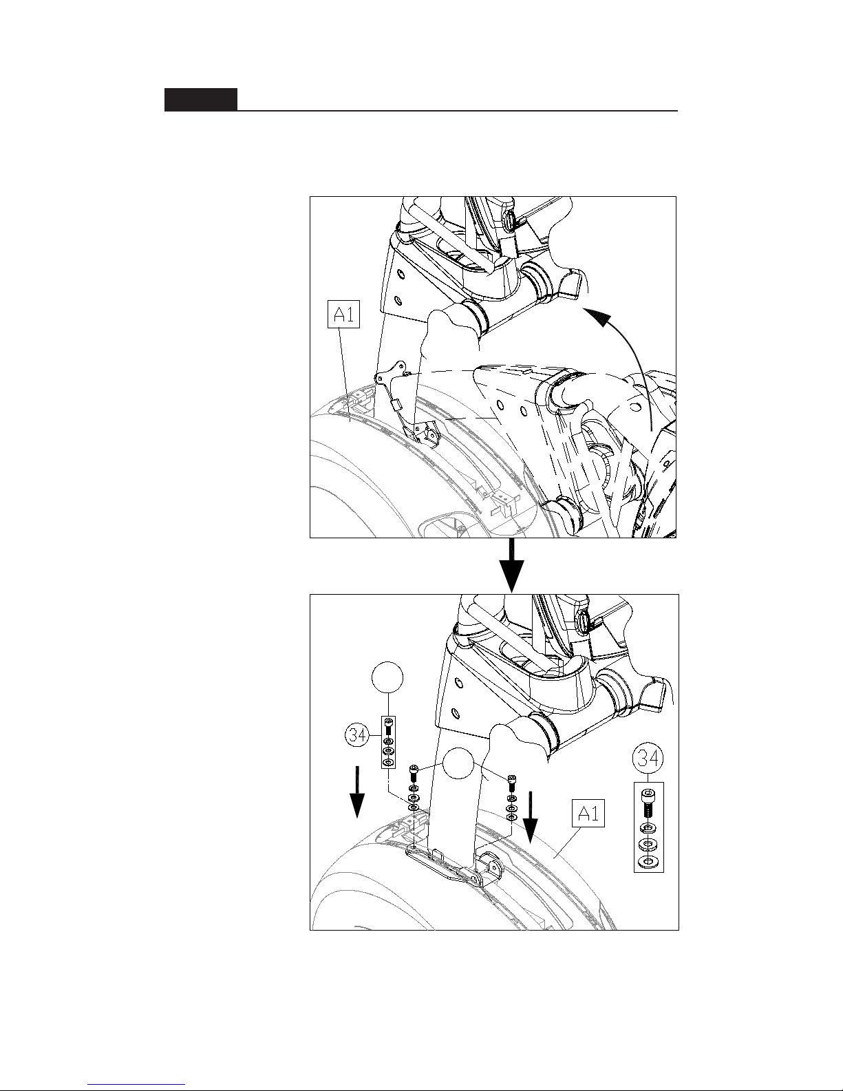
STEP 2 Assemble the Pedestal
Please follow instructions (a) through (b) to assemble the pedestal.
(a) First, lift the pedestal upright. Be careful to avoid pinching the data cable.
(b) Secure screws (34), first in area A, then in area B.
(a)
(b)
A
B

9
STEP 3 Install the Upper Cover
Please follow instructions (a) through (d) to install the upper cover.
(a) Slide the water
guard up the
pedestal. (This
ring must be
placed above the
upper cover.)
(b) Install the upper
cover and secure
it with screw (33).
(c) Install the
small cover (A2)
and secure it with
screw (33).
(d) Slide the water
guard down the
pedestal until it fits
snugly against the
covers.
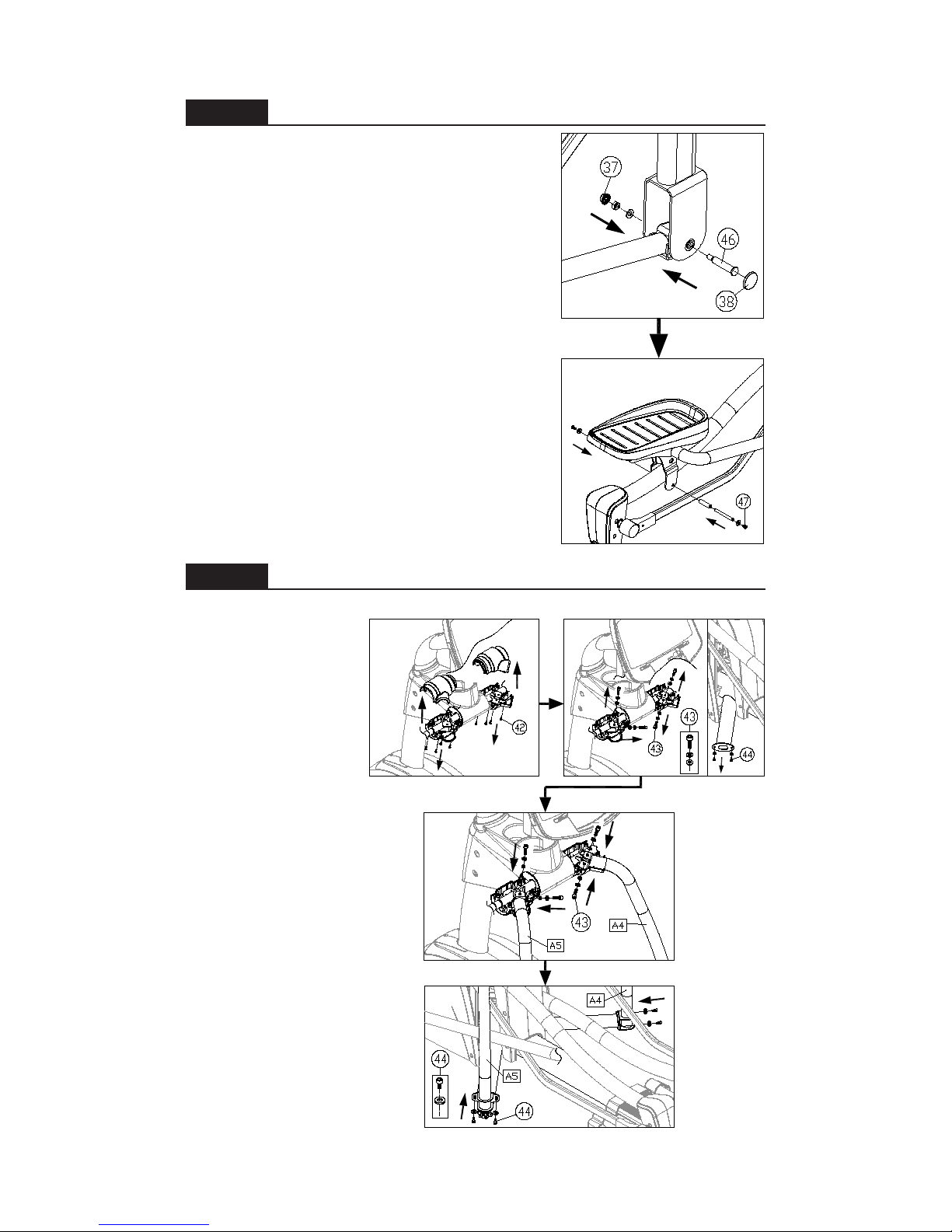
STEP 4 Install Stride Linkages and Footplate Carriages
Please follow steps (a) through (f) to install stride linkages and footplate
carriages on both sides of the product.
(a) Remove bolts (45) from the bushing on the stride adjustment mechanism.
(b) Align the hole in the stride linkage with the bushing on the stride adjustment
mechanism, and
press the stride
linkage into place
on the bushing.
Secure the stride
linkage with bolts
(45). Then insert
the stride linkage
cover (35) into
place. Follow the
same procedure
on both sides.
(c) Remove bolt
(46) from the left
footplate carriage.
(d) Remove screw
(47) from the left
footplate carriage
(A6).
(b)
(c)
(d)
(a)
(d)
(b)
(a)
(c)
10
STEP 5 Install Left/Right Supports
Please follow instructions (a) through (f) to install left and right supports.
(a) Remove screws and
remove covers from
the top of the left and
right supports.
(b) Remove screws (43)
(44) from both sides.
(c) Put left and right
supports (A4,A5) into
place and then loosely
secure screws (43) at
the top. Do not fully
secure these screws
yet.
(d) First, secure screws
(44) at the base of the
supports (A4,A5). Then
go back to the top and
secure screws (43).
STEP 4 Install Linkages/Carriages (Continued)
(e) Insert the front of the footplate carriage into
the vertical arm. Align it with the hole and use
bolt (46) to secure it into place. Then insert caps
(37, 38) into place.
(f). Lubricate the area where the rod contacts the
bushing, hold the footplate carriage into place,
and secure it with screw (47). Perform the same
actions on both sides of the product.
(e)
(f)
(d)
(c)
(b)
(a)
11
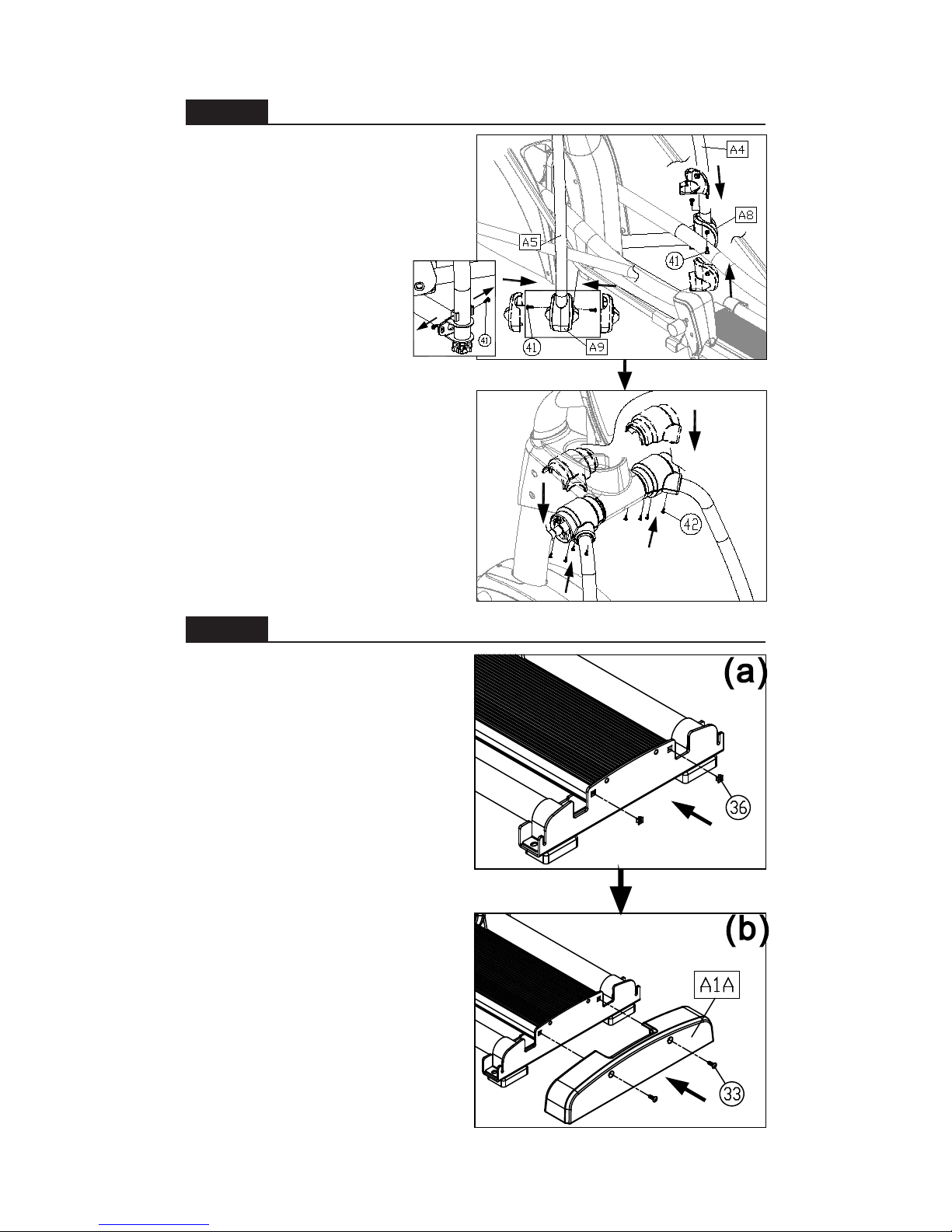
STEP 6 Secure the Rail Base Cover
Please follow instructions (a) through
(b) to install the rail base cover.
(a) First, insert screw inserts (36) into
the rail base plate.
(b) Set the rail base cover (A1A) in
place and secure it with screws (33).
STEP 5 Install Left/Right Supports (Continued)
(e) First, remove screws (41)
from the lower part of the
supports. Snap covers (A4,
A5) into place on the left and
right supports (A8, A9). Then
secure screws (41).
(f) Set upper covers into
place on both supports, and
secure them with screws
(42).
(e)
(f)
12
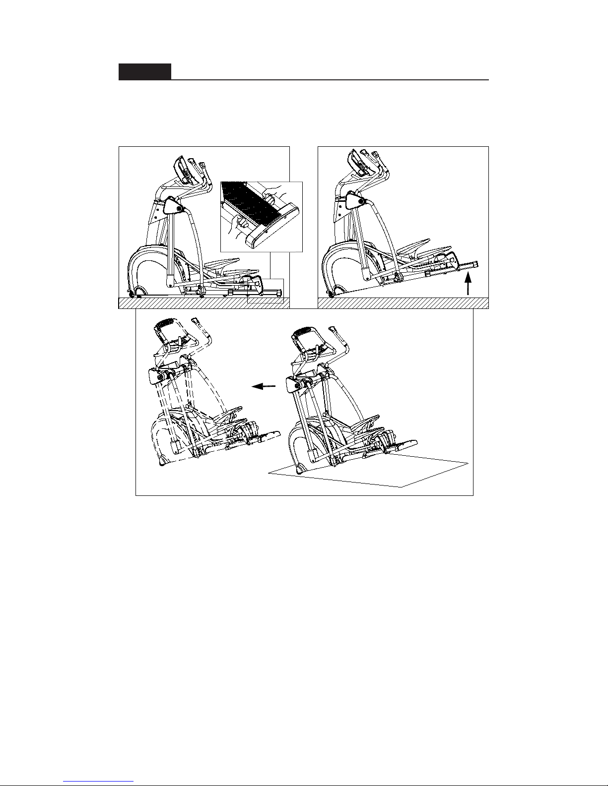
STEP 7 Move the Unit into Place
Follow steps (a) through (c) to move the unit into place for use.
(a) Stand behind the unit. Grasp the glide track rods as shown.
(b) Lift up. (To avoid injury, always use proper lifting techniques.)
(c) Push while using the transport wheels to roll the unit into place.
(b)
(a)
(c)
 Loading...