

SportsArt Fitness E870 Repair Manual

E870 Elliptical Trainer Repair Manual
SPORTS ART INDUSTRIAL CO., LTD.

【Table of Contents】
1. Component Placement
1-1-1. E870 Elliptical Trainer Unit Picture
1-1-2. E870 Components – (1) Display Area Components
1-1-3. E870 Components – (2) Back Area Components
1-1-4. E870 Components – (3) Display Board (Front)
1-1-5. E870 Components – (4) Display Board (Back)
1-1-6. E870 Components – Drive Board
1-1-7. E870 Components – Other
2. Introduction
2-1-1. E870 Introduction – Specifications
2-1-2. E870 Introduction – Display Windows
2-1-3. E870 Introduction – Display Keys and Indicators
2-1-4. E870 Introduction – Display Keys (Continued)
3. Operation
3-1-1. E870 Operation – Start Up
3-1-2. E870 Operation – Level, Stride, Fan, Stop
3-1-3. E870 Operation – Display Lock/Unlock, Clear, Program
3-1-4. E870 Operation – Basic Settings and Usage
3-1-5. E870 Operation – Lubrication Mode Operating Procedure
0-0-1

【Table of Contents】
4. Block Diagrams
4-1-1. E870 Display Board Cable Connection Block Diagram
4-1-2. E870 Drive Board Cable Connection Block Diagram
5. Cable Connections
5-1-1. E870 Display Board Cable Connection Block Diagram
5-1-2. E870 Display Board Component Placement
5-1-3. E870 Display Board Indicator Placement and Definitions
5-1-4. E870 Display Board Cable Connectors and Definitions
5-2-1. E870 Drive Board Cable Connection Block Diagrams
5-2-2. E870 Drive Board Component Placement
5-2-3. E870 Drive Board Indicator Placement and Definitions
5-2-4. E870 Drive Board Indicator Placement and Definitions (Continued)
5-2-5. E870 Drive Board Cable Connector Placement and Definitions
Continued on the following page.
0-0-2

6. Error Messages
【Table of Contents】
6-1-1. E870 Error Message: ERR7 (Continued through 6-1-3)
6-2-1. E870 Error Message: Service Battery (Continued through 6-2-3)
6-3-1. E870 Error Message: Unit will not turn on (Continued through 6-3-3)
6-4-1. E870 Error Message: Soft key malfunction (Continued through 6-4-2)
6-5-1. E870 Error Message: Telemetry heart rate malfunction (Continued through 6-5-3)
6-6-1. E870 Error Message: Heart Touch Rate malfunction (Continued through 6-6-3)
6-7-1. E870 Error Message: Resistance is too low or too high (Continued through 6-7-3)
6-9-1. E870 Error Message: No Step Count
6-8-1. E870 Error Message: Stride length does not adjust (Continued through 6-8-3)
Continued on the following page.
0-0-3

7.Testing
【Table of Contents】
7-1-1. E870 Battery Voltage Test (Continued through 7-1-2)
7-2-1. E870 Alternator Voltage Test (Continued through 7-2-2)
7-3-1. E870 Optic Sensor Voltage Test (Continued through 7-3-2)
7-4-1. E870 Stride Voltage Test (Continued through 7-4-2)
7-5-1. E870 Stride Motor Voltage Test at the Drive Board (Continued through 7-5-2)
7-6-1. E870 Electro-Magnet Voltage Test at the Drive Board (Continued through 7-6-2)
7-7-1. E870 VCC Voltage Test at the Drive Board (Continued through 7-7-2)
7-8-1. E870 VBB Voltage Test at the Drive Board (Continued through 7-8-2)
7-9-1. E870 Electro-Magnet Voltage Test at the Drive Board (Continued through 7-9-2)
7-10-1. E870 Battery Voltage Test at the Drive Board (Continued through 7-10-2)
7-11-1. E870 VBB Voltage Test at the Display Board (Continued through 7-11-2)
7-12-1. E870 VCC Voltage Test at the Display Board (Continued through 7-12-2)
7-13-1. E870 Fan Voltage Test at the Drive Board (Continued through 7-13-2)
7-14-1. E870 Remote Key Test Procedure (Continued through 7-14-2)
7-15-1. E870 HTR Cable Test (Continued through 7-15-2)
7-16-1. E870 Telemetry Heart Rate Receiver Board Test (Continued through 7-16-2)
7-17-1. E870 HTR Board Test (Continued through 7-17-2)
7-18-1. E870 Electro-Magnet Electrical Short Test (Continued through 7-18-2)
7-19-1. E870 AC Alternator Electrical Short and Open Test (Continued through 7-19-2)
7-20-1. E870 Display Board Component Placement
7-20-2. E870 Drive Board Component Placement
0-0-4

【Table of Contents】
8. Mechanical Component Adjustment and Replacement
8-2. Drive Pulley Adjustment
8-1. Rear Cover Removal Procedure
0-0-5
1. E870 Elliptical Trainer Unit Picture
1-1-1
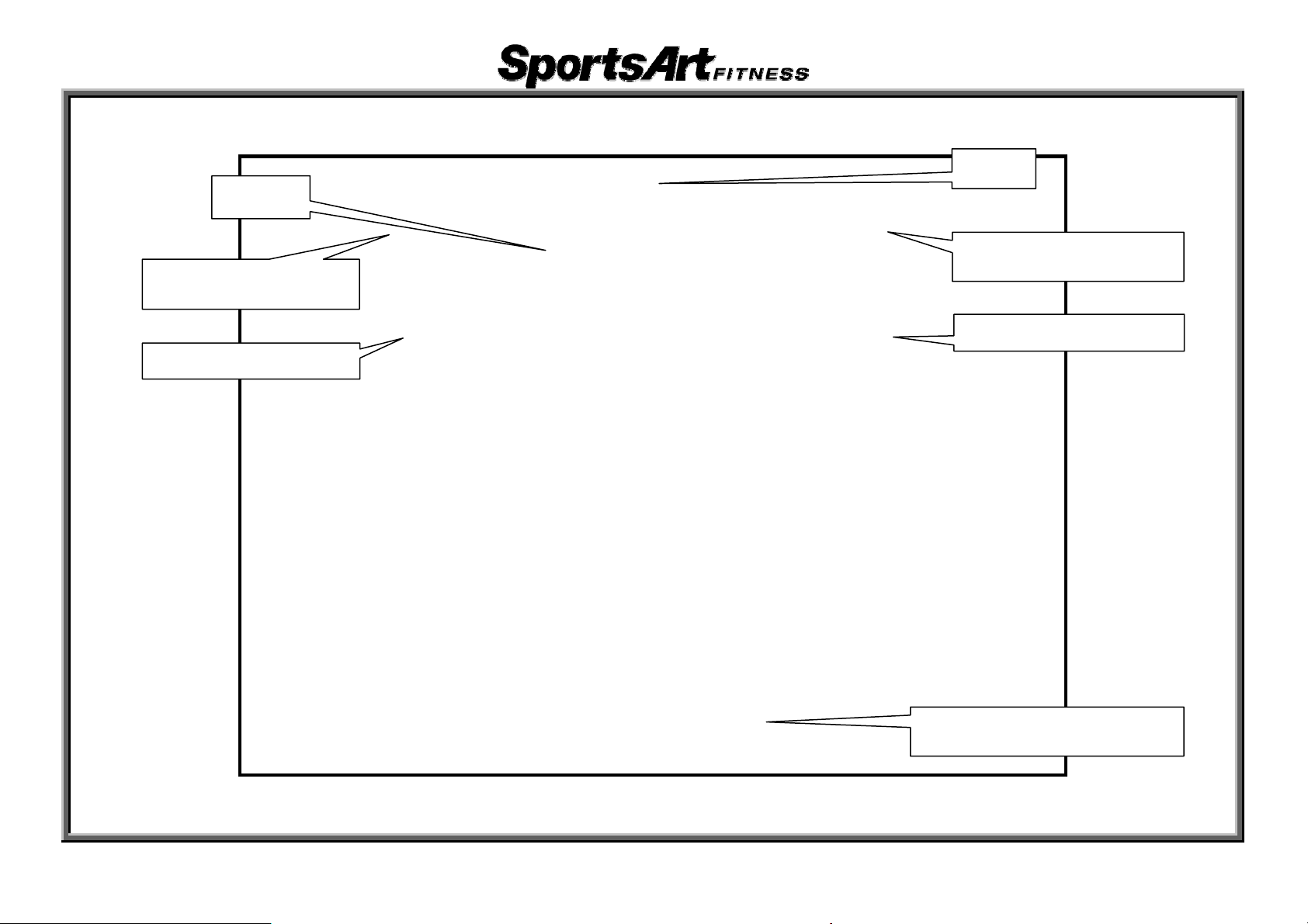
2. E870 Components – (1) Display Area Components
Display
Level Remote Key
HTR Contact (Left)
Fan
Stride Remote Key
HTR Contact (right)
1-1-2
Stride Support Assembly
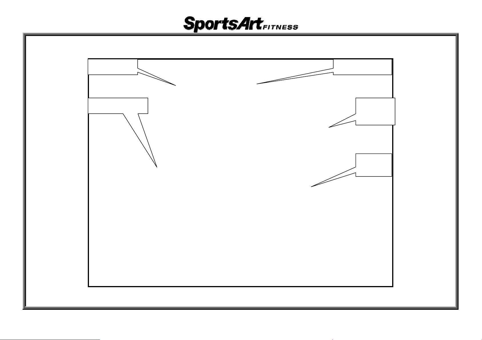
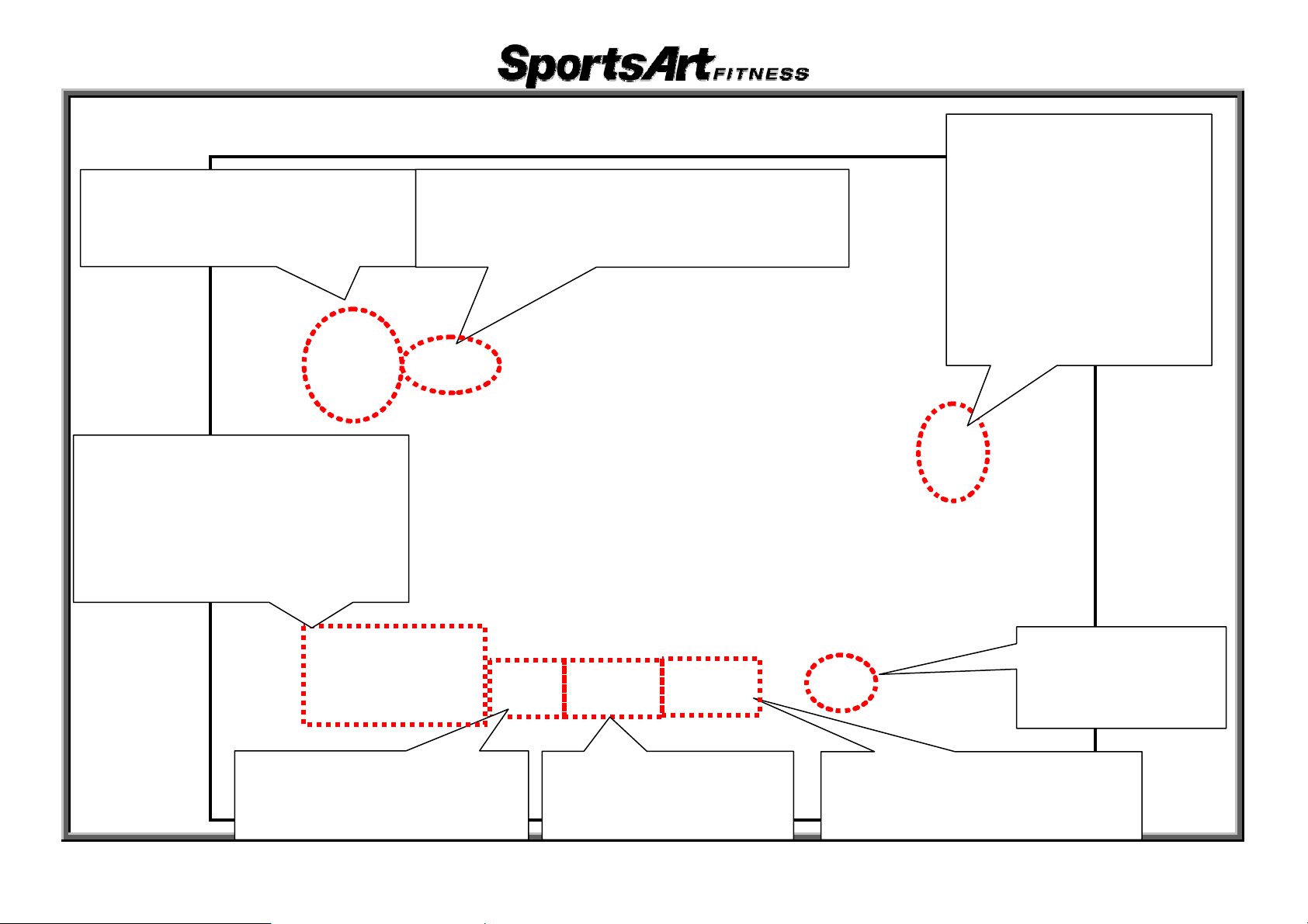
2. E870 Components-(2) Back Area Components
Batteries
Drive Board
Alternator
Electromagnet
Optic
Sensor
1-1-3

3. E870 Components – Display Board (Front)
1-1-4

3. E870 Components – Display Board (Back)
1-1-5
4. E870 Components – Drive Board
1-1-6
5. E870 Components - Others
Part Name Optic Sensor Part Name HTR Board
Part Name HRC Board
1-1-7
1. E870 Introduction - Specifications
Sp aecifications Det ils Notes
Power S AC Alter upply nator
1. Heart
Main Dis
Dot Matr
Setting 4 8-charWindow acter, 7-segment display, 1 set
Resistan 20 ce Range 1~
Stride Le ~29 in ngth 17 ch/450~730mm
Heart Ra
KPH/MP rogram H Setting P setting
Fan Sett Stop, low
Program
play Windows
ix Window
te Detection
ing -, middle- and high-speed settings
s
2.Calorie
3.Cal/
Strides
5X8 2-co
sets
16
HTR con
dete
Manual,
Burn, Va
ction
rate: 65%, 80%, Actual Heart Rate
s, Distance, Time, Strides/MIN
HR
, Stride Length, Watts, Total
lor LED square dot matrix display,
tact and telemetry strap heart rate
Random, Plateau, Interval, Fat
tride, WT Loss, Custom HR,
ri-S
Cardio
2-1-1
2. E870 Introduction – Display Windows
65% Target HR
eight loss target
ÎW
heart rate
Calories & Cal/HR Window
ÎCalories: T
ÎCal/HR: A
expenditure
Setting Window
ÎSetting values and
exercise goals
otal calories
verage calorie
Heart Rate Window
ÎActual heart rate
80% Target HR
Î Cardio traini
target heart rate
Stride/Min &Total Strides
Window
Î S
strides per minute
ÎT
count
Time & Watts Window
ÎT
ÎW
expenditure
Distance & Stride Length Window
ÎDist
ÎS
ance: Total distance
tride Length: Stride length
ng
tride/Min: average
otal Strides: Total stride
ime: Time of use
atts: Total watt
Workout Goal
ÎPercent complete
Workout Level
ÎResist
ance level
Dot Matrix Window
ÎExercise illustrations
(
2-1-2
3. E870 Introduction – Display Keys and Indicators
Exercise Goal Keys
ÎLit indi
time, distance, calories
Exercise Program Keys
ÎLit indi
Random, Plateau, Interval,
Fat Burn, Vari-Stride,
WT Loss, Cardio, Custom HR
cates exercise goal:
cates Manual,
Quick Start Key
ÎLit indicates activation of Quick S
mode
tart
Flashing indicates
heart rate reception
Display Lock/Unlock Key and
Indicator
ÎLit indi
feedback. Top: calories, distance,
time, strides/minute; Bottom:
calories/hour, stride length, Watts,
total strides
cates the active row of
2-1-3
4. E870 Introduction – Display Keys (Continued)
Exercise Goal Keys
ÎPress t
goals: time, distance, calories
Exercise Program Keys
ÎPress t
programs: Manual,
Random, Plateau, Interval,
Fat Burn, Vari-Stride,
WT Loss, Cardio, Custom HR
o select exercise
o select exercise
Quick Start Key
ÎPress to operate in Quick S
(does not require user information)
tart mode
Display Lock/Unlock Key
and Indicator
ÎPress t
feedback row. Top:
calories, distance,
time, strides/minute;
Bottom: calories/hour,
stride length, Watts,
total strides
o select active
Stop/Hold to Reset Key
ÎPress to p
present exercise mode
ause or exit
Workout Level Key
ÎPress to increase or
decrease resi
2-1-4
stance
Fan Key
ÎPress to control
Stride Length Key
ÎPress to increase or
decrease stride length
fan operation

E870 Operation
1. Start Up
Function: Press Quick Start key or exercise to start up unit.
Operation: (1) “SPORTSART – E870” scroll
“SELECT PROGRAM OR QUICKSTART” scroll
Press the Quick Start key to immediately st
key to start exercising after entering user information.
(2) PROGRAM key indicator flashes
After pressing a program key, i
program name appears for two seconds. For instance, press the <RANDOM> key;
the random program indicator lights; the message window shows “RANDOM.”
(3) WORKOUT GOAL area indicator flashes
Press either the TIME, DISTANCE, or CALORIES key to select your exerci
Either “ENTER TIME,” “ENTER DIST,” or “ENTER CALORIES” appears. Press
<▲>/<▼> or the numerical keys to set your exerci
Then press the <ENTER> key to confirm your choice.
(4) User Age and Weight Setting
“ENTER AGE” appears. Press <
goal value. Then press the <ENTER> key to confirm your choice.
(5) “ENTER WEIGHT-KG”(LB) appears. Press
set your exercise goal value. Then press the <ENTER> key to confirm your choice.
Start exercising.
s across the display. After two seconds,
s across the display.
art exercising, or press a program
ts corresponding indicator lights and the corresponding
se goal.
se goal value.
▲>/<▼> or the numerical keys to set your exercise
<▲>/<▼> or the numerical keys to
3-1-1

2. Workout Level Key
Function: Set resistance level
Operation: (1) Press the LEVEL <▲> key. The value in the Workout Level window increases.
Actual resistance increases.
(2) Press LEVEL <▼> key. The value in the Workout Level window decreases.
Actual resistance decreases.
(3) Workout level range: 1~20.
3. Stride Length Key
Function: Set stride length
Operation: (1) Press the Stride Length <▲> key. The val
The stride motor operates up. Stride length increases.
(2) Press the Stride Length <▼> key. The value in the Stride Length window decreases.
The stride motor operates down. Stride length decreases.
(3) Stride length range: KPH setting: 450-730 mm; MPH setting: 17~29 inches.
ue in the Stride Length window increases.
4. Fan Key
Function: Operate the fan
Operation: (1) Press the <FAN> key. Fan operation toggles as follows: Low -> middle -> high -> off.
(2) Display shows “FAN LOW,” “FAN MID,” “FAN HIGH,” “FAN STOP.”
(3) When no one is exerci
display.
sing on the unit, press the <FAN> key for three seconds to turn off the
5. Stop Key
Function: Exit an exercise program
Operation: (1) In exercise mode, press the<STO
(2) At any time, press the<STO
start up screen.
P>key to exit the exercise program and return to user setup.
P>key for two seconds to leave the present mode and return to the
3-1-2

6. Display Lock/Unlock Key
Function: Toggle between two rows of exercise feedback information
Operation: (1) Press the <Display Lock/Unlock> key duri
Corresponding indicators light. Top row: calories, distance, time, strides/minute. Bottom row:
Cal/hr, stride length, Watts, total strides.
(2) In scan mode (the SCAN indicator lights); the di
feedback every six seconds. In scan mode, press the <Display Lock/Unlock> key again to cancel
scan mode (the SCAN indicator extinguishes) and keep viewing the present row of feedback.
Press the <Display Lock/Unlock> key again to return to scan mode.
ng exercise to toggle between exercise feedback views.
7. Clear Key
Function: Clear setting values to 0.
Operation: Clear setting values to 0.
8. Program Key
Function: Set an exercise program.
Operation: (1) Press any exercise PROGRAM key
(2) Program keys include manual, random, plateau, interval, fat burn, vari-stride,
weight loss heart rate control, cardio heart rate control, and custom heart rate control.
. The corresponding indicator lights.
splay view toggles between the two rows of
3-1-3

9. Basic Settings and Usage Information
Function: (1) Determine basic settings (KM/MILE), see total distance and time in use, as well as
display and drive board IC versions.
Operation: (1) Press the <ENTER> key for three seconds to see basic settings.
The message window shows present settings: “UNIT - MILE” or
Press the
appears, press the
<ENTER>key to confirm your choi
key to exit this function.
(2) After you press the <ENTER> key, unit total distance appears: “DIST – XXX MILE” or “DIST –
XXXX KM”. Press the<▲/▼>keys to toggle between the two settings. When your preferred
<▲/▼>key to toggle between the two settings. When your preferred unit of measure
ce and proceed to the next setting. Or press the <STOP>
“UNIT - KM”.
unit of measure appears, press the<ENTER>key to confirm your choi
next setting. Or press the <STOP> key to exit this function.
(3) After you press the <ENTER> key, total time of use appears as
Note: the “X” shown here represents numbers.
(4) Press the <ENTER> key to proceed to the next setting. Display board IC version appears as
follows: “CTL – BE870H-1A”.
(5) Press the <ENTER> key to proceed to the next setting. Drive board IC versi
follows: “DRV – BE870-C-1A”
(6) Press the <ENTER> key to return to the start up screen or press the <STOP> key to leave the
program.
3-1-4
“TIME – XXXXXX HOUR”.
ce and proceed to the
on appears as
f
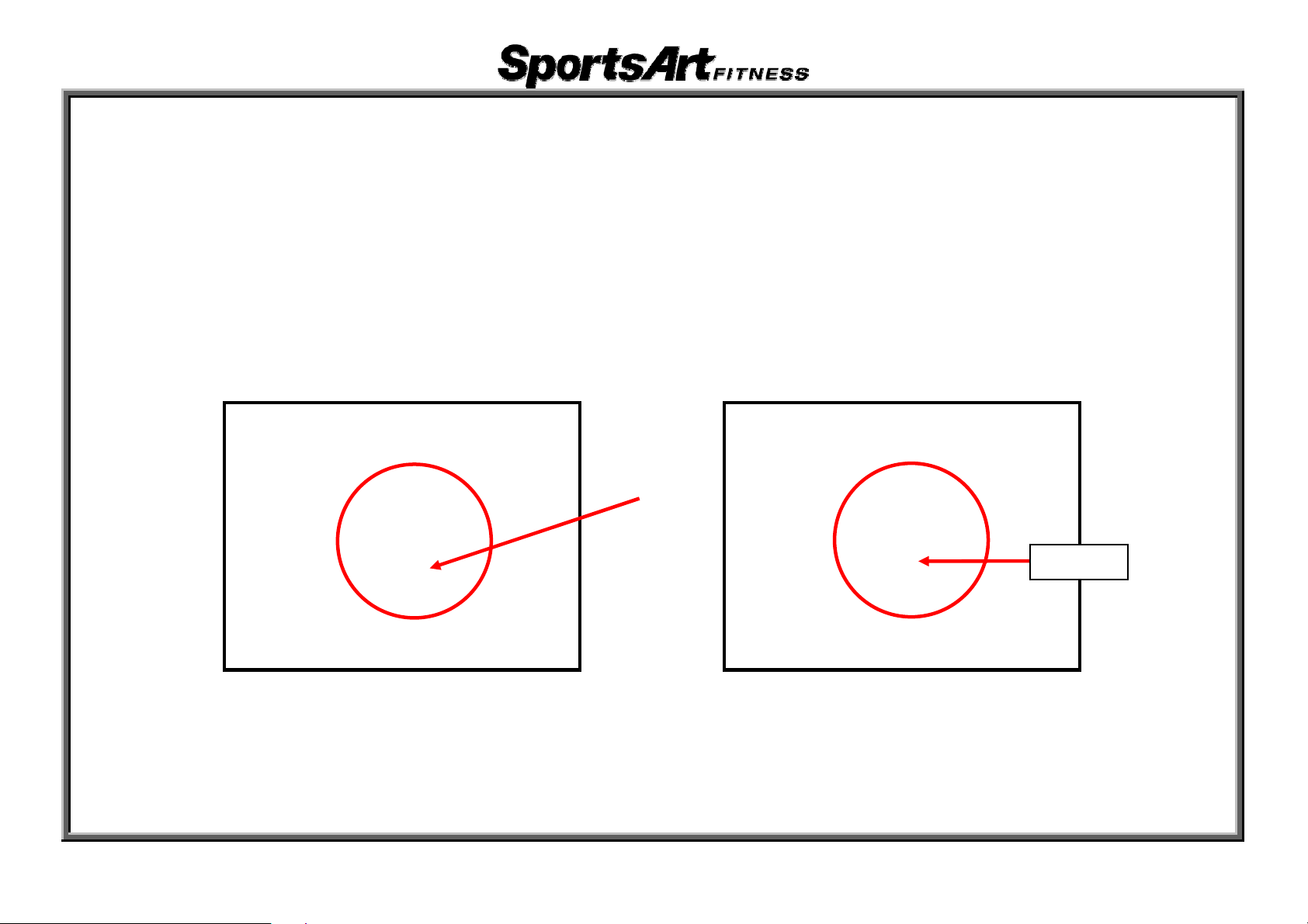
10. Lubrication Mode Operating Procedure
Function: (1) Grease the stride motor to ensure proper lubrication.
Operation: (1) At start up, when “SELECT PROGRAM OR QUICKSTART” appears, simultaneously press
<CALORIES>+<ENTER> keys for three seconds.
to allow for lubrication.
(2) “OIL” will appear in the setting window to indicate entry into the lubrication setting.
The stride motor adjusts from normal operation (Fig. 1) to the lubricati
(3) Insert a grease gun nozzle into the zi
motor. To prepare for normal operation, turn off the unit.
Fig. 1: Highest position for normal operation Fig. 2. Lubrication position (Zirc fitting appears)
rc fitting on the stride motor. Pump grease into the stride
The stride motor will automatically position itsel
on position (Fig. 2).
Zirc
3-1-5

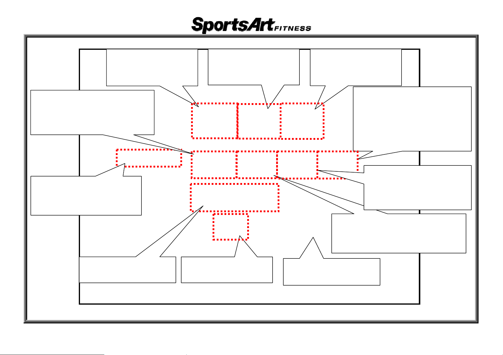
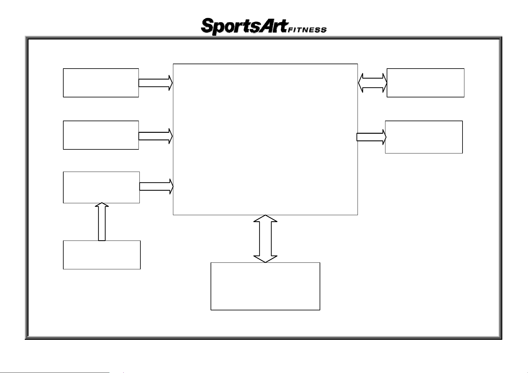
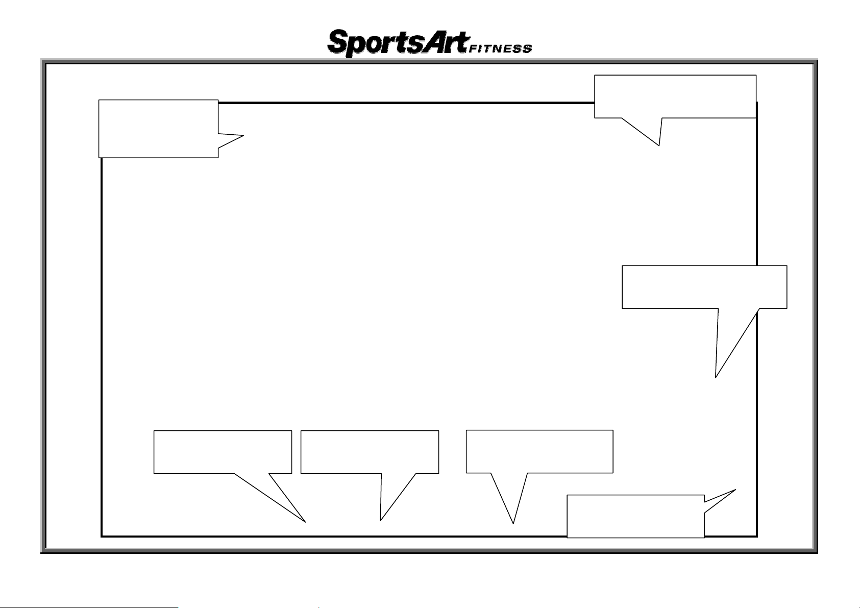
1. E870 Display Board Cable Connection Block Diagram
Keys
Telemetry Board
HTR
Board
H T R G rip (L e ft,
Right)
Display Board
C-Safe Board
Fan
Drive Board
4-1-1

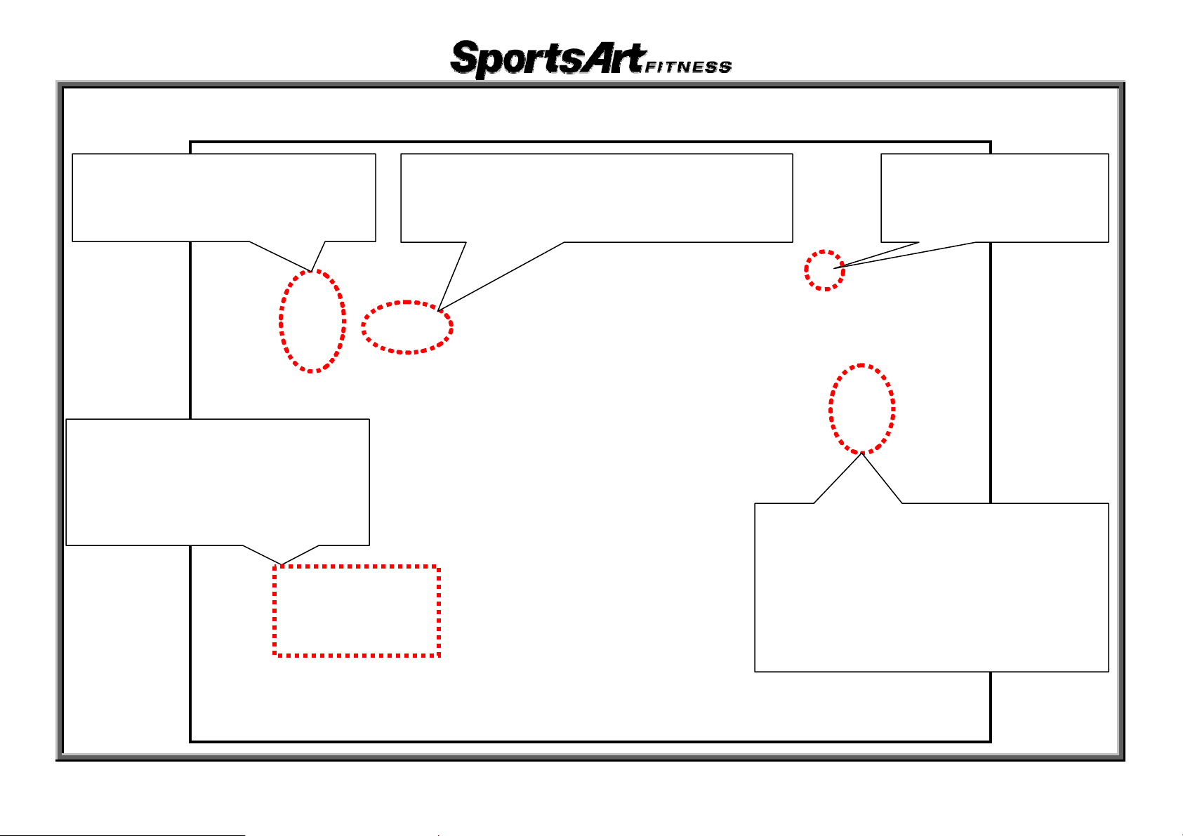
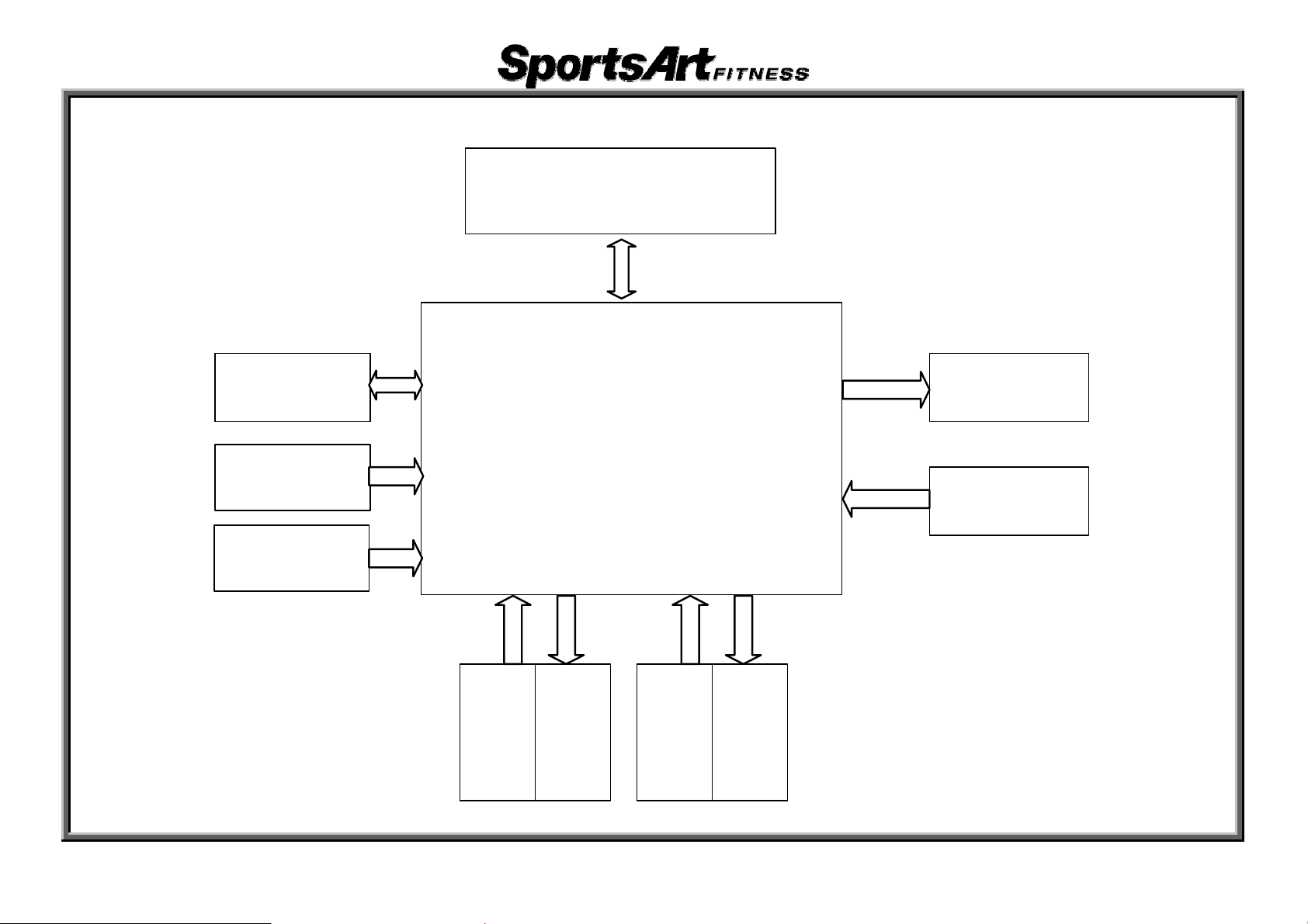
2. E870 Drive Board Cable Connection Block Diagram
Display Board
Battery
DC 30V/1.5A
Adaptor
AC Alternator
Drive Board
Left
Stride
VR
Left
Stride
Motor
Right
Stride
VR
Right
Stride
Motor
ElectroMagnet
Optic Sensor
4-1-2
1. E870 Display Board Cable Connection Block Diagram
Keys
Telemetry Board
HTR
Board
H T R G rip (L e ft,
Right)
Display Board
C-Safe Board
Fan
Drive Board
5-1-1

2. E870 Display Component Placement
5-1-2
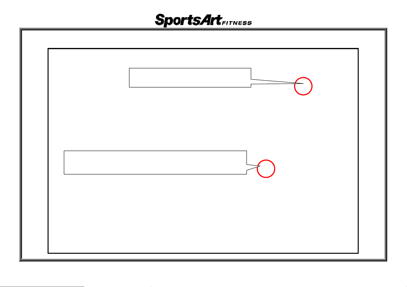
3. E870 Display Board Indicator Placement and Definitions
p
y
POWER Indicator
ÎLit indicates 5
COMM Signal Indicator
ÎFlashing indi
cates normal drive board signal processing
VDC
ower suppl
5-1-3
4. E870 Display Board Cable Connectors and Definitions
CON6
ÎT
o fan circuit
board
CON7
o 8-pin keypad
ÎT
CON8
o 13-pin keypad
ÎT
CON4
o HTR board
ÎT
CON3
ÎTo HRC board
5-1-4
CON9
o remote control
ÎT
CON5
o C-Safe board
ÎT
1. E870 Drive Board Cable Connection Block Diagram
Display Board
Battery
DC 30V /1.5 A
Adaptor
AC Alternator
Drive Board
Left
Stride
VR
Left
Stride
Motor
Right
Stride
VR
Right
Stride
Motor
Electro-
Magnet
Optic Sensor
5-2-1

2. E870 Drive Board Component Placement
5-2-2
 Loading...