

SportsArt Fitness E821, E825, E830 Repair Manual

E821/E825/E830 Elliptical Trainer Repair Manual
SPORTS ART INDUSTRIAL CO., LTD.

ȜRepair Manual Table of Contentsȝ
1. Product Component Placement Illustrations
1-1-1. E821 Product Illustration
1-1-2. E825 Product Illustration
1-1-3. E830 Product Illustration
1-1-4. E821/E825/E830 Components - (1) Display Area
1-1-5.
E821/E825/E830 Components - (2) Back Area Components
1-1-6. E821/E825/E830 Component Placement Illustrations – Display Area
1-1-7. E821/E825/E830 Component Placement Illustrations – Display Board Back
1-1-8. Electronic Component Illustrations – Drive Board
1-1-9. Electronic Component Illustrations - Other
2. Introduction
2-1-1. E821/E825/E830 Specifications
2-1-2. E821/E825/E830 Display Functions
2-1-3. E821/E825/E830 Display Functions (Indicator LEDs)
2-1-4. E821/E825/E830 Display Functions (Keys)
3. Operation
3-1-1. E821/E825/E830 Display Operation

ȜRepair Manual Table of Contentsȝ!
!
4. Unit Block Diagrams
4-1. E821/E825/E830 Display Board Cable Connection Block Diagram
4-2. E821/E825/E830 Drive Board Cable Connection Block Diagram
5. Cable Connection Illustrations
5-1-1. E821/E825/E830 Display Board Wire Connections
5-1-2. E821/E825/E830 Display Board Component Placement
5-1-3. E821/E825/E830 Display Indicator LEDs
5-1-4. E821/E825/E830 Display Cable Connections
5-2-1. E821/E825/E830 Drive Board Operation Flow Chart
5-2-2. E821/E825/E830 Drive Board Indic
tor LED Placement and Definitions
5-2-3. E821/E825/E830 Drive Board Indicator LED Placement and Definitions
5-2-4. E821/E825/E830 Drive Board Wire Connection Placement and Definitions

ȜRepair Manual Table of Contentsȝ
6. Error Messages
6-1. ERR7
6-2. Unit Does Not Turn On
6-3. Key Malfunction
6-4. Telemetry Heart Rate Malfunction
6-5. HTR Heart Rate Malfunction
6-6. Resistance Malfunction
6-7. No Stride Operation
7. Electronic Component Testing
7-1. Optic Sensor Test
7-2. Transformer Electrical Short/Open Test
7-3. Stride Motor Voltage Test at Drive Board
7-4. VCC Voltage Test at Drive Board
7-5. VDD Voltage Test at Drive Board
7-6. Electro-Magnet Voltage Test at Drive Board
7-7. Display Key Switch Test
7-8. Display VBB Voltage Test
7-9. Display VCC Voltage Test
7-10. Display LED Voltage Test
7-11. Telemetry Heart Rate Reading Test
7-12. HTR Board Test

ȜRepair Manual Table of Contentsȝ
7-13. HTR Heart Rate Handlebar Test
7-14. Transformer Short/Open Test
7-15. Electro-Magnet Short/Open Test
8. Mechanical Adjustments and Part Replacement
8-1. E821/E825/E830 Procedure to Remove Rear Covers
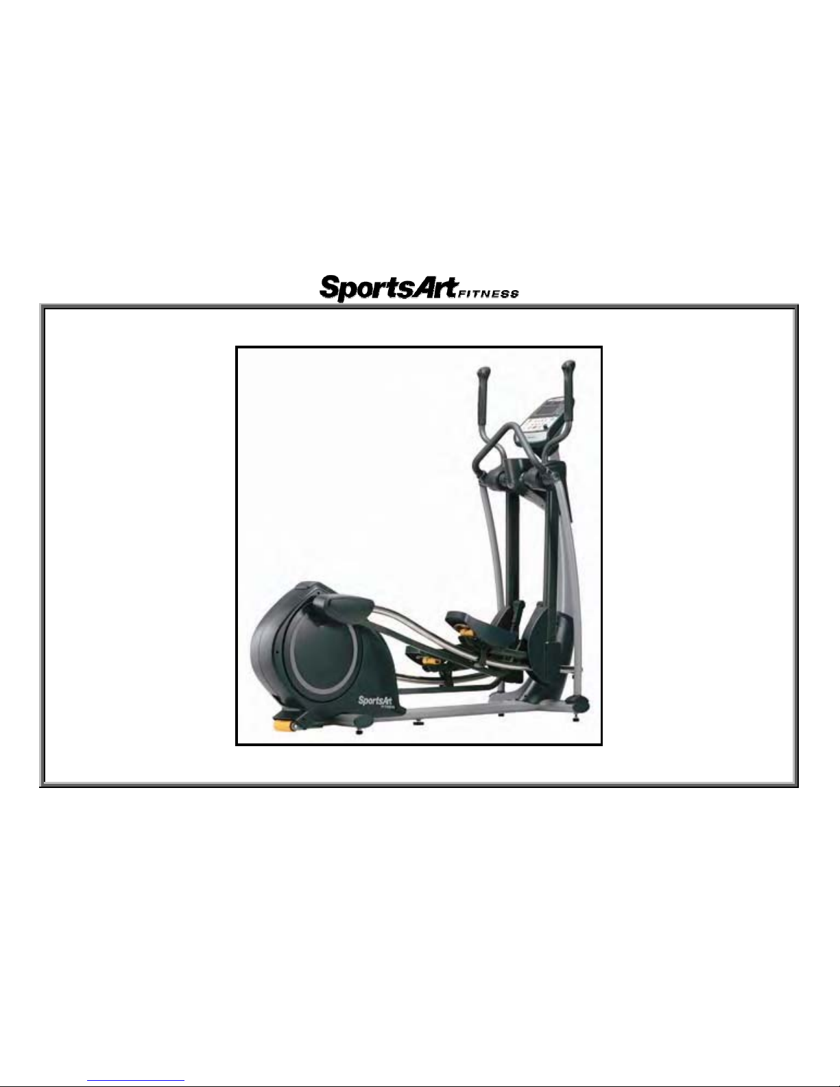
1.E821 Elliptical Trainer Unit Picture
1-1-1
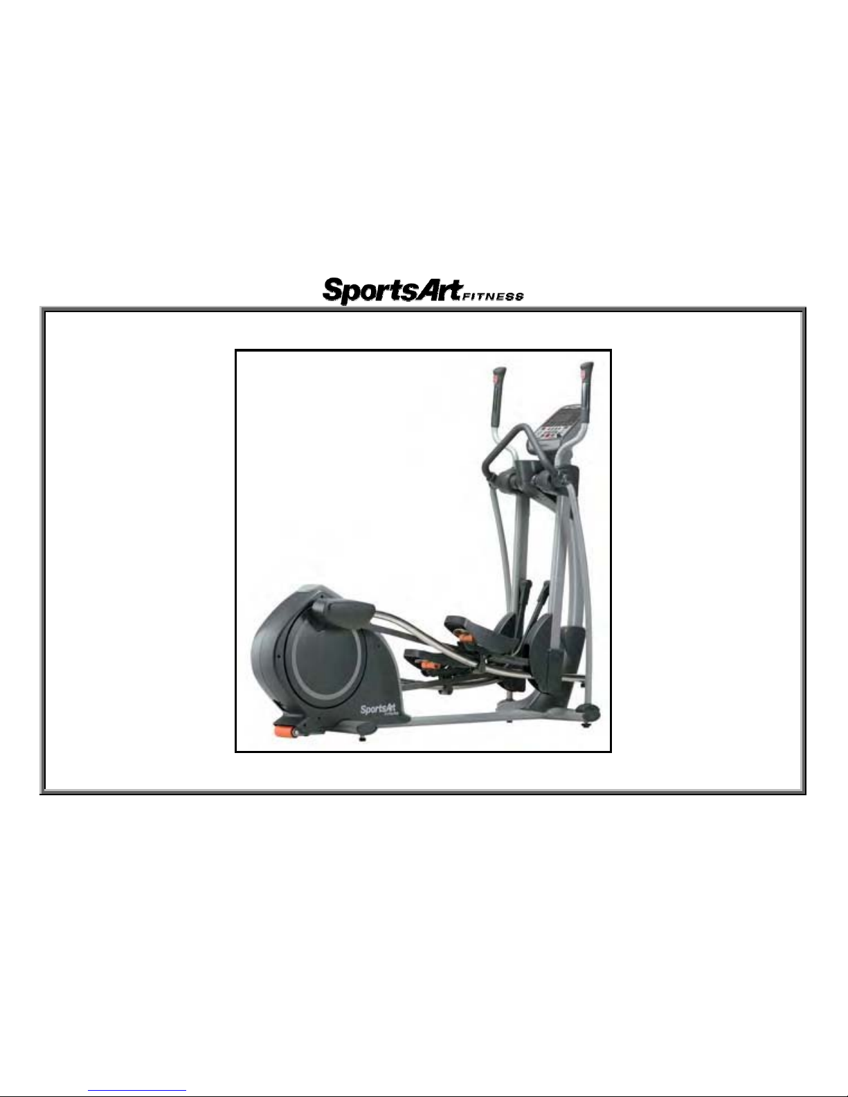
2.E825 Elliptical Trainer Unit Picture
1-1-2

3.E830 Elliptical Trainer Unit Picture
1-1-3
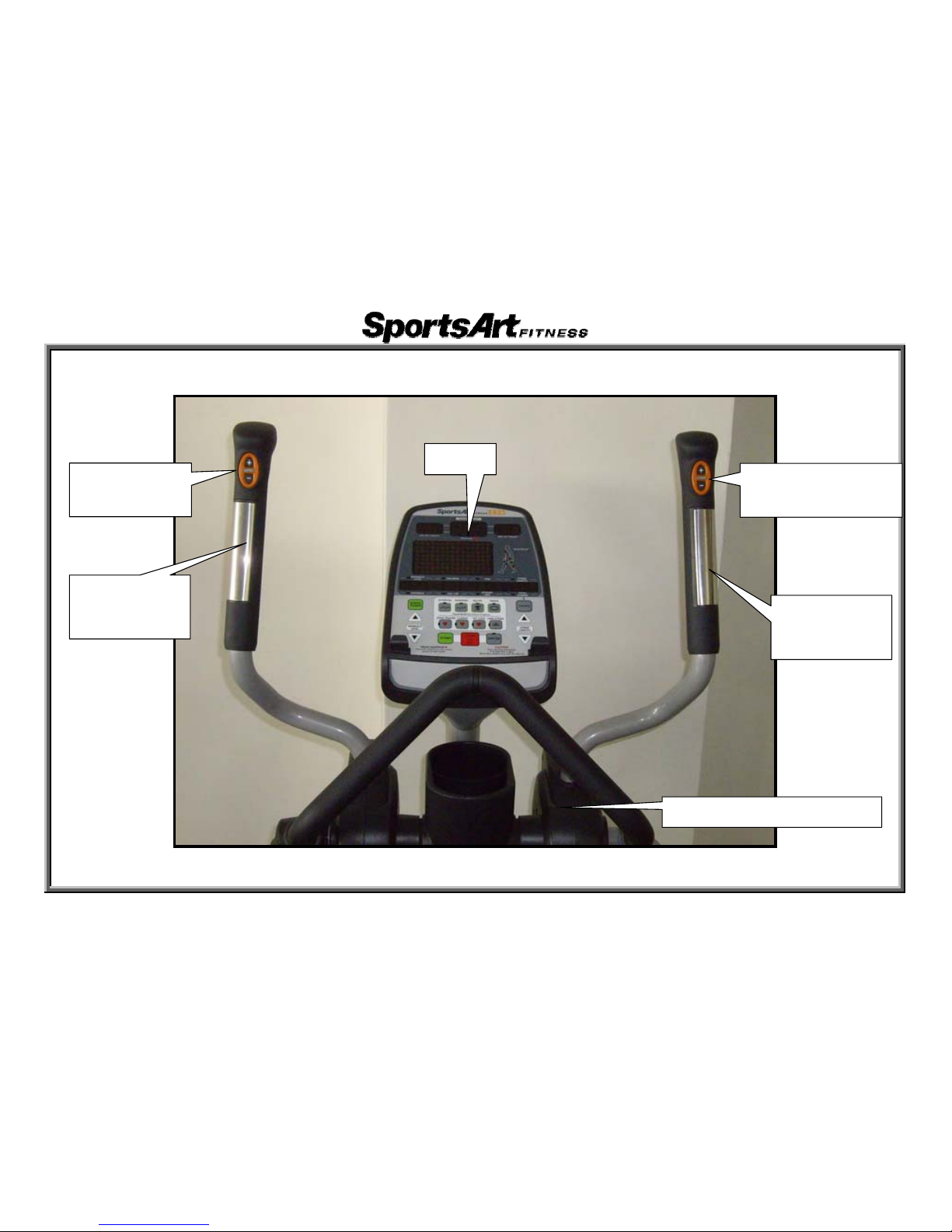
4.E821/E825/E830 Components ɡ (1) Display Area
Display
LEVEL Key
(Not on E821)
STRIDE key
(Not on E821)
HTR Contact
(Left)
(Not on E821)
HTR contact
(Right)
(Not on E821)
Stride Adjustment Motor
1-1-4
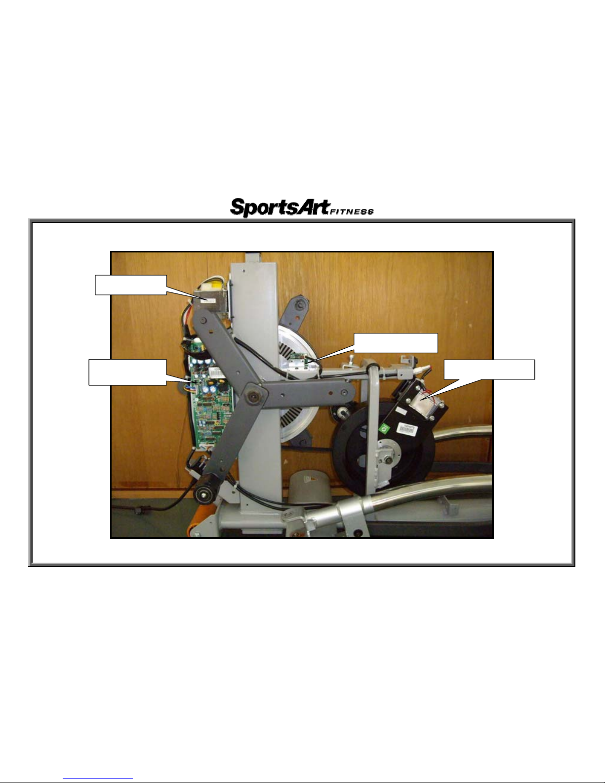
5.E821/E825/E830 Componentsɡ(2) Back Area Components
Transformer
Electro-magnet
Optic Sensor
Drive Board
1-1-5
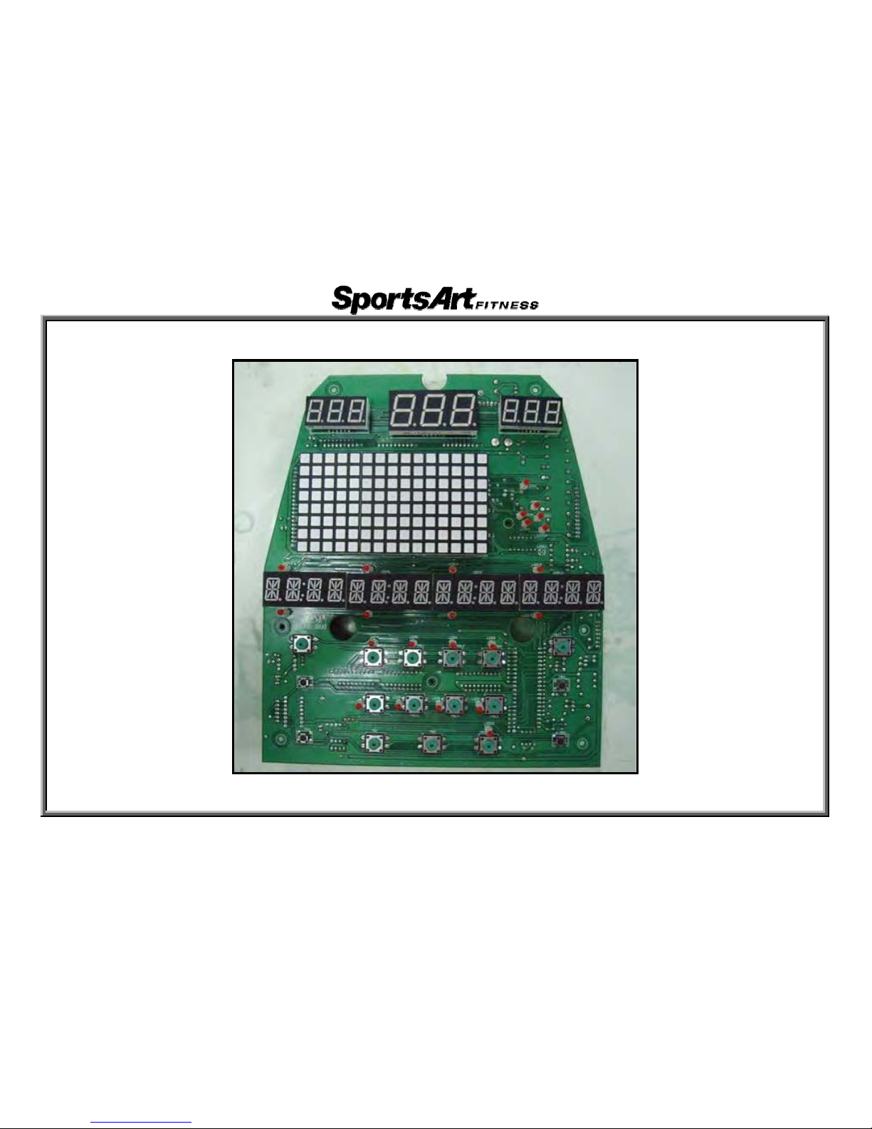
3.E821/E825/E830 Components – Display Board (Front)
1-1-6
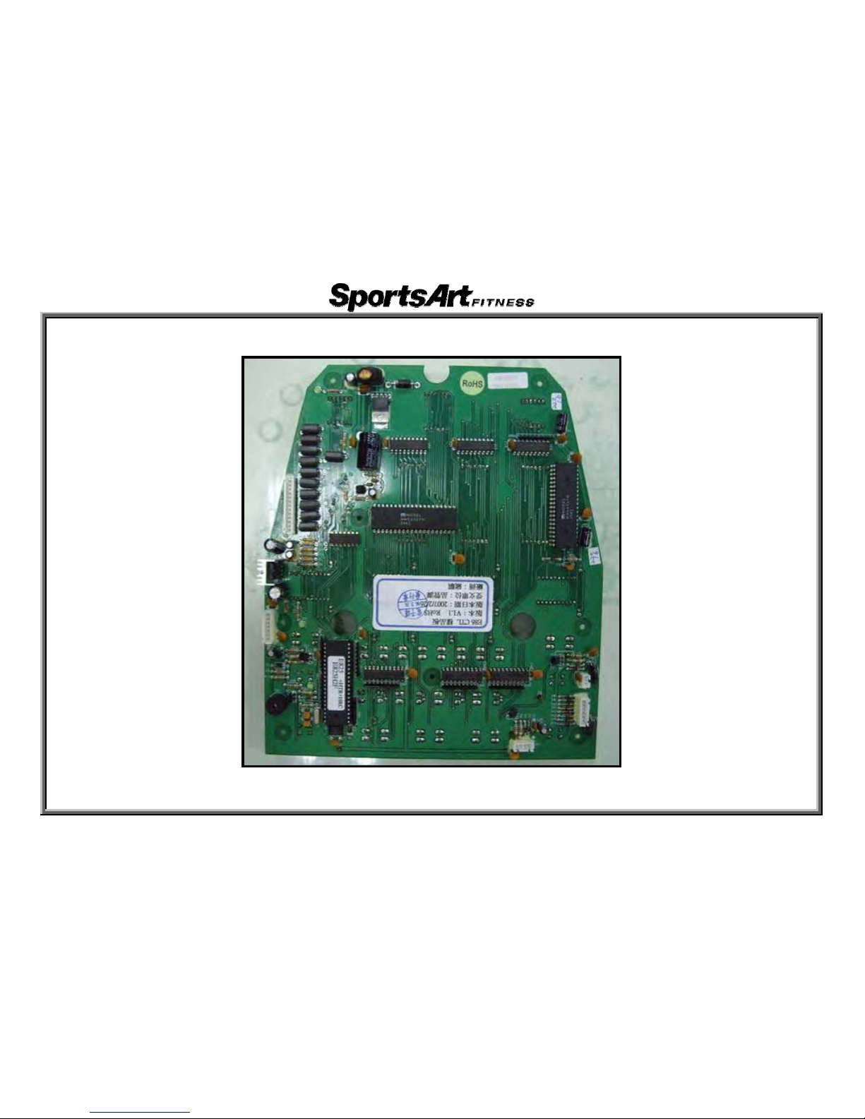
3.E821/E825/E830 E870 Components – Display Board (Back)
1-1-7
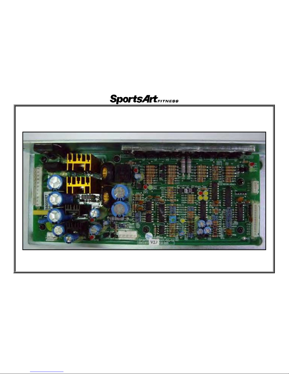
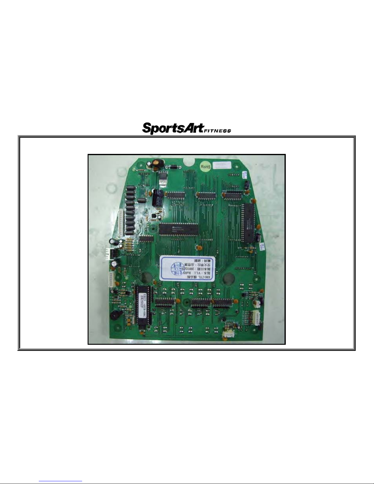
3.E821/R825/R830 Components – Drive Board
1-1-8
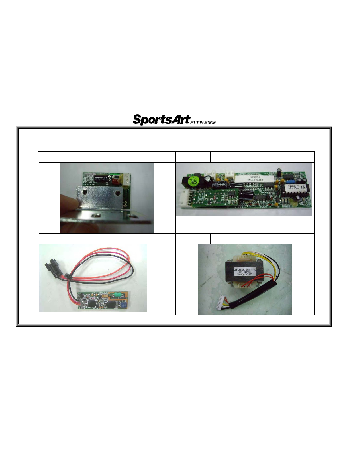
3.E821/E825/E830 Components - Others
Part Name Optic Sensor Part Name HTR Board
Part Name HRC Board Part Name Transformer
1-1-9
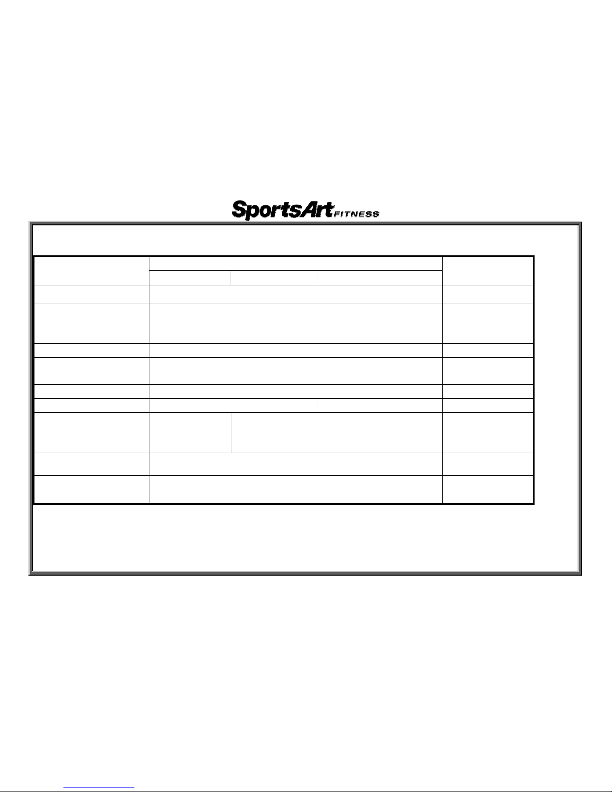
1.E821/E825/E830 Specification Chart
!!! Contents Spe
Not
cification
E821 E825 E830
es
Pow ACer 110V/220V
Mai
1.H
2.W
3.Di
n Window
RC window: 65%, 80%, Heartrate
orkout level, Calories , Time , Stride Length ,
stance, Cal/HR, Strides/MIN, Total Strides
Illus X8tration Window 5 Bi-color LED dot matrix 16 set
Sett
se
disp
ing Window
1 t of four 8-character seven segment character
lays
Res 1~2istance 0
STR 7~ 17~IDE LENGTH 1 26inch/450~650mm 29inch/450~730mm
Hea
Tele
rt Rate Detection
(wir
rate
metry
eless) heart
reception
hea
HTR (contact) and telemetry (wireless)
rt rate reception
KP DetH/MPH Setting ermined by the IC program
Wor
Tra
T
kout Programs
W
ck Glute, Random , Interval, Vari-Stride
Loss, Cardio, Zone Trainer
2-1-1
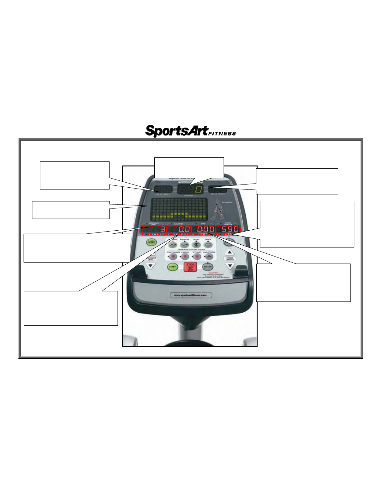
2.E821/E825/E830 Introduction – Display Windows
(
Heart Rate Window
ÎActual heart rate
80% Target HR
Î Cardio traini
ng target
heart rate
65% Target HR
ÎW
eight loss target
heart rate
Dot Matrix Window
ÎExercise illustrations
Workout Level & Distance Window
Î Wo
rkout LevelǺResistance level
ÎDistanceǺT
otal distance
Calories & Cal/HR Window
ÎCalories
ǺTotal calories
ÎCal/HRǺA
verage calorie
ex
p
enditure
Stride Length &Total Strides
Window
Î S
tride Length: Stride length
ÎT
otal StridesǺTotal stride
count
Time & Stride/Min Window
ÎTi
meǺTime of use
Î St
ride/MinǺaverage strides
per minute
2-1-2
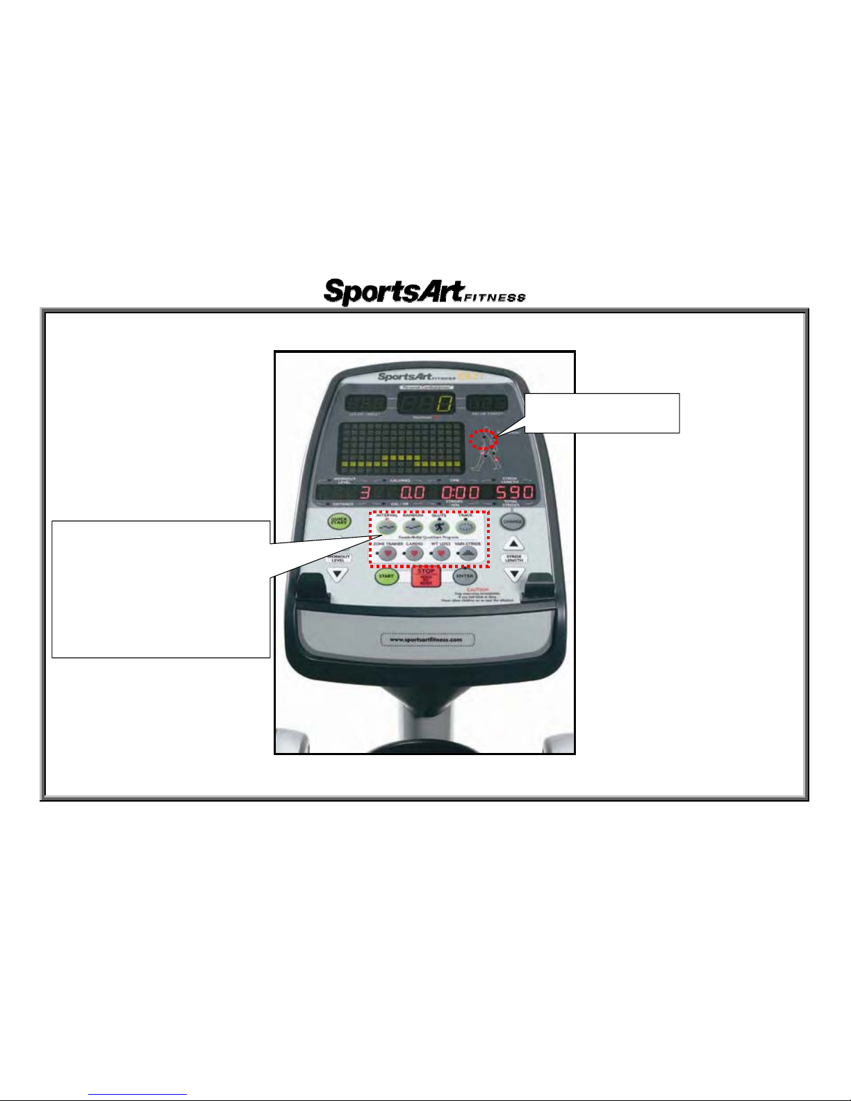
3. E821/E825/E830 Introduction – Display Keys and Indicators
Flashing indicates
heart rate rece
p
tion
Exercise Program Keys
Î Lit indicates!
Usbdl-Hmvuf-Sboepn-!
Joufswbm-WBSJ.TUSJEF!!
Wbsj.Tusjef-!
XU!Mptt-Dbsejp-!
[POF!USBJOFS ኳԄ!
2-1-3
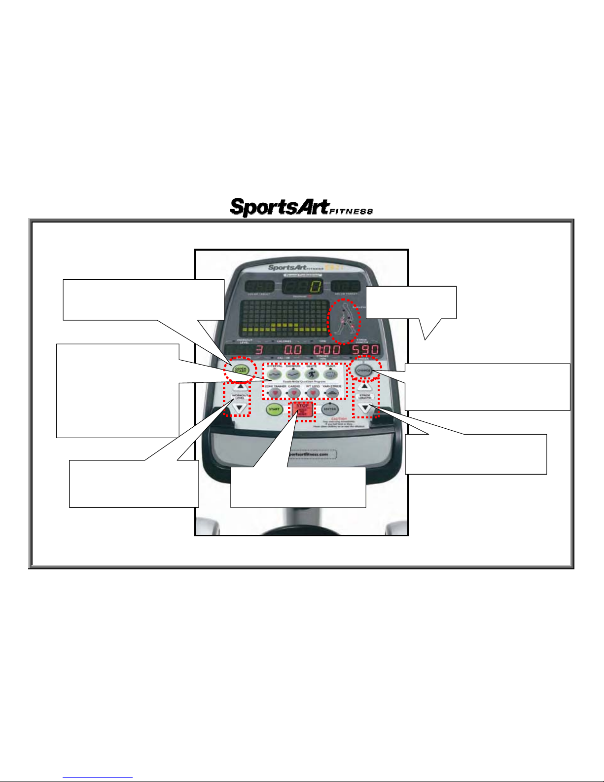
4.E821/E825/E830 Introduction – Display Keys (Continued)
Exercise Program Keys
ÎPress t
o select
exercise!
Usbdl-Hmvuf-Sboepn-!
Joufswbm-WBSJ.TUSJEF!!
Wbsj.Tusjef-!
XU!Mptt-Dbsejp-!
Display Lock/Unlock Key and
Indicator
ÎPress t
o select active feedback
Stride Length Key
ÎPress to increase or
decrease stride len
g
th
ၮҞࡪᗖ
ÎᒧၮҞ
Quick Start Key
ÎPress to operate in Quick S
tart
mode (does not require user
Stop/Hold to Reset Key
ÎPress to p
ause or exit
present exercise mode
Workout Level Key
ÎPress to increase or
decrease resi
stance
2-1-4

E821/E825/E830 Operation
1. Start Up
Function: Turn and start operating unit.
Operation: (1) Turn on unit. Display shows
“SPORTSART – E8XX”.
After 6 seconds, “PRESS START” scrolls across the display.
Press the QUICK START key to directly begin exercising, or press the PROGRAM key
to establish user settings.
(2) The PROGRAM indicator flashes.
After a program key is pressed, the associated LED lights. The feedback window shows
characters 2 seconds. Press the <RANDOM> key. The RANDOM LED lights. The feedback window shows “RANDOM”.
(3) Age and Weight Setting
When the screen shows “ENTER AGE”, enter age value, then press the <ENTER> key to confirm your choice.
When the display shows “ENTER WEIGHT-KG”OR”LB“, enter your weight value, then press the <ENTER> key to
confirm your choice.
(4) The unit can now be operated.
3-1-1

2. Workout Level Key
Function: Set resistance level
Operation: (1) Press the LEVEL <> key. The value in the Workout Level window increases.
Actual resistance increases.
(2) Press LEVEL <> key. The value in the Workout Level window decreases.
Actual resistance decreases.
(3) Workout level range: 1~20.
3. Stride Length Key
Function: Set stride length
Operation: (1) Press the Stride Length <> key. The val
ue in the Stride Length window increases.
The stride motor operates up. Stride length increases.
(2) Press the Stride Length <> key. The value in the Stride Length window decreases.
The stride motor operates down. Stride length decreases.
(3) Stride length range: E821/E825 KPH setting: 450-650 mm; MPH setting: 17~26 inches.
E830 KPH
setting: 450-730 mm; MPH setting: 17~29 inches.
4. Stop Key
Function: Exit an exercise program
Operation: (1) In exercise mode, press theɦSTO
Pɧkey to exit the exercise program and return to user setup.
(2) At any time, press theɦSTOPɧkey for two seconds to l
eave the present mode and return to the
start up screen.
3-1-2

5. Display Lock/Unlock Key
Function: Toggle between two rows of exercise feedback information
Operation: (1) Press the <Display Lock/Unlock> key duri
ng exercise to toggle between exercise feedback views.
Corresponding indicators light. Top row: calories, distance, time, strides/minute. Bottom row:
Cal/hr, stride length, Watts, total strides.
(2) In scan mode (the SCAN indicator lights); the di
splay view toggles between the two rows of
feedback every six seconds. In scan mode, press the <Display Lock/Unlock> key again to cancel
scan mode (the SCAN indicator extinguishes) and keep viewing the present row of feedback.
Press the <Display Lock/Unlock> key again to return to scan mode.
6. Program Key
Function: Set an exercise program.
Operation: (1) Press any exercise PROGRAM key
. The corresponding indicator lights.
(2) Program keys include TRA
CKǵGLUTEǵRANDOMǵINTERVALǵVARI-STRIDEǵ weight loss heart
rate control, cardio heart rate control, and custom heart rate control.
3-1-3

7. Basic Settings
Function: (1) KM/MILE setting, total distance, time, display and drive board versions.
Operation: (1) Press and hold the <ENTER> key for three seconds to enter the setting mode.
Unit settings appear. American standard appears as
“UNIT - ML”. Metric standard appears as ”UNIT - KM”.
Press the ɦ/ɧ keys to toggle between settings. Press theɦENTERɧkey or press the <STOP> key to exit this
setting.
(2) Press the <ENTER> key to confirm your choice and view total time of operation: “TIME – XXXXXX HOUR”.
(3) Press the <ENTER> key to proceed to the next step and view total mileage. In the American standard setting,
“DIST – XXX ML” appears. In the metric setting, ”DIST – XXXX KM” appears. Pressɦ/ɧkeys to toggle between
the two settings.
(4) Press the <ENTER> key to confirm your choice and proceed to the USER setting. The feedback window shows
“PRESS UP/DN TO ACTIVATE OR DEACTIVATE 4 USER SETTING”. Press theɦ/ɧkeys to toggle between
the following: “USER ID - ON” (allows 4 user settings); “USER ID - OFF” (deactivates user settings).
(5) Press the <ENTER> key to proceed to see the display version. The feedback window shows “E8XXH-XX”.
(6) Press the <ENTER> key to complete settings and return to the start up screen.
3-1-4
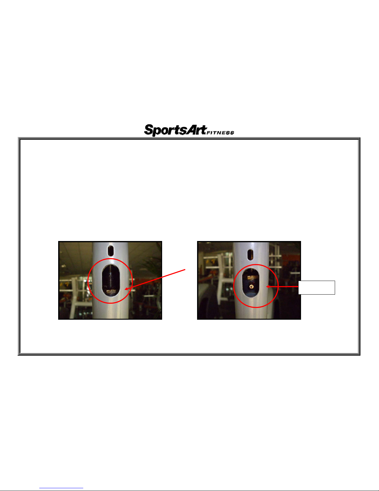
8. Stride Motor Lubrication Procedure
Function: (1) Lubricate the stride motor.
Operation: (1) As
“SPO
RTSART-E8XX” scrolls across the display, simultaneously press and hold
<
STRIDE LENGTH>+<STRIDE LENGTH>+<INTERVAL> keys for three seconds to enter
the lubrication procedure.!!!!!!
(2) Upon enteri
ng the lubrication mode, the stride motor immediately operates, aligning itself with the
oil hole. “FILLI
NG WITH LUBRICANT” scrolls across the display. Prior to entering the
lubrication mode, the stride adjustment arm appears as shown in Fig. 1. After the stri
de motors
move to the lubrication position, the stride adjustment arm appears as shown in Fig. 2.
(3) Insert a grease gun onto the Zirc fitting in the product. Squeeze the grease gun two to three
times. After applying lubricant, press the <STOP> key to exit the lubrication mode and return to
the start up screen.
Fig. 1. Normal stride motor operation position Fig. 2. Lubrication mode stride motor position
Zirc fitting
3-1-5
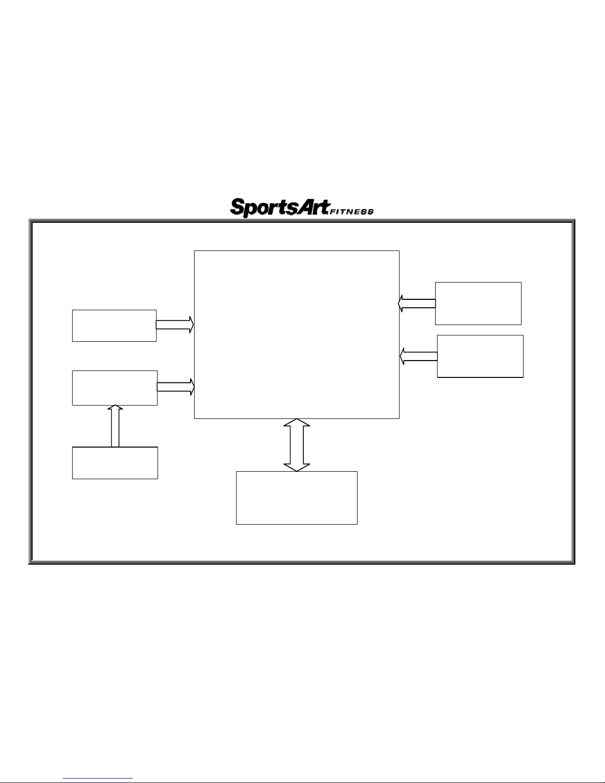
1. E821/E825/E830 Display Board Cable Connection Block Diagram
Display Board
HTR
Board
Stride Motor VR
(Left/Right)
Telemetry
Transmitter
HTR Contact
(Left, Right)
Drive Board
(E825/
E830)
(E825/
E830)
Resistance/
Stride Keys
4-1-1
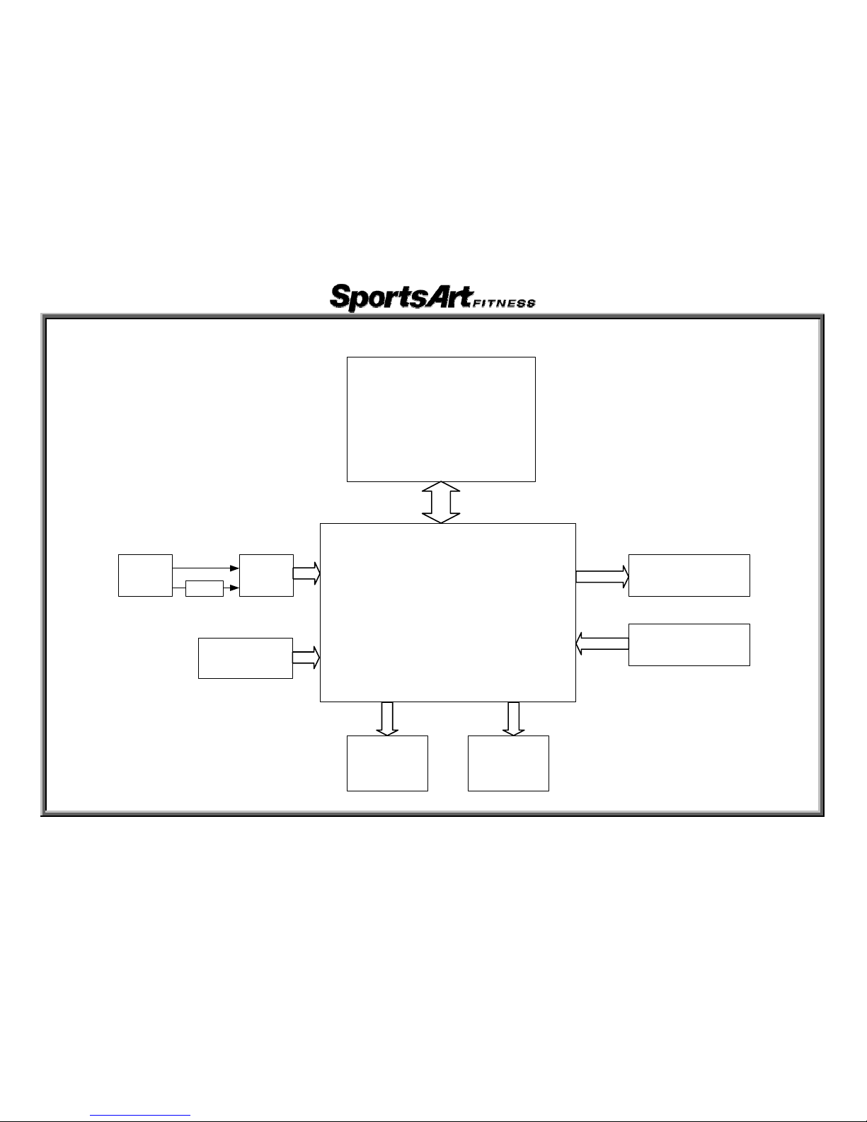
2. E821/E825/E830 Drive Board Cable Connection Block Diagram
Display Board
Drive Board
Optic Sensor
Electro-Magnet
Left Stride
Motor
On/Off
Switch
Transformer
Power
Cord
Right Stride
Motor
FUSE
4-1-2
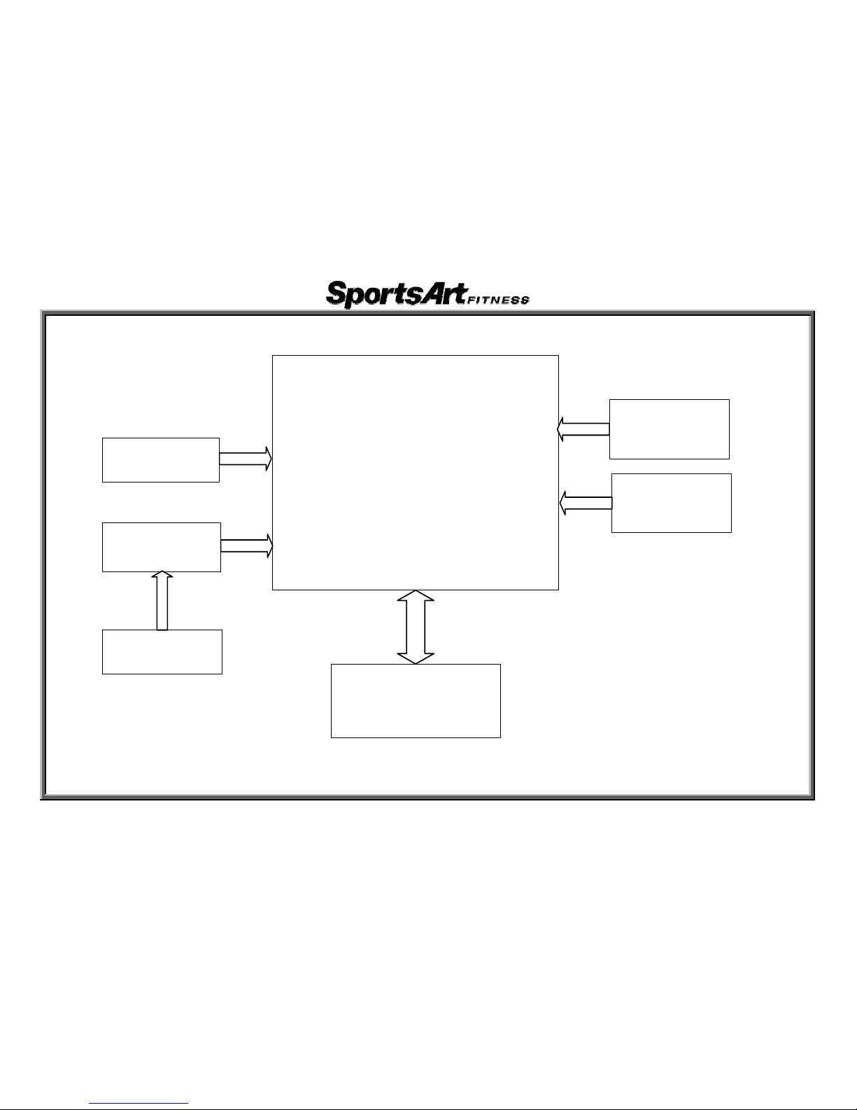
1. E821/E825/E830 Display Board Wire Connections
Display Board
HTR Board
Stride VR (Left/
Right)
POLAR
HTR Grip (Left/
Right)
Drive Board
(E825/
E830)
(E825/
E830)
Resistance/
Stride Keypad
5-1-1
2. E821/E825/E830 Display Board Component Placement
5-1-2
 Loading...