

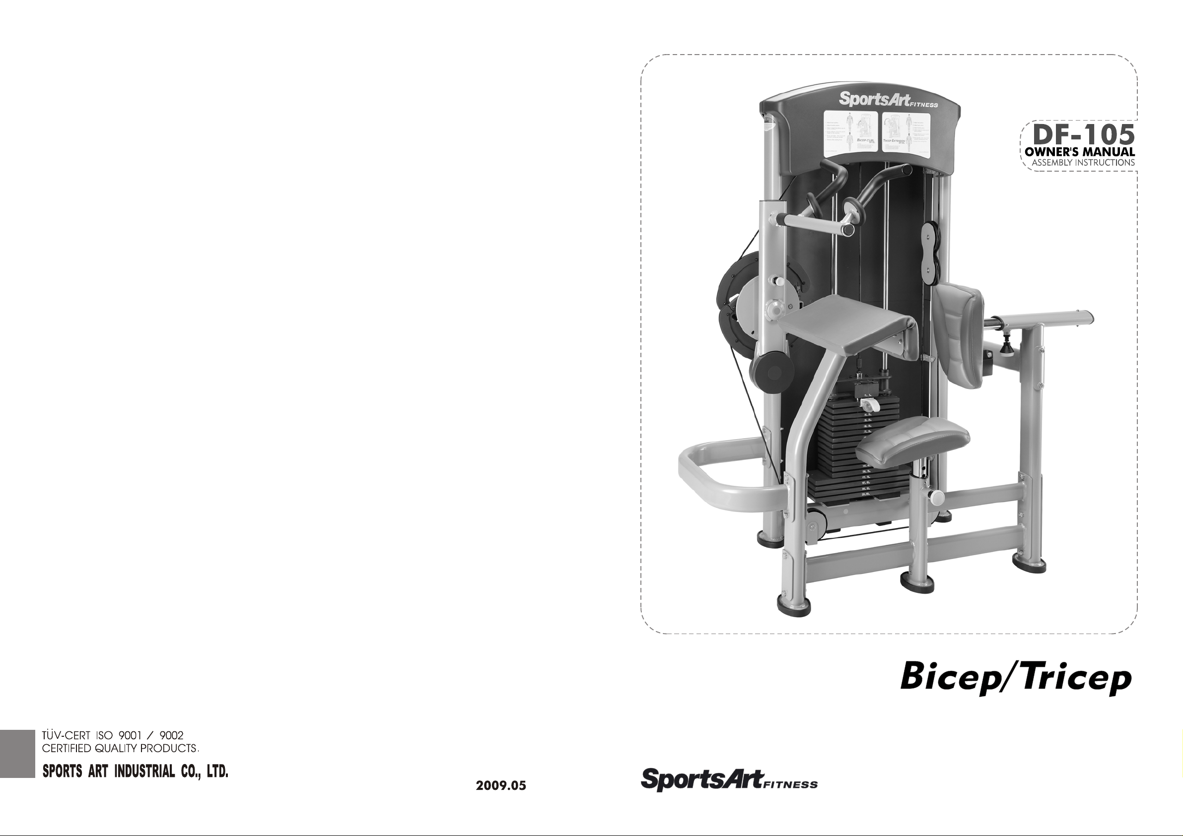
SportsArt Fitness DF-105 Owner's Manual

TABLEOFCONTENTS
Chapter1SafetyInstructions....................................................................................
1.1SafetyPrecautions................................................................................................
Chapter2Instructions..............................................................................................
2.1Dimensions..........................................................................................................
2.2PartListForBoxA...............................................................................................
2.3PartListForBoxB...............................................................................................
2.4PartListForBoxC...............................................................................................
2.5ComponentsintheHardwareKit..........................................................................
2.6ComponentsoftheProduct..................................................................................
Chapter3AssemblyInstructions...............................................................................
STEP1MainFrameAssembly..................................................................................
STEP2WeightPlateInstallation................................................................................
-
-
-
1
1
2
2
3
4
4
5
6
7
7
14
STEP3ApplytheWeightStackSticker.....................................................................
STEP4CableInstallation..........................................................................................
STEP5HandleInstallation........................................................................................
STEP6SeatBackandBottomInstallation...............................................................
STEP7CableAdjustment.........................................................................................
STEP8InstallTowerBackCovers............................................................................
STEP9InstalltheFrontTopCover...........................................................................
STEP10InstalltheRearTopCover..........................................................................
STEP11InstallWaterBottleHolder..........................................................................
STEP12StackFork..................................................................................................
Chapter4OperationInstructions............................................................................
4.1OperatingtheProduct.........................................................................................
4.2Test......................................................................................................................
-
22
24
30
31
32
33
35
36
37
38
39
39
41
4.3Maintenance.......................................................................................................
42

CHAPTER1SAFETYPRECAUTIONS-
1.1SAFETYPRECAUTIONS
Readandfollowallcautionarymessagesandwarningsinthismanual.Obtain
●
instructionsontheproperuserofthismachinepriortoexercising.Useappropriate
bodypositioningandcontrolledmovements.
Assemblyandoperatethisproductonasolid,levelsurface.Donotuseoutdoors
●
ornearwater.
Neverallowchildrenonorneartheequipment.
●
Makesureallfastenersareproperlytightenedforsafety.DONOTusetheproduct
●
iftheunitisdisassembledinanyway.
Keepyourhead,body,limbs,andfingersclearofallmovingparts.
●
Ifatanytimeduringexerciseyoufeelfaint,dizzy,orexperiencepain,stop
●
exercisingandconsultyourphysician.
DONOTwearlooseordanglingclothingwhileusingtheequipment.Keepaway
●
fromallmovingparts.
Usercarewhenmountinganddismountingtheunit.
●
DONOTuseanyaccessoriesthataren'tspecificallyrecommendedbythe
●
manufacture.Aftermarketaccessoriesmightcauseinjuriesorcausetheunittofall.
Closesupervisionisnecessarywhenthisproductisusedby,on,ornear
●
adolescents,invalidsanddisabledpersons.
Usethisproductonlyforitsintendeduseasdescribedinthismanual.
●
Neveroperatethisproductifithasbeendamagedinanyway.Ifitisnotworking
●
properlyorhasbeendroppedordamaged,contactyourdealer.DONOTattempt
tofixabrokenorjammedmachine.Contactaqualifiedfitnessproducttechnician.
Neverdroporinsertanyobjectintoanyopening.
●
-1-
CHAPTER2INSTRUCTIONS-
2.1DIMENSIONS
-2-
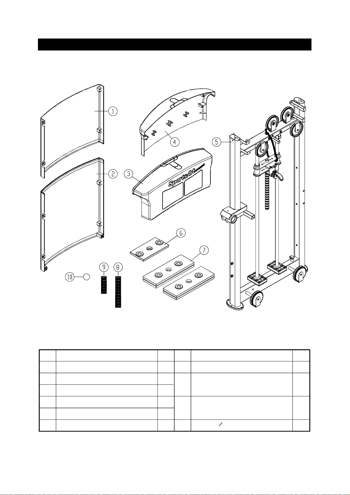
2.2PartListForBoxA
No. Description Qty
UpperRearCover
1
LowerRearCover
2
FrontTopCover
3
RearTopCover
4
MaiFrame
5
5KGWeightStack
6
1
1
1
1
1
1
-3-
No.
7
7.5KGWeightplate
Weightplatesticker
8
(10kg~60kg)
Weightplatesticker
9
(65kg~100kg)
StickerO25
10
QtyDescription
4
1
1
1
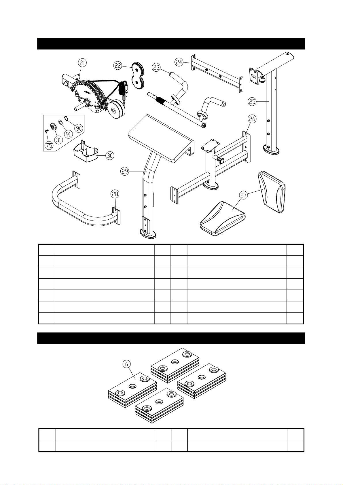
2.3PartListForBoxB
No.
21
22
23
24
25
26
CAM
FloatingPulley
Handles
Connector
SeatBackSupport
SeatFrame
Description
2.4PartListForBoxC
Qty
1
1
1
1
1
1
No.
27
28
29
30
31
Description
SeatBottom(Back)
UConnector
ArmCushion
BottleHolder
Axlecover(Large)
Qty
2
1
1
1
1
No.
6
Description
5KGWeightPlate
Qty
12
-4-
No.
Description
Qty

2.5ComponentsintheHardwareKit
Ahardwarekitisprovidedinthepackagingofthisproduct.Pleaseinspectthehardware
kitforthefollowingitems.
No. Description Qty
Softcapforcover
41
RearcoversetplateA
42
RearcoversetplateB
43
MushroomtopPhillipsheadscrew
44
Cableprotector
45
Rearcoverbracket
46
L-shapedAllenwrench
L-shapedAllenwrench
L-shapedAllenwrench
Openendwrench
Phillips-headscrewdriver
Ifyoudiscoveritemsmissingordamagedinshipping,pleasecontacttheSportsArt
ServiceDepartment.Keepthehardwarekitinasecureplaceforfutureuse.Toolsmay
beneededtodisassembletheproductinpreparationformovingorotheractivities.
5
4
4
24
12
1
2
1
1
2
1
Specification
Small
M5*L12
SGN-07
(M4)
(M5)
(M6)
(13*17)
ToolNeeded
-5-
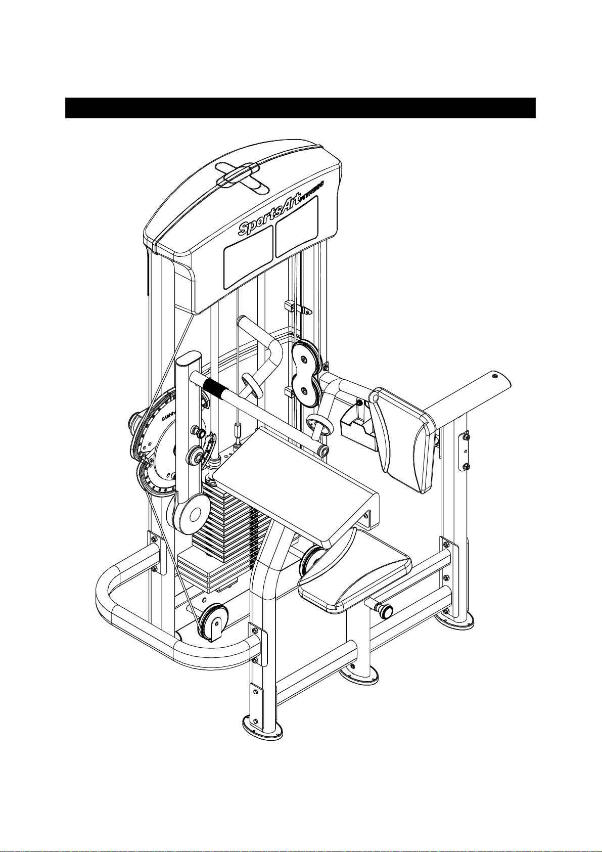
2.6ComponentsoftheProduct
Somecomponentsareinstalledontheproduct.Theseitemswillbeneededfor
productassembly.
No. Description
ConnectorSet
61
FlatWasher
62
ConnectorB
63
Washer
64
HexLocknut
65
HexBolt
66
SpringWasher
67
Connector50
68
UpperStackCarriage
69
HexBoltandPUTube
70
FlatWasher
71
HexLocknut
72
GuideRod
73
StackFork
74
∮
Qty
Specification
ψ
ψ
20*6.3
ψ
ψ
16*10.2
M10
M10*L130
M10
ψ
ψ
17*8.3
M8
ToolNeeded
InnerHexCapScrew
75
InnerHexcapScrew
76
Axle
77
SpringWasher
78
MushroomTopInnerHexScrew
79
PulleyA
80
PulleyB
81
CoverPlate
82
PulleyCover
83
SpringWasher
84
SeatBackPlate
85
MushroomTopInnerHexScrew
86
BeveledInnerHexScrew
87
PlasticInnerHexScrew
88
WaveWasher
90
Washer
91
M8*L20
M6*L30
M6
M6*L12
M8
M8*L25
M8*L20
M6
ψ
ψ
38*30
ψψ
40*30.5*t3
-6-
CHAPTER3ASSEMBLYINSTRUCTIONS-
STEP1
MainFrameandCAMAssembly
-7-
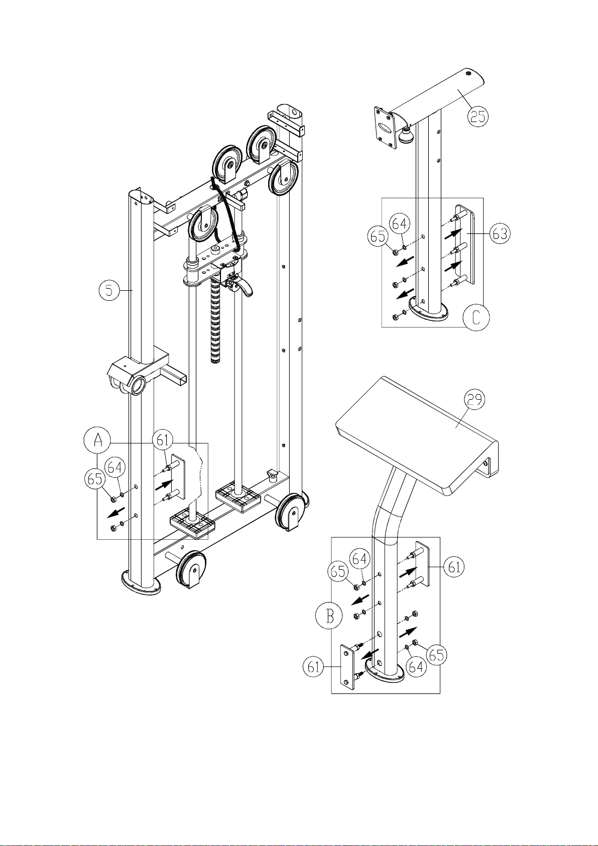
1-1.Loosenandremovenuts(64,65)fromconnectors(61,63)inareasA,B,Cas
shown.Carefullyseteachpieceaside.
-8-
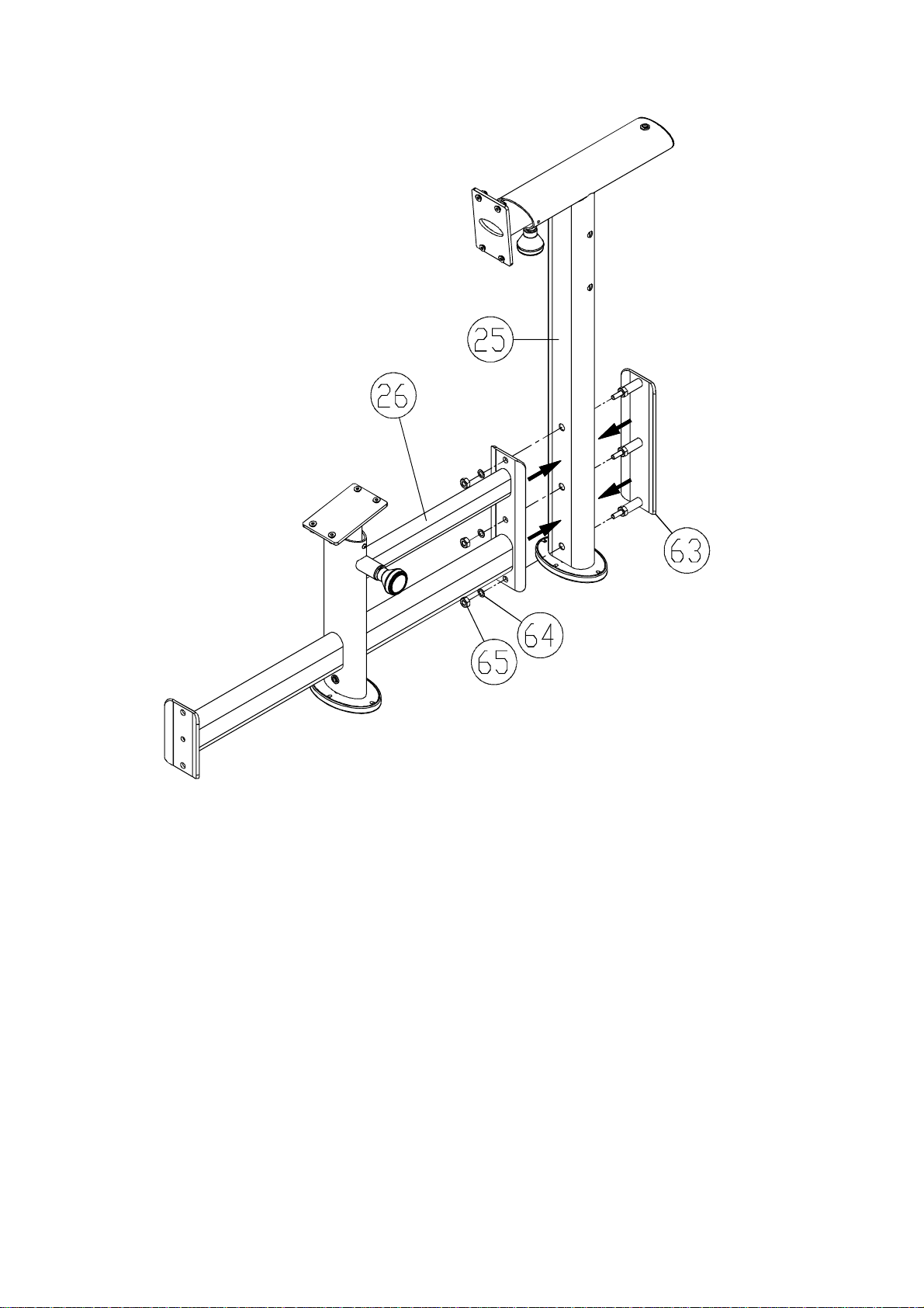
1-2.Useconnectors(63)toconnectseatsupport(26),andbacksupport(25).Secure
themwithnuts(64,65)asshown.
-9-
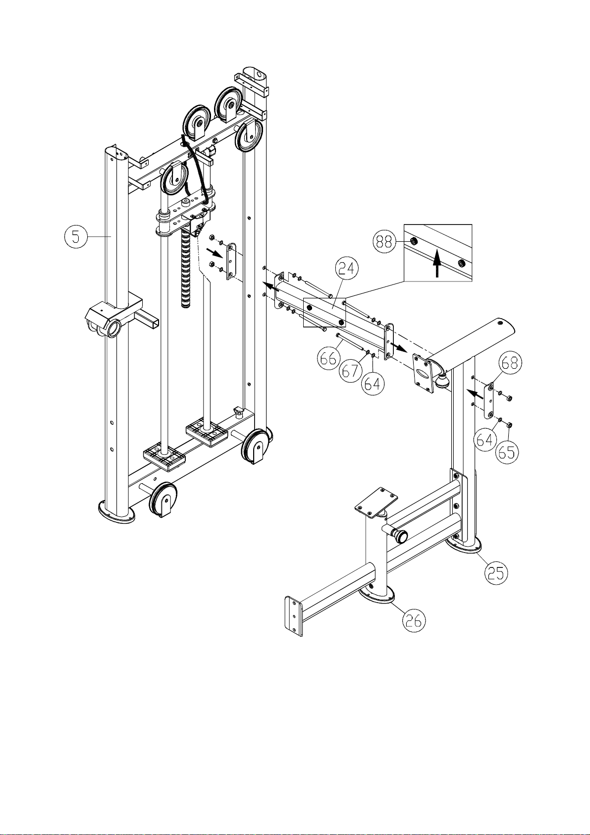
1-3.Useconnector(24)toconnectthemainframe(5)andsupports(25,26).Secure
theconnector(68)withhardware(64,65,66,67).
Placetheplasticscrews(88)faceupontheconnector(24).NOTE:
-10-
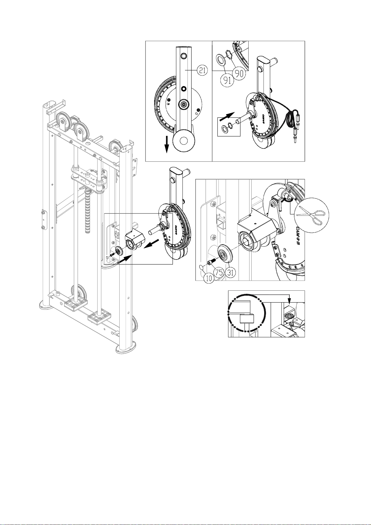
1-4.CAMAssembly
(a)Rotatethecam(21)asshown.Theninsertthewaveandflatwashers(90,91)onto
theaxle.
(b)Afterinstallingthewashers,slidethecam(21)intoplaceonitsmountarea.
(c)Finally,securetheaxlecover(31,75)intoplace.Thenapplythesticker(10)as
shown.
(d)Cutofftheziptie.Uncurlthecable.
Thestoppermustrestbelowthetubeasshown.NOTE:
-11-
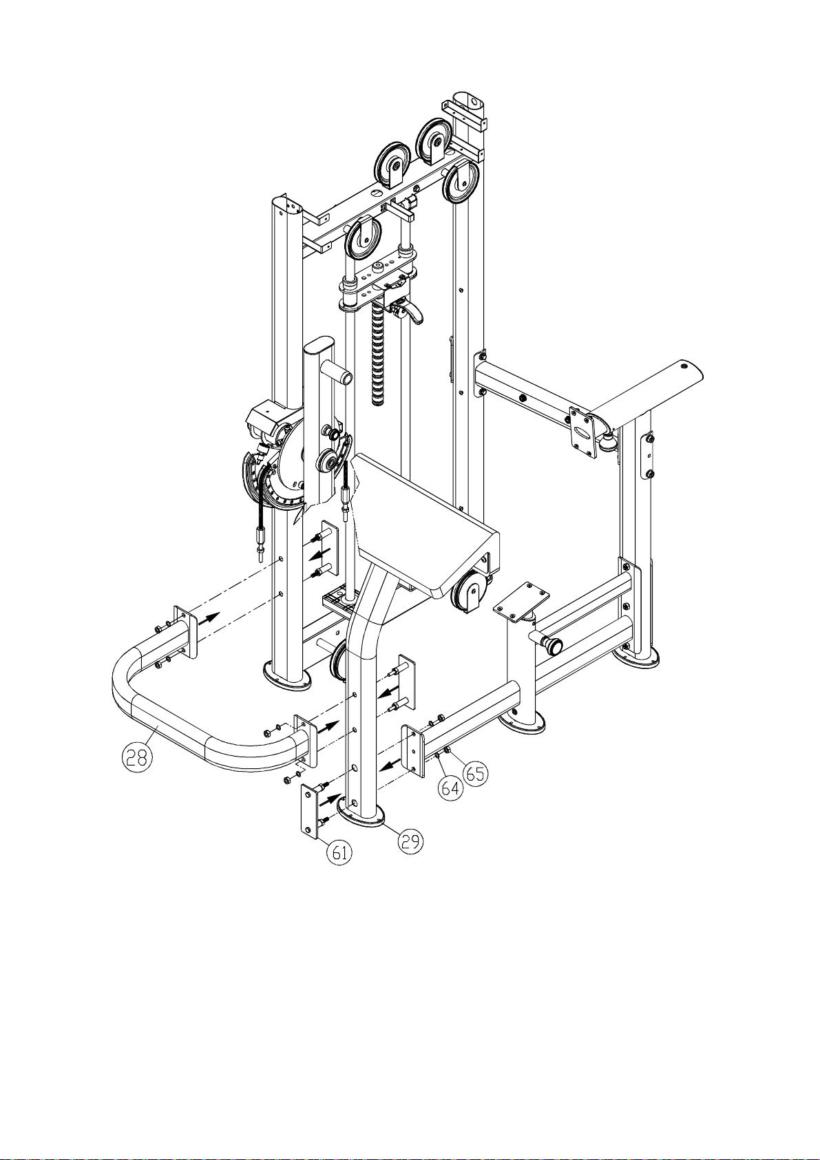
1-5.AfterCAMassembly,useconnectorset(61)toconnectUconnector(28)andarm
cushion(29)withscrews(64,65)loosely.
1-6.Puttheunitflatonthefloor.SecuretheUconnector(28).Thensecureotherscrews.
-12-
 Loading...