

SportsArt Fitness C520U, C531U Repair Manual

C520U/C531U Repair Manual

Table of Contents
1-1-1. Display Picture – C520/C531
1-2-1. Component Placement - C520U/C531U Display
1-2-2. Component Placement - C520U/C531U Lower Body
1-3-1. Block Diagram - C520U/C531U Electronics
1-4-1. Wire Connections - C520U/C531U Display
1-4-2. Wire Connections - C520U/C531U Drive Board
1-5-1. LED Indicators - C520U / C531U Display Board
1-5-2. LED Indicators - C520U/C531U Drive Board
1-6-1. C520U/C531U Display Specifications
2-1-1. Display Malfunction Troubleshooting Table - C520U/C531U
2-1-2. Display Malfunction Troubleshooting Table - C520U/C531U, Continued.
3-1-1. Malfunction: Unit will not start (alternator).
3-2-1. Malfunction: Unit will not start (battery).
3-3-1. Malfunction: No RPM value
3-4-1. Malfunction: No resistance
3-5-1. Malfunction: Resistance is heavy.
3-6-1. Malfunction: Telemetry heart rate malfunction.
3-7-1. Malfunction: HTR heart rate malfunction
4-1-1. Mechanical Maintenance Schedule - C531U/C520U
4-2-1. Mechanical Troubleshooting Chart - C520U/C531U.

1-1. Display Picture - C520U/C531U
1-1-1
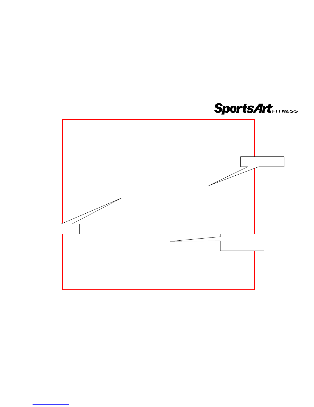
1-2. Component Placement - C520U/C531U Display
1-2-1
HR telemetry
receiver board
HTR board
Display board
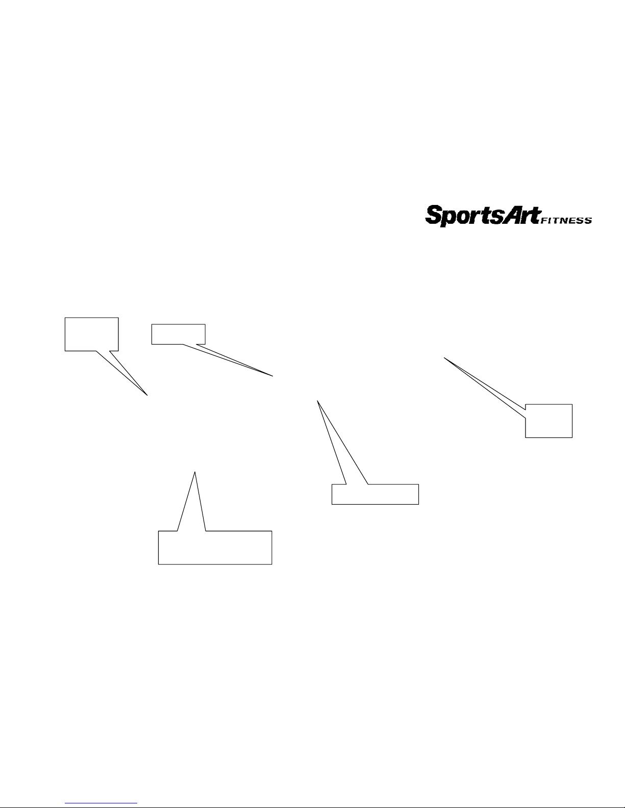
1-2. Component Placement - C520U/C531U Lower Body
1-2-2
Electromagnet
Drive
board
Flywheel with built-in
alternator
Battery
Reed switch
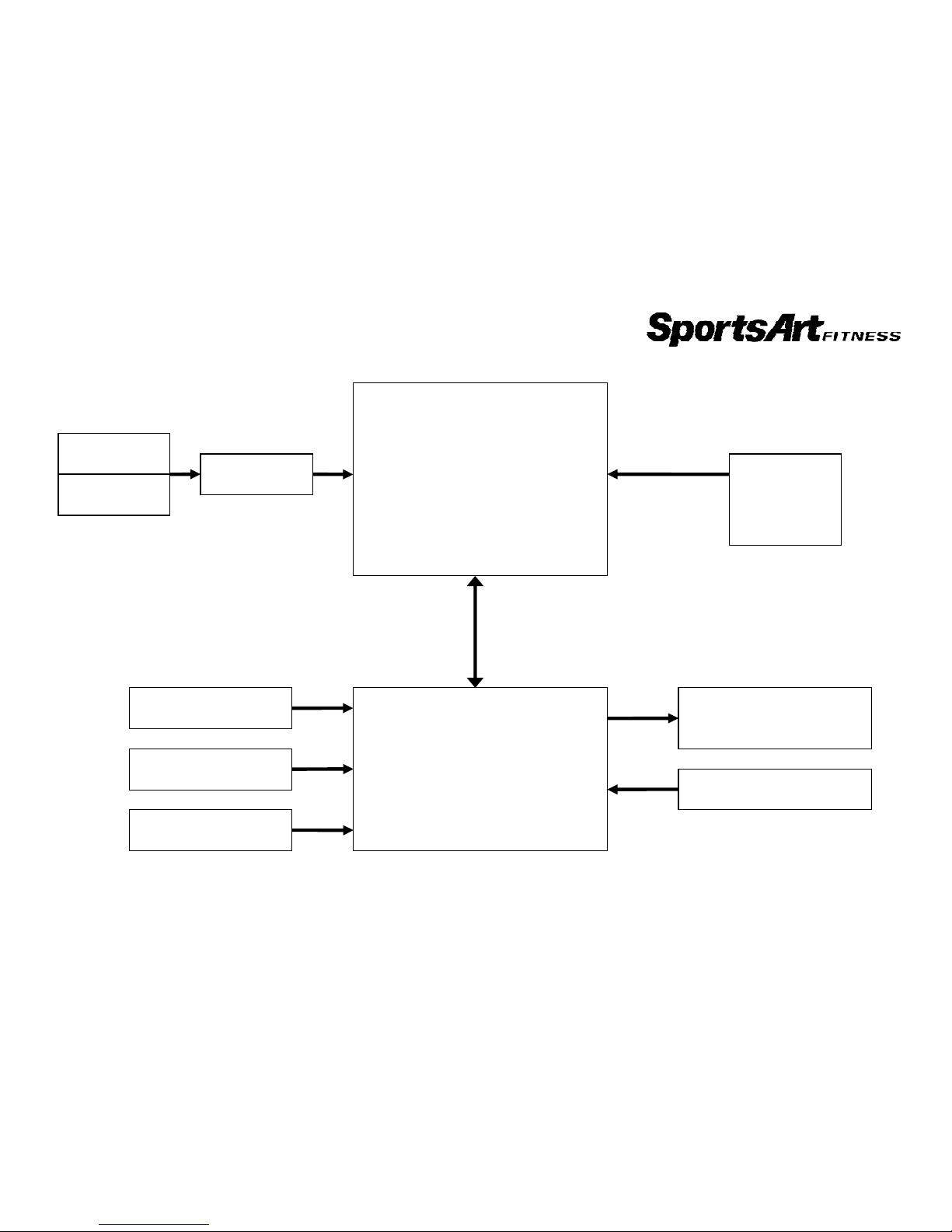
1-3. Block Diagram - C520U/C531U Electronics
1-3-1
Display
Board
Drive
Board
Electro-magnet
Reed switch
Battery
HTR board HR receiver
board
Sensor – L
Sensor – R
Alternator
Battery charger
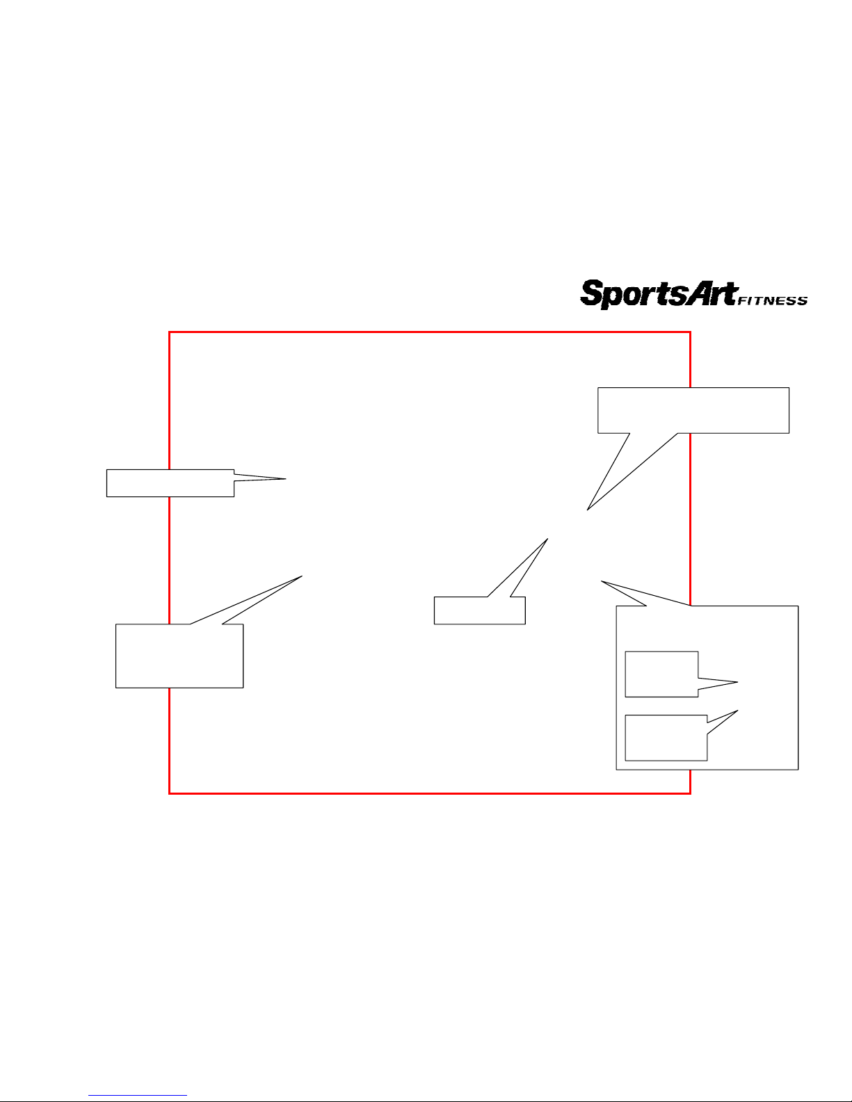
1-4. Wire Connections - C520U/C531U Display
1-4-1
To HTR contact plates (left
and right)
LED1
Display power
supply
To drive board
To HTR
board
To HR
receiver
To display
 Loading...