

SportsArt Fitness A989 Owner's Manual
Sports Art Industrial Co., Ltd. TUV-CERT ISO 9001/9002/14000 Certifi ed Quality Products 2013.01
A989 Hack Squat
Owner’s Manual

A989 OWNER’S MANUAL CONTENTS
1. INTRODUCTION ................................................................................ 2
2. SAFETY PRECAUTIONS .................................................................. 3
3. LIST OF PARTS ................................................................................. 4
4. ASSEMBLE THE PRODUCT ............................................................. 6
STEP 1 Assemble the Main Components .............................................. 6
STEP 2 Install the Cushions and Handles ............................................ 9
STEP 3 Install the Weight Plate Pegs .................................................. 11
STEP 4 Level the Unit ........................................................................... 12
5. OPERATE THE PRODUCT ............................................................... 13
OPERATION Placement Settings .......................................................... 13
OPERATION Operate the Product ........................................................ 14
6. MAINTENANCE ................................................................................ 15
MAINTENANCE Glide Rail Cleaning ................................................... 15
MAINTENANCE Schedule .................................................................... 16
MAINTENANCE Task List .................................................................... 17
MAINTENANCE One-Year Maintenance Log ....................................... 18
7. CONSIGNES DE SÉCURITÉ IMPORTANTES ................................. 19
2
1. INTRODUCTION
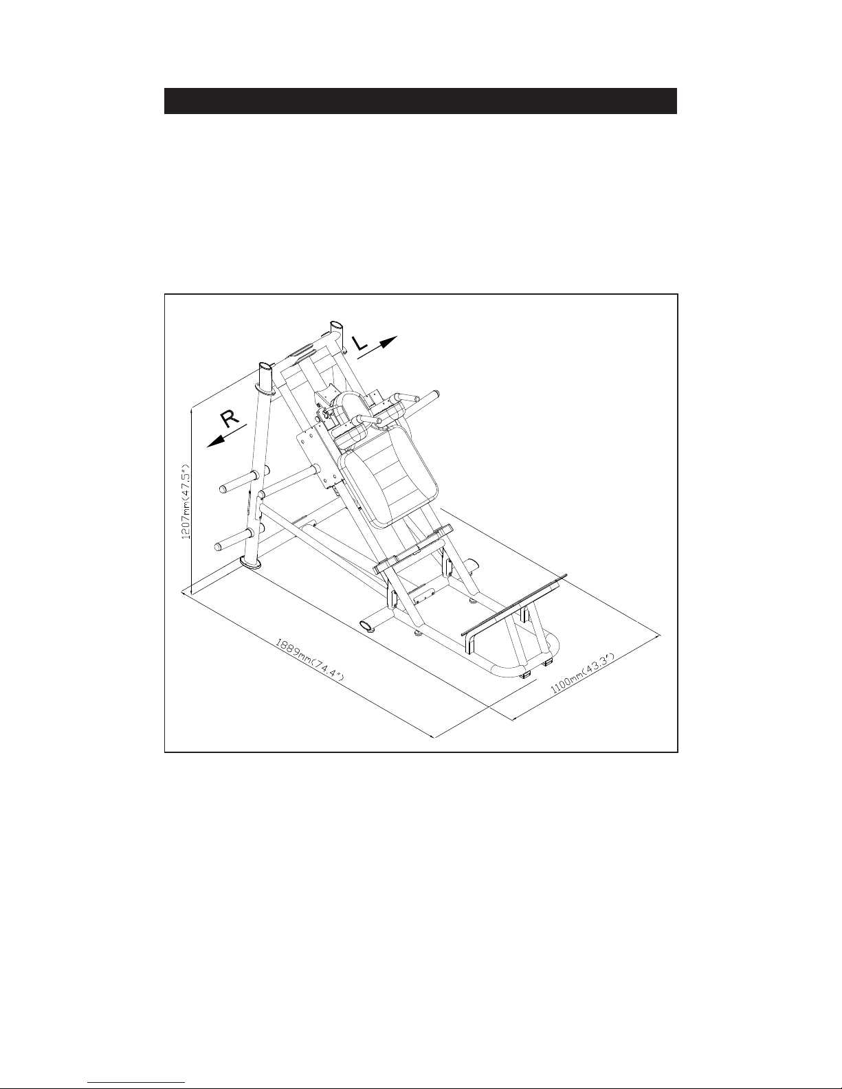
Congratulations on the purchase of a high quality SportsArt product, the A989 hack
squat machine. Constructed of high quality materials and designed for years of
reliable performance, this product was made for full commercial use.
Before this product is assembled or operated, we recommend that you familiarize
yourself with this manual. Understanding the correct assembly and operation of
this product will help ensure that exercisers obtain their tness goals safely and
successfully.

3
2. SAFETY PRECAUTIONS
This product was designed and built for optimum safety. However certain precautions apply during the use of this product. Please note the following safety
precautions:
• Please read the entire manual before assembly and operation. Make
sure the product is installed and operated as instructed in this manual.
• Assemble and operate the product on a solid, level surface. Do not use
outdoors or near water, including pools and saunas.
• Check the product before every use. Make sure all parts are assembled, and all fasteners are tightened. Do not use the product if it is disassembled in any way.
• Wear proper workout clothing. Do not wear loose clothing. Do not wear
shoes with leather soles or high heels. Tie all long hair back. Do not go
barefoot on this product.
• Keep away from moving parts. Moving parts may or may not stop immediately if an object becomes caught or impedes normal motion.
• Use this product only for its intended purpose as described in this
manual.
• Be careful when mounting and dismounting the unit.
• Never operate this product if it has been damaged in any way. If it is
not working properly, or has been dropped or damaged, contact a service
technician for repairs.
• Do not use accessories that are not specically recommended by the
manufacturer. Such parts might cause injuries or cause the unit to fail.
• This product is not intended for use by persons (including children) with
reduced physical, sensory, or mental capabilities, or by people who are
otherwise decient in product knowlege or experience. If such people use
this product, they should be given training and be supervised at all times
by someone responsible for their safety.
• Children should be supervised to ensure that they do not play on or
near the product.
• The user weight limit for this product is 227 kg, 500 lb.
CAUTION: If you feel any pain or any abnormal sensations, STOP YOUR
WORKOUT and consult your physician immediately. Work within your recommended exercise level. DO NOT work to exhaustion. Before beginning any
exercise program, you should consult with your doctor. It is recommended that you
undergo a complete physical examination.
4
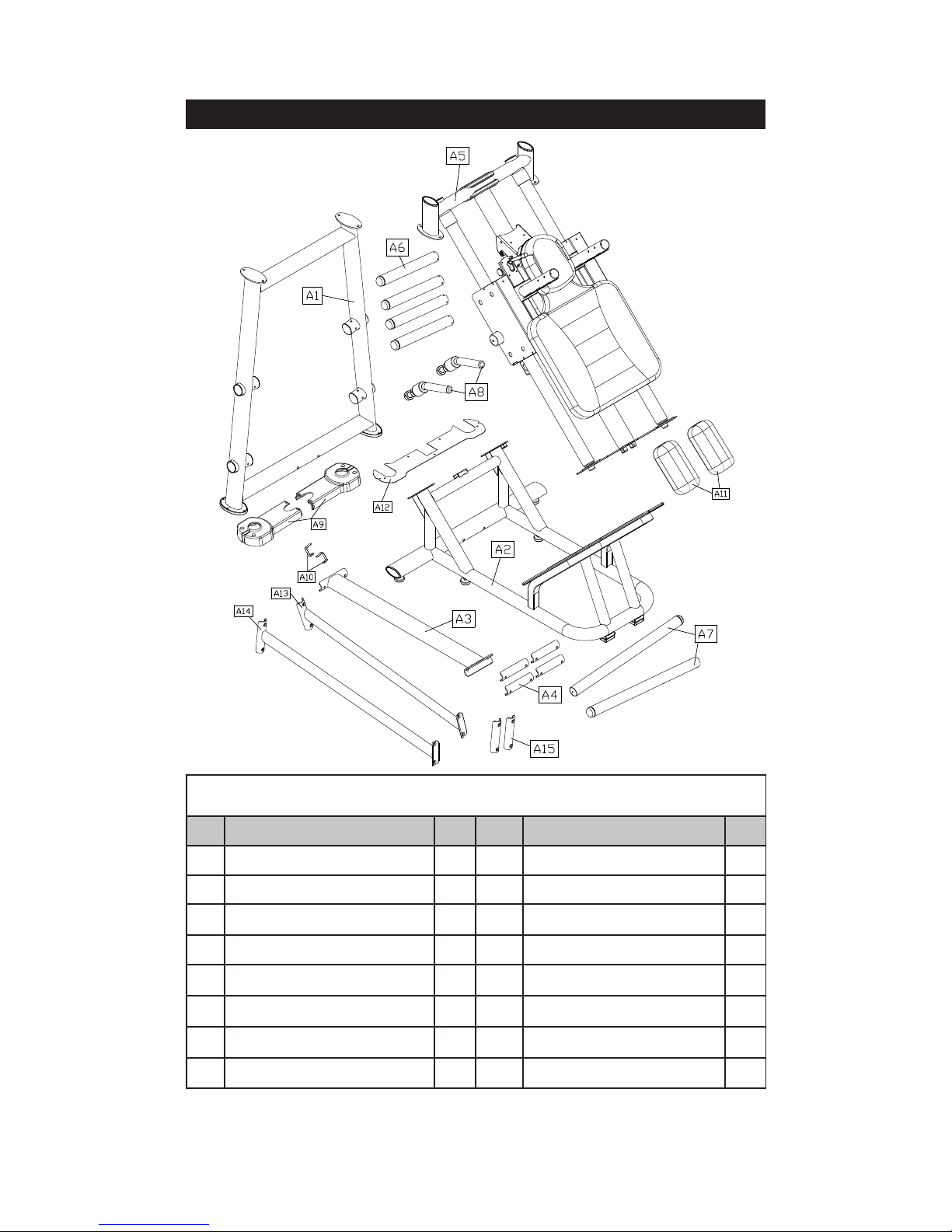
3. LIST OF PARTS
Assembly Parts
No. Name Qty. No. Name Qty.
A1 Upright frame 1 A9 Cover 2
A2 Base 1 A10 Security clip 2
A3 Link tube 1 A11 Cover set plate 2
A4
Connector plate
4 A12
Clip
1
A5 Inclined frame 1 A13 Lower left bracket tube 1
A6 Weight plate peg 4 A14 Lower right bracket tube 1
A7 Weight plate peg (long) 2 A15 Connector plate 2
A8 Handle 2
5
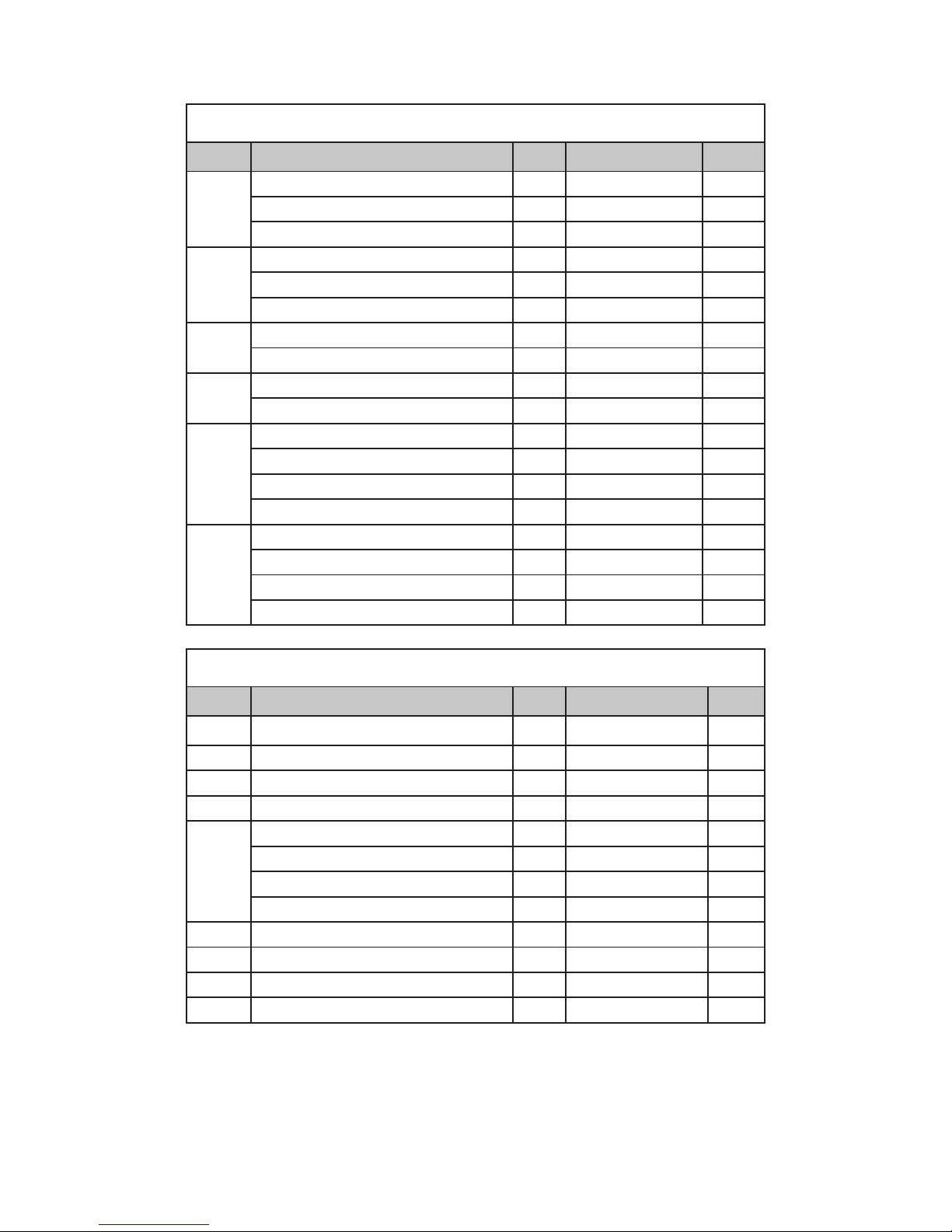
Components on the Product
No. Name Qty. Specication Notes
31
Mushroom top inner hex screw 8 M8*P1.25*L20
Spring washer 8 M8
Flat washer 8 D22*d8.2*t2
32
Mushoom top inner hex screw 8 M8*P1.25*L20
Spring washer 8 M8
Handle washer 8 D18*d8.5*t2
33
Mushroom top inner hex screw 16 M6*P1.00*L15
Handle washer 16 D20*d7*t2.0
34
Inner hex screw 13 M5*P0.8*L15
Flat washer 13 D16*d6.3*t2
35
Hex screw 6 M10*P1.5*L30
Spring washer 6 M10
Flat washer 12 D21*d10.5*t2
Hex lock nut 6 M10
36
Hex nut 4 M10*P1.5*L30
Spring washer 4 M10
Flat washer 8 D21*d10.5*t2
Hex lock washer 4 M10
Components in the Hardware Kit
No. Name Qty. Specication Notes
41 Hex screw 8 M10*P1.5*L130
Spring washer 8 M10
Washer 16 D16*d10.2*t1.0
Hex lock washer 8 M10
42
Hex screw 4 M10*P1.5*L75
Spring washer 4 M10*t1.0
Flat washer 8 M16*d10.2*t1
Hex lock washer 4 M10
L-shaped Allen wrench 1 M6
L-shaped Allen wrench 1 M4
Double open-end wrench 2 13*17
Silicone lubricant (maintenance) 1 50 cc
6
4. ASSEMBLE THE PRODUCT
Follow instructions below to assemble this product. Note that in this manual
the words “left” and “right” are used to refer to the product and its parts. As
such, these designations correspond to the “left” and “right” sides of a person
in position to exercise on this product. Also, for brevity, the word “screws” is
used where screws, washers, and other hardware may be involved.
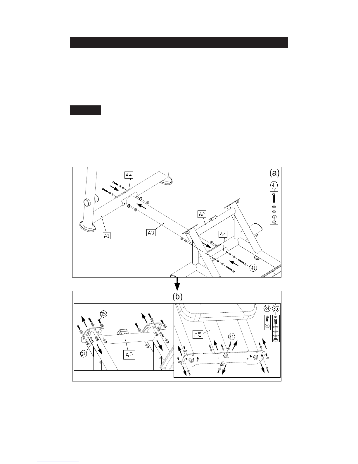
STEP 1 Assemble the Main Components
Please follow instructions (a) through (d) to assemble the main components.
(a) Use screws (41) to secure the link tube (A3) and connector plate (A4) onto
the upright frame (A1) and base (A2).
(b) Hold the inclined frame (A5) onto the base (A2), and loosely secure
screws (34,35).
 Loading...