

SportsArt Fitness 8300, E8300 Mechanical Repair Manual
8300 and E8300 Elliptical Trainer – Mechanical Repair Guide
Version 2.1. Revised 03-18-05

E8300 and 8300 Elliptical Trainer Mechanical Repair Manual
This troubleshooting manual was made through the cooperation of SportsArt personnel in the USA and Taiwan.
Our goal is to provide clear, useful troubleshooting information for technicians in the field. If you have questions, comments or suggestions,
please contact Bob Baumgartner at SportsArt America. Thank you.
E-mail: bob@sportsartamerica.com
Tel: 866 709 1750 ext. 115
E8300 and 8300 Elliptical Trainer Mechanical Repair Manual
Version 1: December 31, 2003
Version 2: September 28, 2004 - Minor organizational changes were made
Version 2.1: March 18, 2005 – Part list removed due. Please see product blowups and part lists on our web site.
Notes:
(1) Some parts of this manual refer to the 8300 Elliptical Trainer and no reference to the E8300 is made.
Mechanically, the 8300 and E8300 are the same. No effort was made to include the word E8300 on every page.
(2) Part numbers listed in this manual are factory part numbers – not part numbers used by SportsArt America –
and are subject to change. Please see the website, www.sportsartamerica.com, for updates.
8300 and E8300 Elliptical Trainer – Mechanical Repair Guide - Contents
Chapter 1 – Blowup Diagram and Part List
1-1-1Blowup Diagram and Part List – CONTENTS REMOVED 03-18-05; SEE BLOWUP DIAGRAM.
Chapter 2 - Component Removal and Installation Procedures
2-1-1 Access Cover Removal and Installation
2-2-1 Stride Motor Removal and Installation
2-3-1 Flywheel Removal and Installation
2-4-1 Flywheel Washer Removal and Installation
Chapter 3 - Troubleshooting
3-1-1 Pulsating Vibration
Chapter 4 – Design Change Record
4-1-1 Changes Due to Rust Issue
4-2-1 Change to Prevent Foam from Sliding Down
Version 2.1, Revised 03-18-05

8300 and E8300 Elliptical Trainer – Mechanical Repair Guide
Chapter 1 – Blowup Diagram and Part List
1-1-1 Blowup Diagram and Part List
CONTENTS REMOVED 03-18-05;
PLEASE REFER TO BLOWUP DIAGRAMS AVAILABLE ON THE WEB SITE.
Version 2.1
Revised 03-18-05
8300 Elliptical Trainer – Mechanical Repair Guide
Chapter 2 - Component Removal and Installation Procedures
2-1-1 Access Cover Removal and Installation
2-2-1 Stride Motor Removal and Installation
2-3-1 Flywheel Removal and Installation
2-4-1 Flywheel Washer Removal and Installation
Version 2
Revised 09-28-04
SportsArt America
8300 Component Removal and Installation Procedures
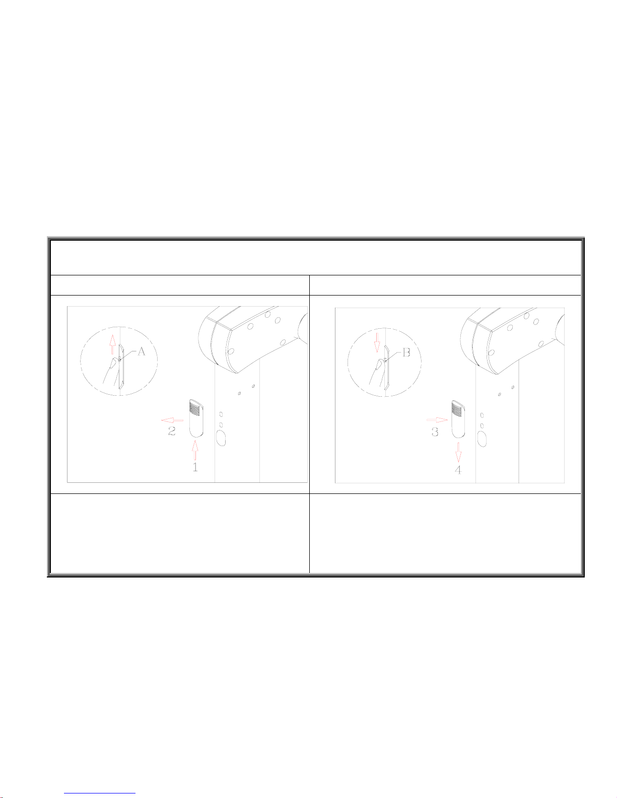
Access Cover Removal and Installation
Step 1 - Removal Step 2 - Installation
2-1-1
Step 4 Step 1
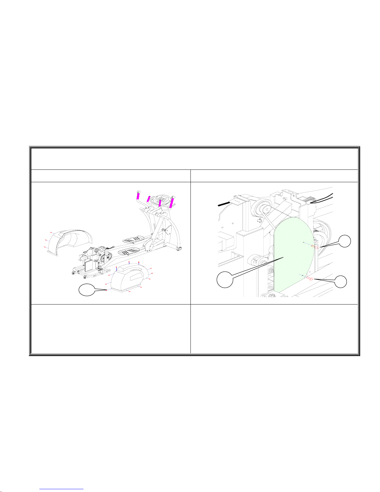
Remove the access cover by pressing up (1), then
pulling out (2) as shown above.
Reinstall the access cover by pressing in (3), then
pushing down (4).
SportsArt America
8300 Component Removal and Installation Procedures
Stride Motor Removal and Installation
Step 1 Step 2
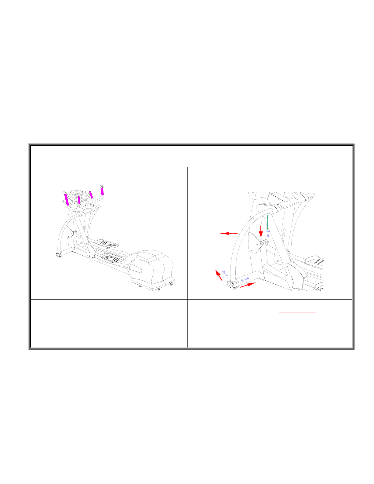
Use these instructions when calibrating or replacing the
stride motor sets.
Press the stride key on the display or the stride switch until
the display stride window shows 650mm (26in).
Continue to
exercise on the unit. After the stride linkage reaches its
destination, remove the stabilizing arms by removing the
mushroom-head hex screws.
2-2-1
SportsArt America
8300 Component Removal and Installation Procedures
Stride Motor Removal and Installation
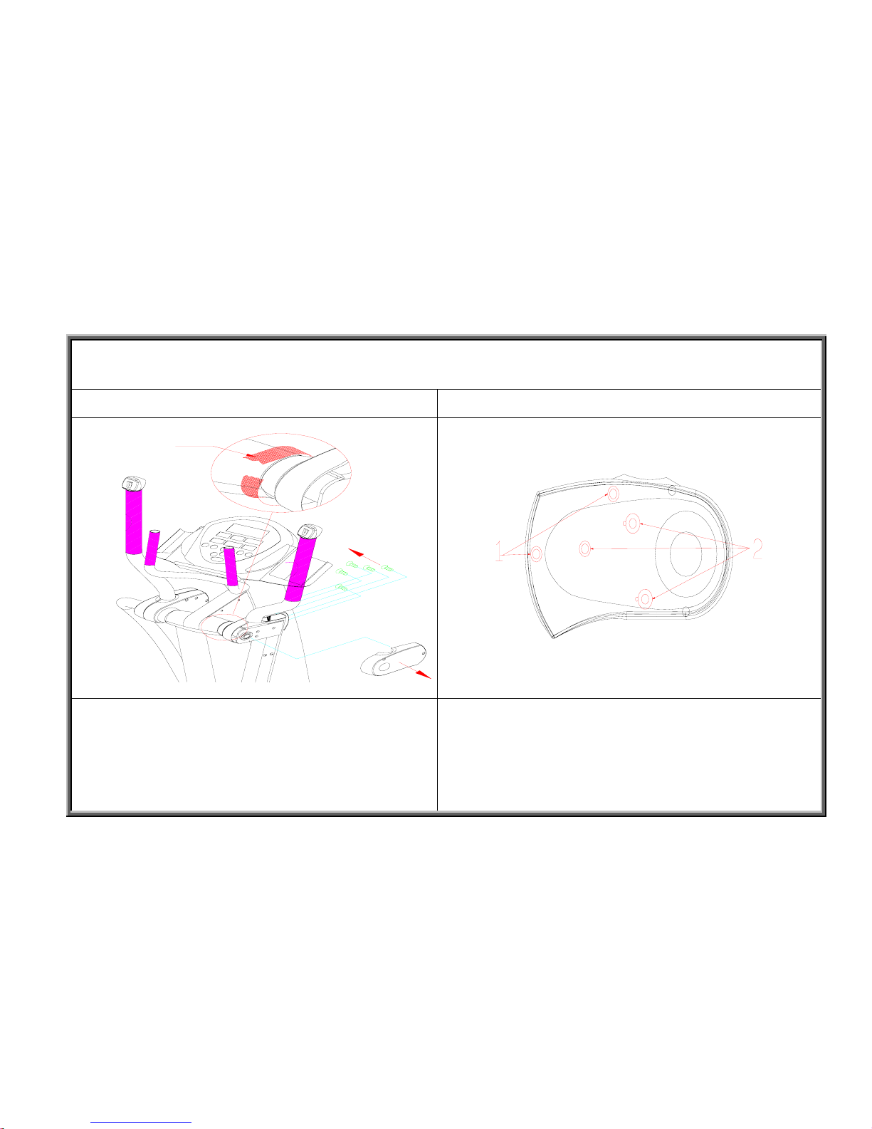
Step 3 Screw Types in the Shoulder Cover
Use tape to secure the inner cover (A). Remove the six
screws that secure the outer cover (B).
Remove the screws in this order: (1) Remove the
mushroom-top Phillips-head pointed screws; (2) Remove the
mushroom-top Phillips-head metal screws.
2-2-2
Tape
SportsArt America
8300 Component Removal and Installation Procedures
Stride Motor Removal and Installation
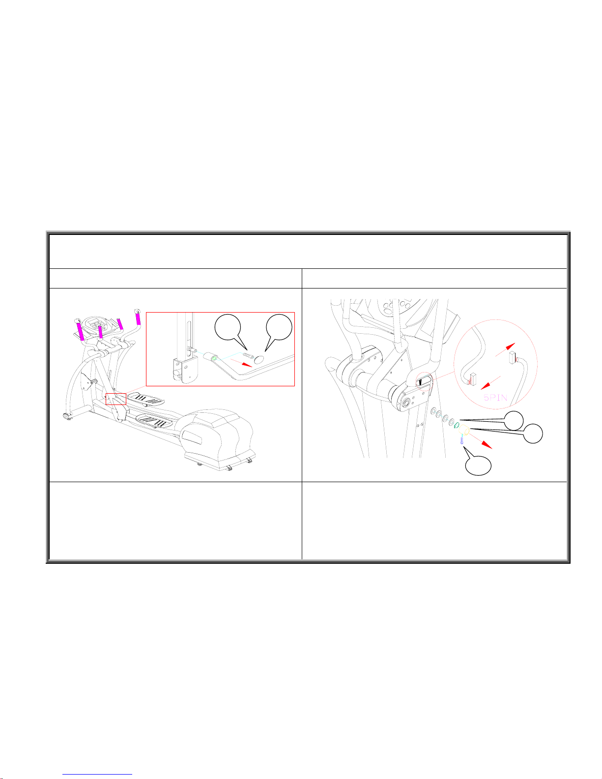
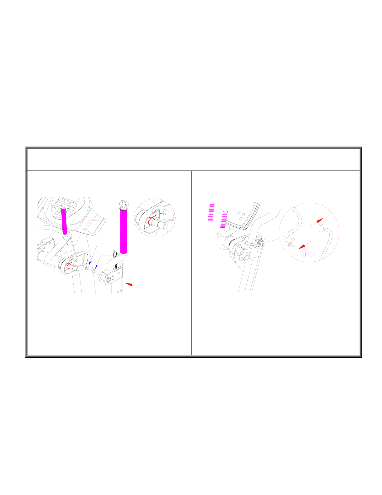
Step 4 Step 5
Remove the stride linkage bushing cover (B). Remove the
inner hex head bolt (A). Detach the stride linkage.
First, loosen the mushroom-head Phillips screw (C) that holds
the sleeve (A) in place. Remove the sleeve (A). Remove the
C-clip (B). Pull the stride support assembly out slightly. (Do
not pull it off the axle.) Disconnect the VR, motor, and switch
wires. Set them out of the way, and pull the stride motor up
and out of the stride support arm.
2-2-3
A B
SportsArt America
8300 Component Removal and Installation Procedures
Stride Motor Removal and Installation
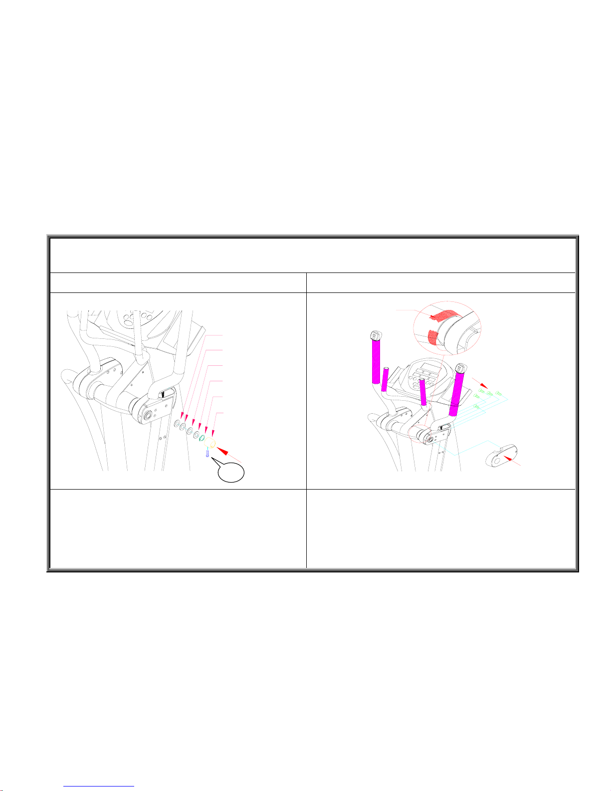
Step 6 Step 7
Remove the mushroom-head Phillips screws shown above
(A). Pull the stride motor set upward to remove it.
Note: In removing the stride motor set, push up on the
stride motor connection pin. Do not pull on the wires on
top.
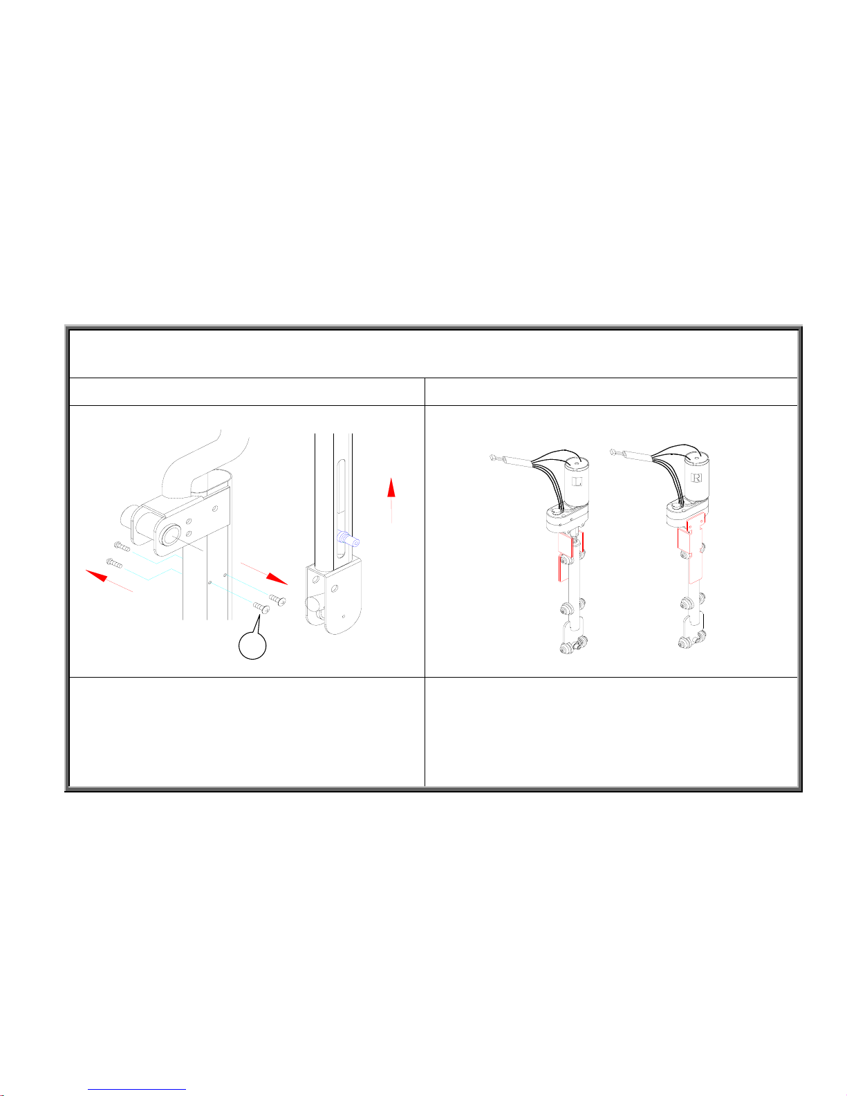
First, remove the protective bracket on the stride motor set.
Apply bearing grease to the worm gear and rollers. Then
insert the stride set into the stride support arm.
Note: Do not change the relationship of the brass stem to the
motor; ERR7 may result. Also, do not change the worm gear
position; The stride height may become uneven or jam.
2-2-4

SportsArt America
8300 Component Removal and Installation Procedures
Stride Motor Removal and Installation
Step 8 Step 9
In installing the stride motor set, note that the stride linkage
connector must face the stride linkage.
Note on alignment: The zirc fitting faces forward and the
stride linkage connector faces inside.
Use the stride linkage connector to guide the stride motor
set into place in the stride support arm. Then attach the
mushroom-head Phillips screws as shown. (Hex head screws
were later used in this spot.)
Note: In adjusting the stride motor set position in the support
arm, do not pull the wires; the VR circuit board might break.
2-2-5
馬達
軸心
油嘴
Motor
Connector
Zirc fitting
SportsArt America
8300 Component Removal and Installation Procedures
Stride Motor Removal and Installation
Step 10 Step 11
Before installing the stride support assembly, put the washers
in place on the pedestal shaft, with the regular washer on the
inside and the Teflon washer facing the stride support
assembly.
Note: Make the Teflon side face the stride support assembly.
Note: If the tape on the shoulder cover becomes detached, wrap the
wires around the shaft once, pushing them forward, then under and up.
Connect the VR, motor, and switch wires, then stuff the
connectors into the stride support arm.
2-2-6
A
B
SportsArt America
8300 Component Removal and Installation Procedures
Stride Motor Removal and Installation
Step 12 Step 13
Put the stride support assembly in place. Put on washers as
follows: Teflon washer (A), Teflon side facing the stride
support assembly, black washer (B), wave washer (C), black
washer (B), and C-clip (D). Finally, put the sleeve (E) in
place, then tighten the screw (F).
Put the outer cover in place. Screw in the five screws. An
d
remove the tape.
2-2-7
A
B
C
B
D
E
Tape
SportsArt America
8300 Component Removal and Installation Procedures
Stride Motor Removal and Installation
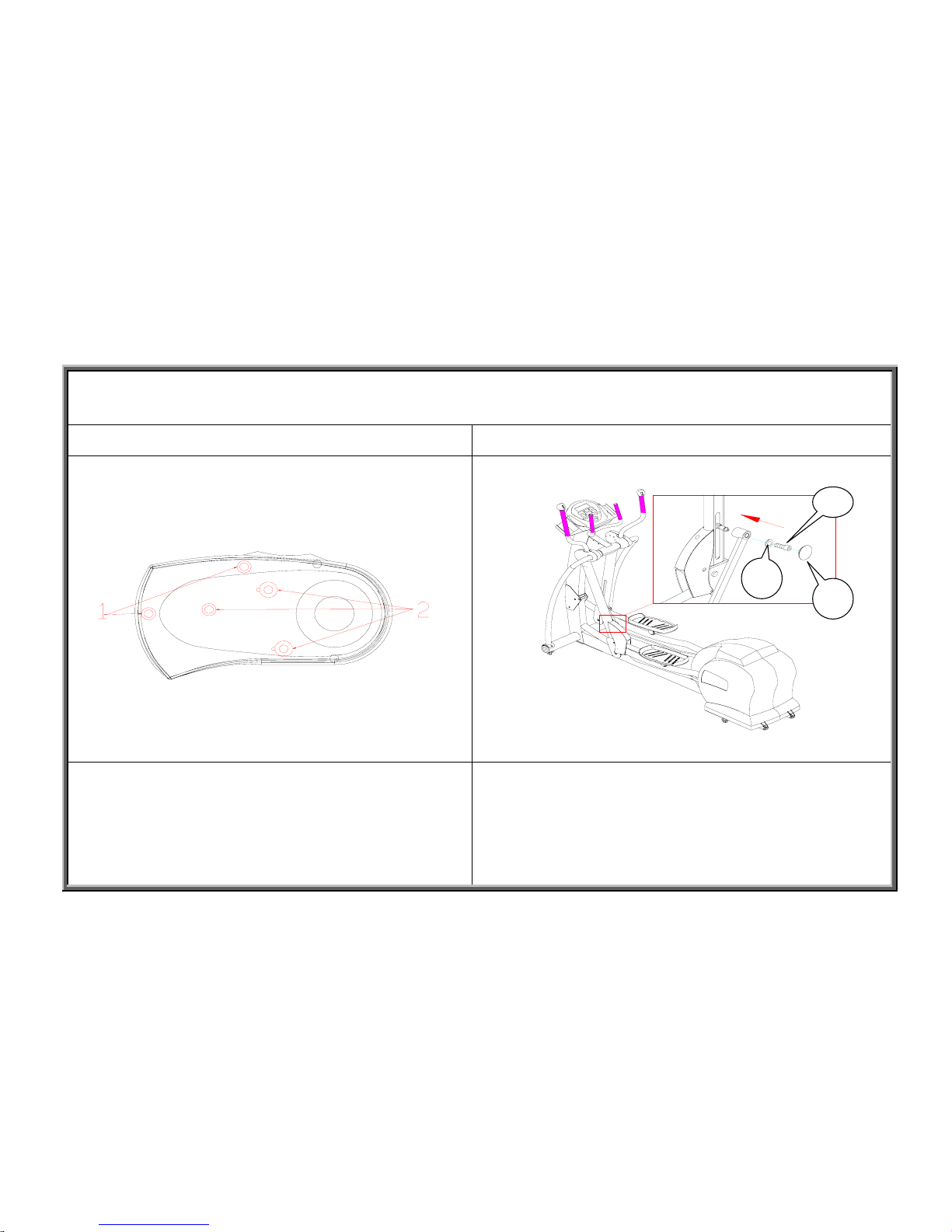
Outer Cover Screws Step 14
First screw in the metal screws (2), then the sharp screws (1). Install the stride linkage as shown. Put the flat washer (B) on
the stride linkage screw (A), and tighten down the screw.
Then put cover (C) in place.
2-2-8
C
B
SportsArt America
8300 Component Removal and Installation Procedures
8300 Stride Motor Removal and Installation
Step 15
Put support arms in place. Then tighten support arm screws
to complete the job.
A. Mushroom-head hex screws (5/16”*L19)
B. Support washer (D18*d8.5*t2); support washer
(D20*d7*t2.0)
C. Mushroom-head inner hex screw (1/4”*L3/4”)
2-2-9
A
B
C
D
SportsArt America
8300 Component Removal and Installation Procedures
Flywheel Removal and Installation
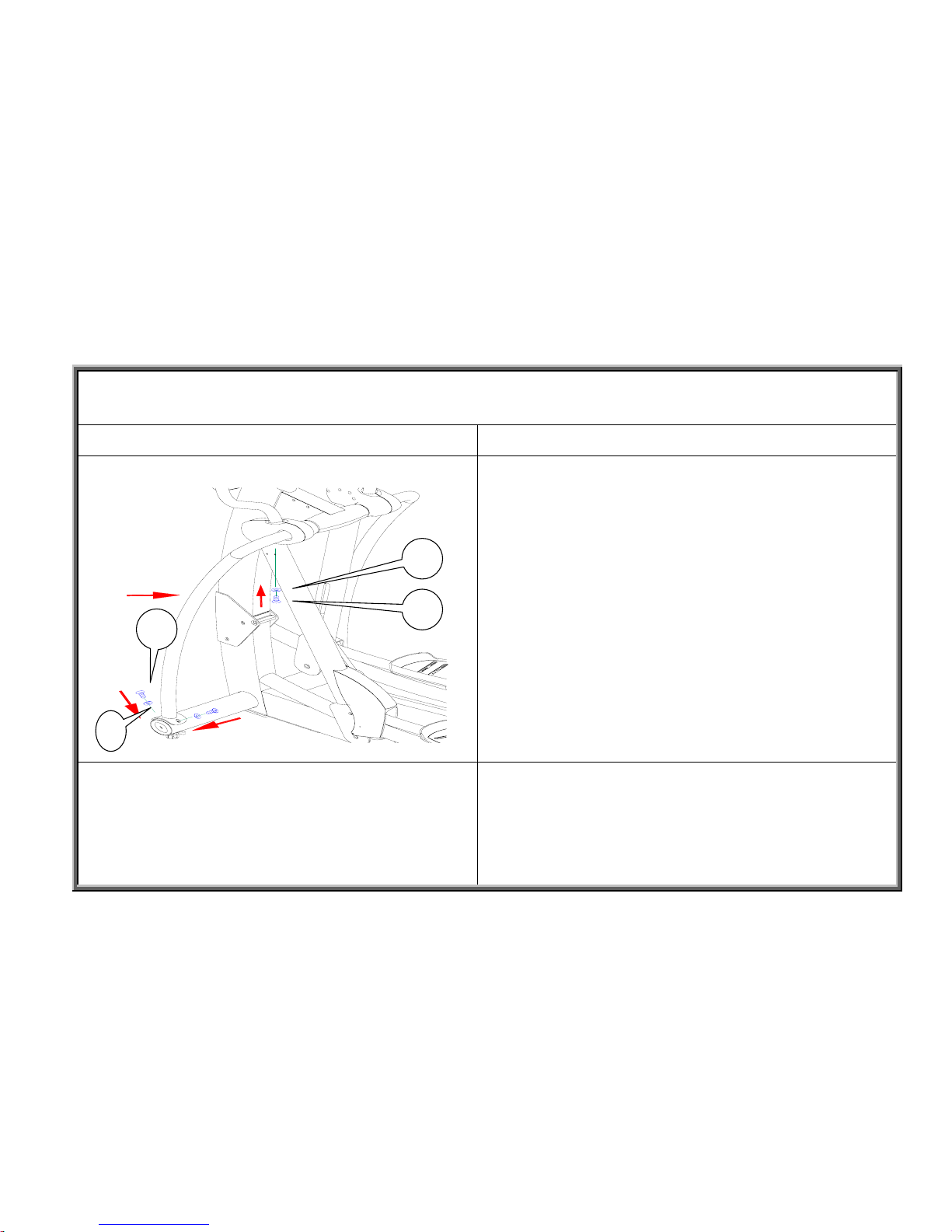
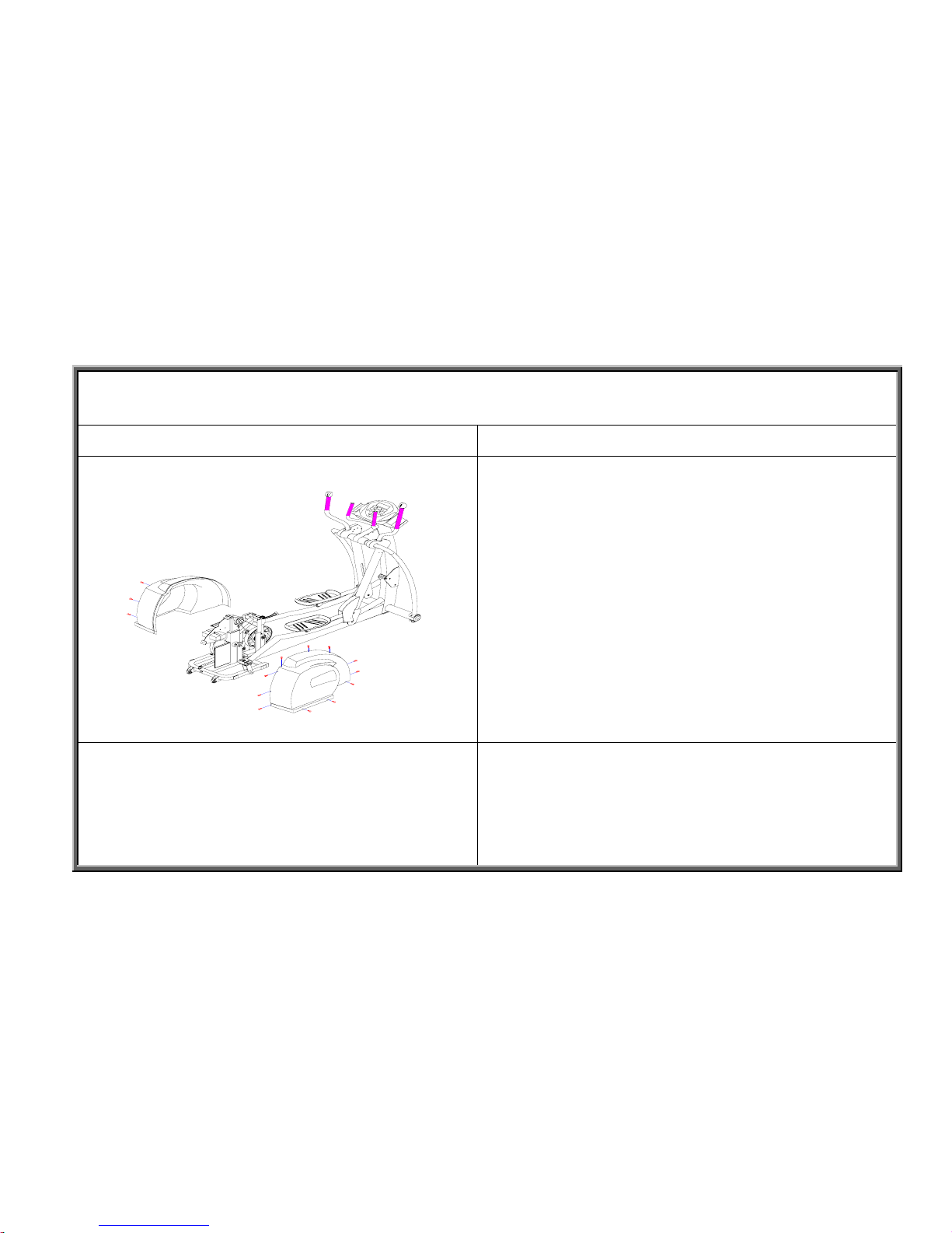
Step 1 Step 2
Remove the 14 mushroom-top Phillips-head screws (A)
from the rear cover, and remove the cover from the unit as
shown.
Remove the mushroom-top Phillips-head metal screws (A)
from the guard panel (A) and remove the finger guard as
shown.
2-3-1
B
SportsArt America
8300 Component Removal and Installation Procedures
Flywheel Removal and Installation
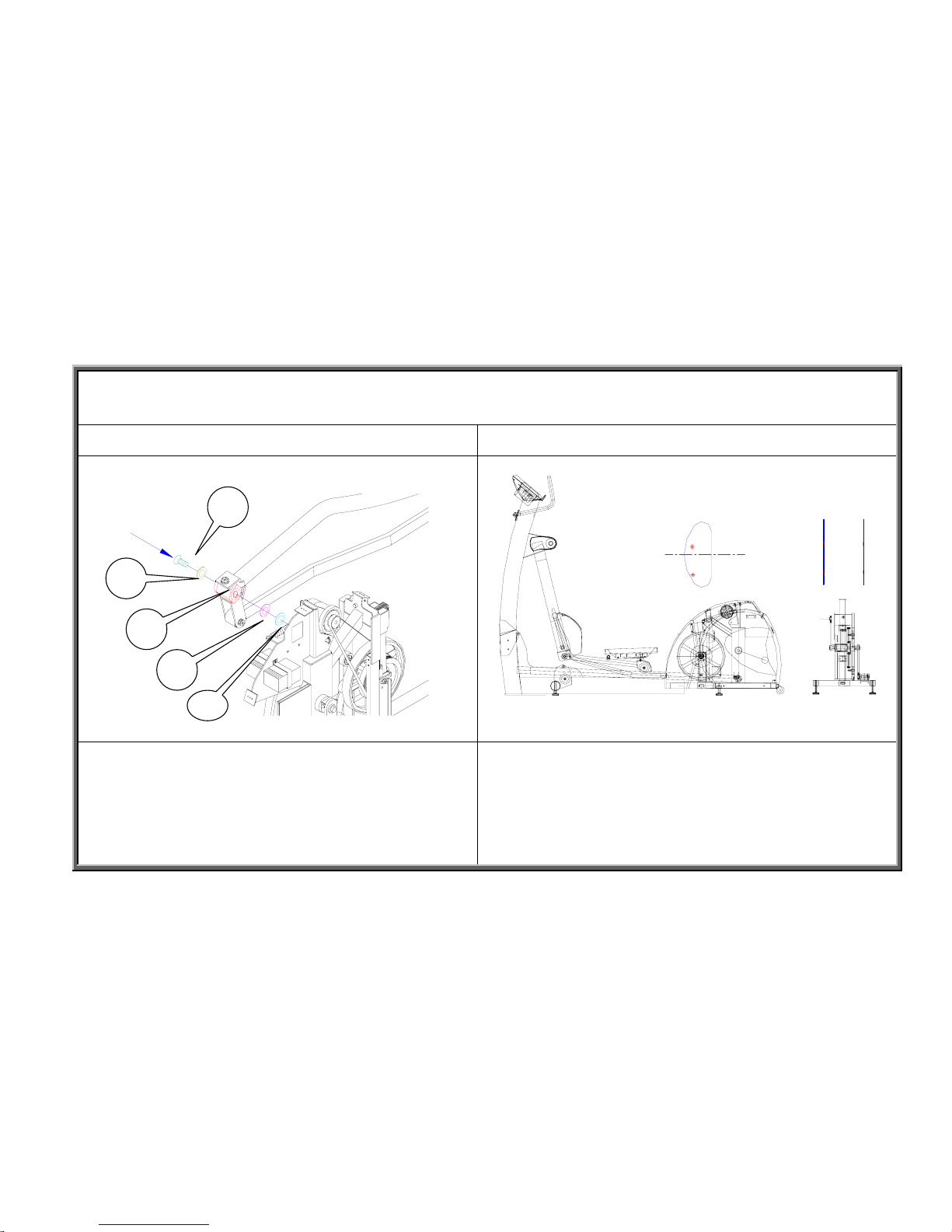
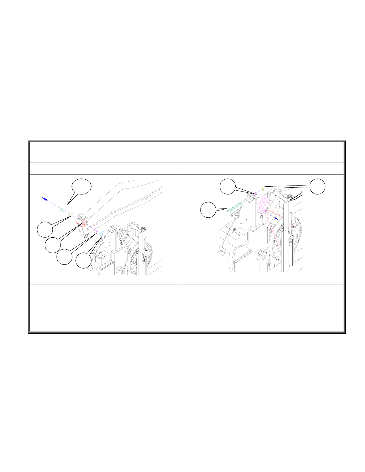
Step 3 Step 4
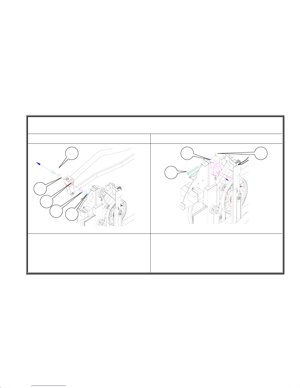
Remove the mushroom-top inner hex screw from the
left-side knuckle, and pull the knuckle off the crank.
Note: If necessary, adjust the knuckle so it slides out easily.
Parts: Spindle washer A; Wave washer B; Knuckle C; Flat
washer D; Mushroom-top inner hex screw
Loosen the nut (C) and screw (A) that attaches the generator
(B) to the unit frame. Then remove the drive belt (440J5).
Note: it is not necessary to totally remove the screw and nut as
shown in the picture. Just loosen them.
2-3-2
A
B
C
D
E B
A
C
SportsArt America
8300 Component Removal and Installation Procedures
Flywheel Removal and Installation
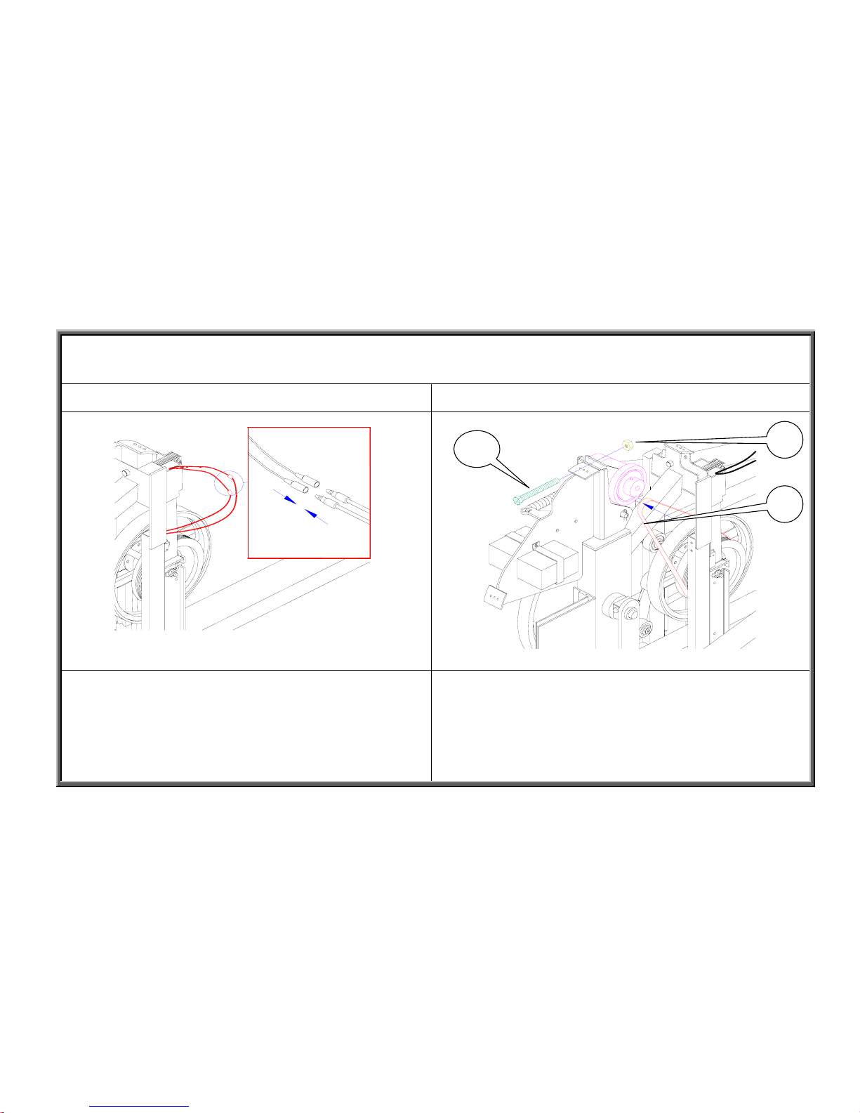
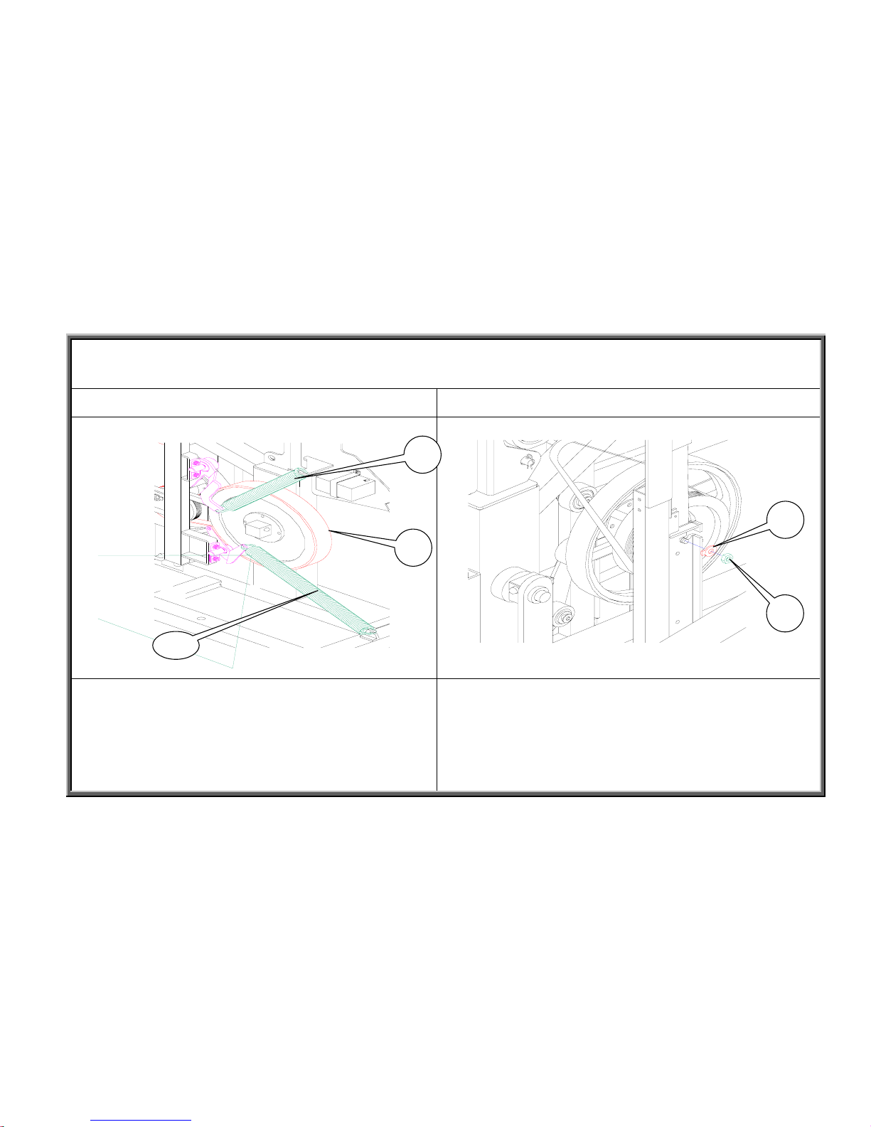
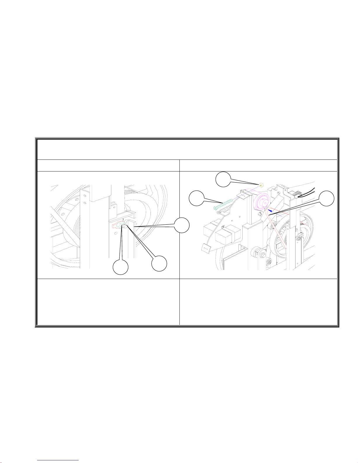
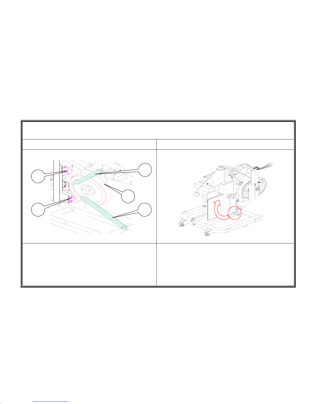
Step 5 Step 6
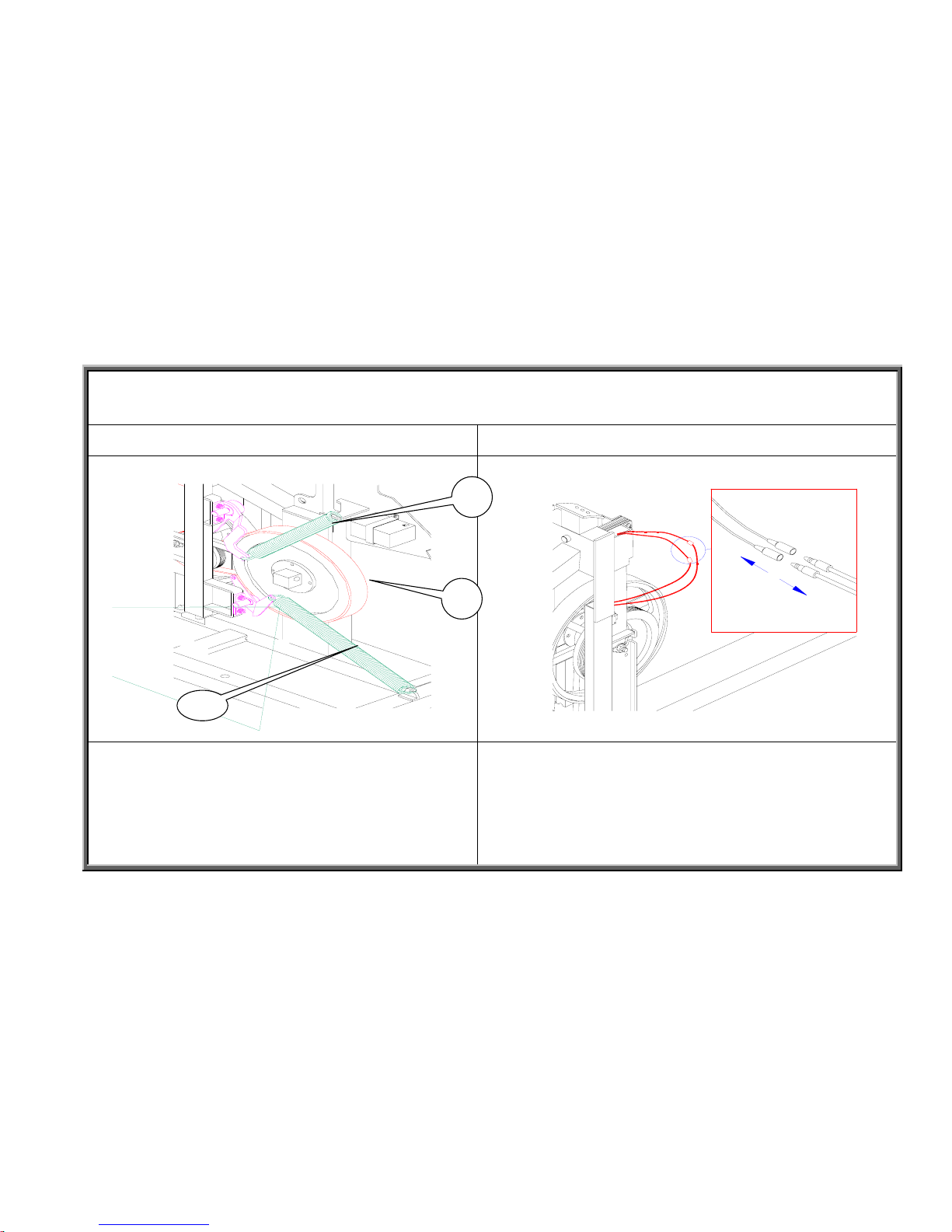
Detach the idler pulley springs (A), and remove the
multi-channel belt (B) (460J7).
Note: When removing idler pulley springs, pull from both
ends to maintain even pressure, preventing the springs
from loosing their flexibility and wearing out early.
Disconnect the magnet wires as shown.
2-3-3
A
B
SportsArt America
8300 Component Removal and Installation Procedures
Flywheel Removal and Installation
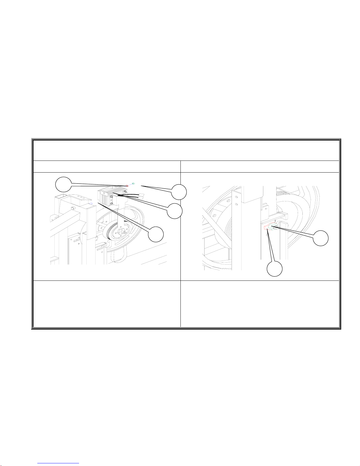
Step 7 Step 8
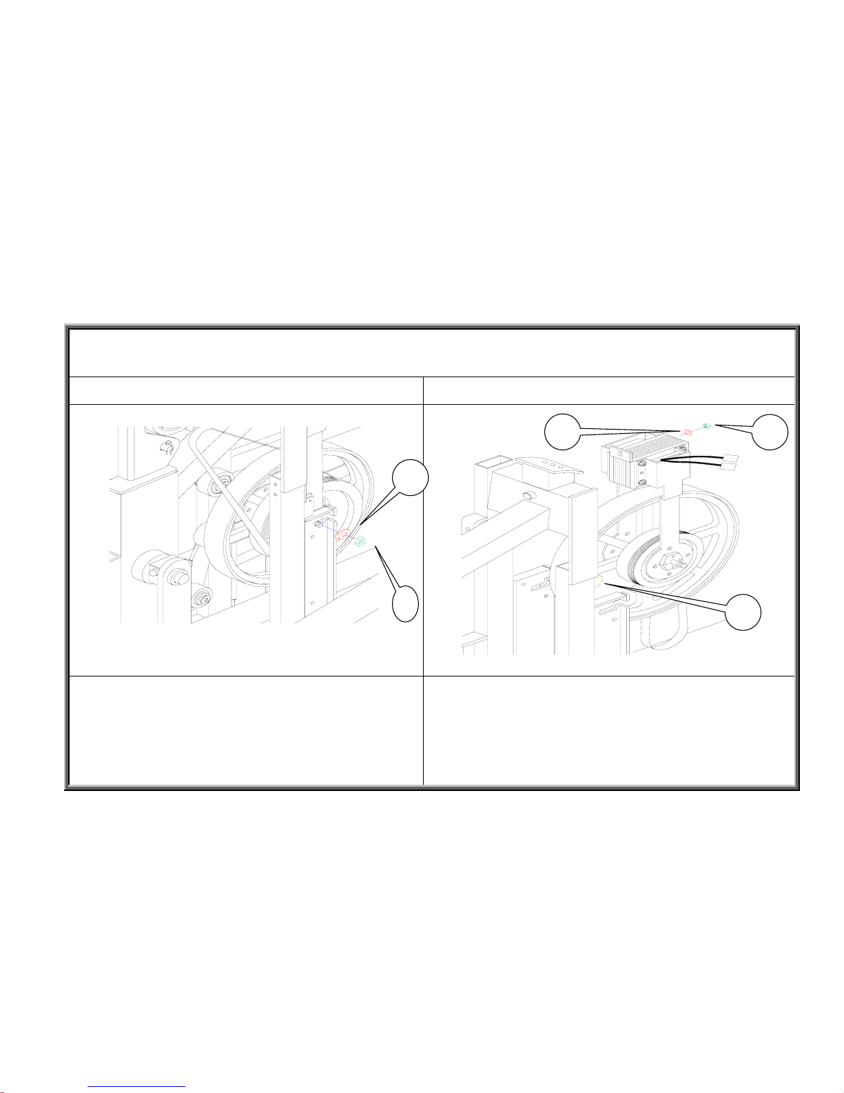
Remove the flywheel nut (B) and washer (A). Remove the nut (B) and washer (C) that secures the flywheel
in place. Then remove the flywheel.
Note: Be careful not to hit the optic sensor (A) when
removing the flywheel.
2-3-4
A
B
A
B
C
SportsArt America
8300 Component Removal and Installation Procedures
Flywheel Removal and Installation
Step 9 Step 10
Insert the axle of the new flywheel into the flywheel
bracket on the frame. Lift the magnet (D) up into the
flywheel attachment screw (C). Install flywheel washer (B)
and nut (A) to the screw.
Put the flywheel washer (B) in place on the axle, with the
washer protrusion facing back, then hand-tighten nut (A) into
place. Press the flywheel toward the back of the unit. Make
sure that the flywheel fits well at the attachment point by the
magnet and at the axle. Tighten the nuts on both sides of the
flywheel and at the attachment screw by the magnet.
2-3-5
A
B
A
B
C
D
SportsArt America
8300 Component Removal and Installation Procedure
Flywheel Removal and Installation
Step 11 Step 12
Connect magnet wires as shown. Put the drive belt (B) (440J5) in place, making sure that it
meshes well on the drive pulley. Then gradually tighten nut (C)
onto the generator screw (A).
Note: Tighten nut (C) just to the point that the belt doesn’t
jump or shudder when the flywheel rotates forward or
backward.
2-3-6
A
C
B
SportsArt America
8300 Component Removal and Installation Procedures
8300 Flywheel Removal and Installation
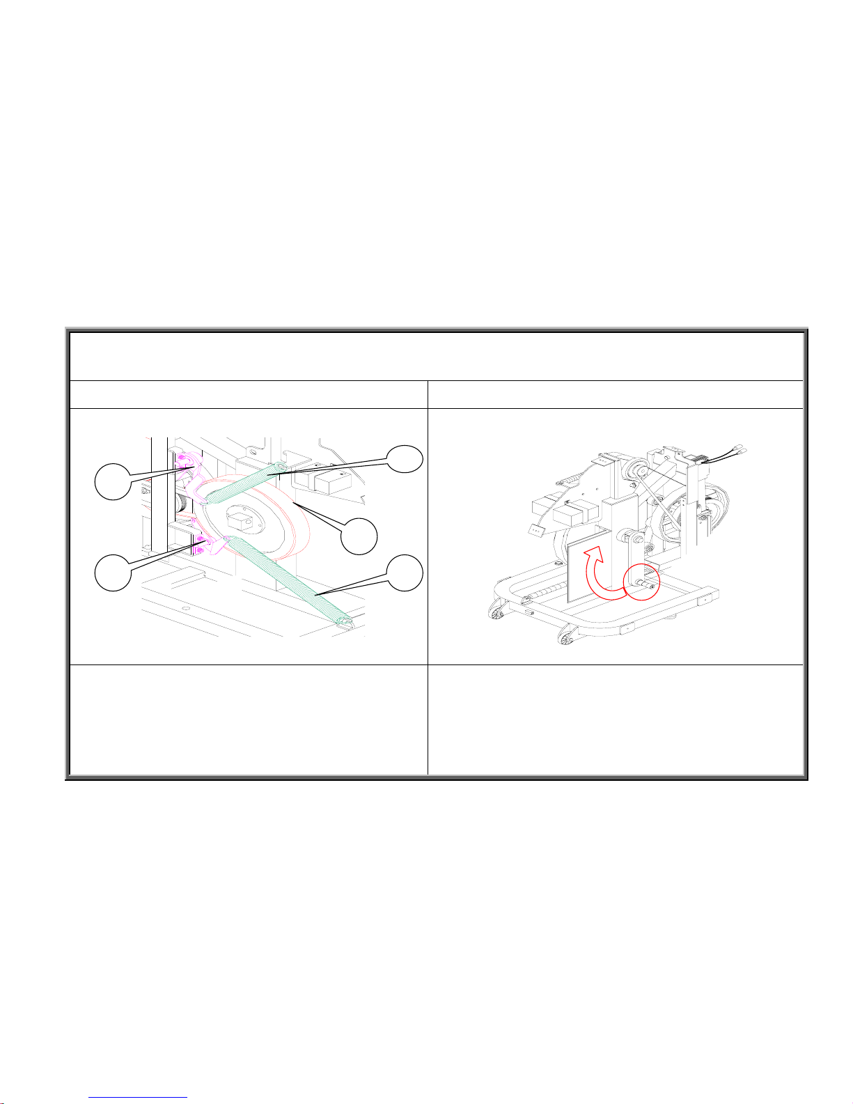
Step 13 Step 14.1
Put belt (C460J7) onto the wheel and adjust the idler pulleys
(A) so the belt sits well. Rotate the flywheel (C) so the belt
meshes, then put idler pulley springs (B) in place.
Note: Pull both ends of the spring to keep the pressure
even and prevent it from losing flexibility.
Inspect the Installation
1. Turn the crank arm: Inspect the flywheel movement.
If not normal, adjust the belt and idler pulleys.
2-3-7
A
A
B
C
SportsArt America
8300 Component Removal and Installation Procedures
Flywheel Removal and Installation
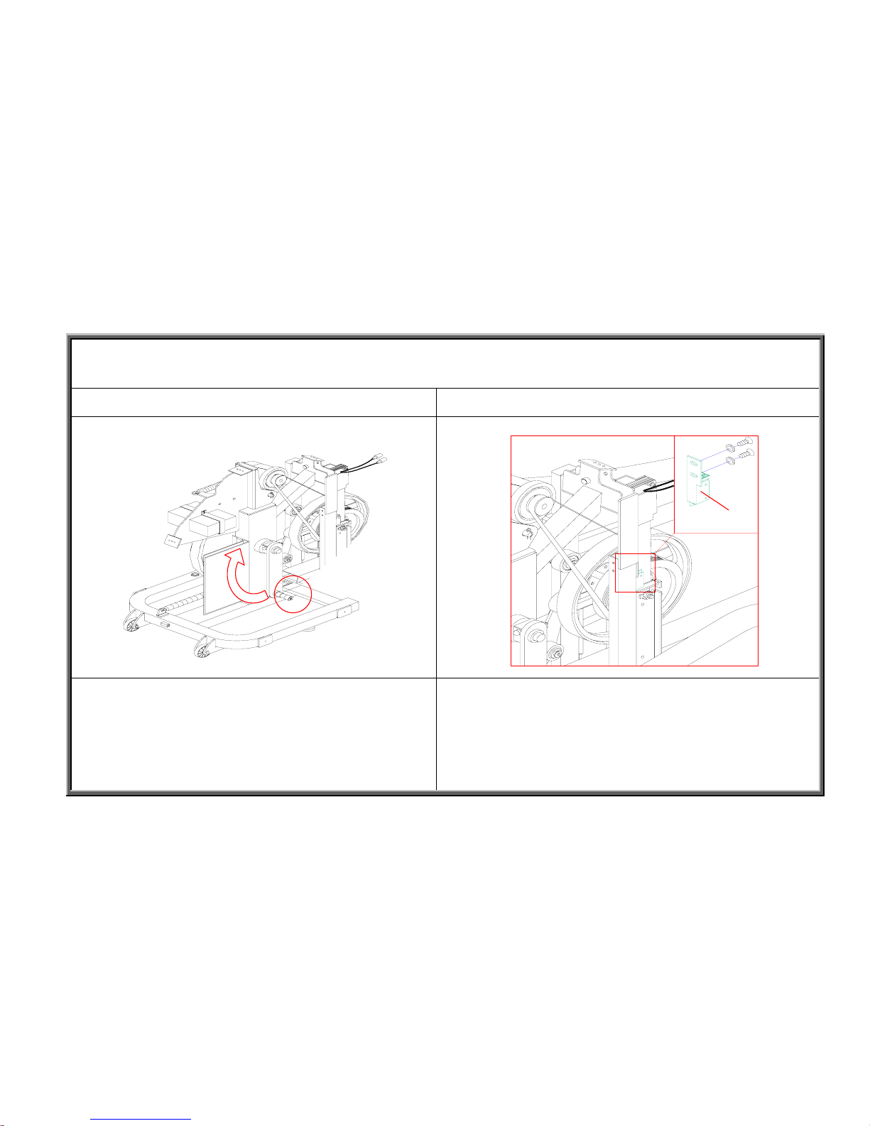
Step 14.2 Step 14.3
Inspect the Installation
2. Rotate the crank and press the LEVEL up key on the
display. Inspect whether resistance increases. If not, inspect
whether wires are properly installed and connected.
Inspect the Installation
3. Rotate the crank and inspect whether a steps-per-minute
value appears on the display. If not, adjust the distance
between the optic sensor and the sticker on the flywheel to
within 3 mm (1/4 inch).
2-3-8
A
SportsArt Industrial
8300 Component Removal and Installation Procedures
Flywheel Removal and Installation
Step 15 Step 16
Install washer (A) and wave washer (B) onto the crank
arm. Then install the left side of the knuckle (C) onto the
crank arm. Finally, put on the flat washer (D), and tighten
the mushroom-head inner hex screw (E).
Note: If the glide rail does not install easily, jiggle the
knuckle.
Put the guard panels in place and screw in their mushroom-top
Phillips-head metal screws.
Note: The flat surface faces the rear; The screw hole
protrusions face the inside of the unit; Screw holes are toward
the lower part of the panel. If installed incorrectly, the unit
covers cannot be installed.
2-3-9
B
C
D
E
SportsArt America
8300 Component Removal and Installation Procedures
Flywheel Removal and Installation
Step 17
Install rear covers onto unit. Tighten the mushroom-head
Phillips screws to complete the job.
Note: The cover attachment plate on the unit frame has
three holes in it, making it easy to screw the cover onto the
wrong hole. As a rule, use the screw hole on the right.
2-3-10

SportsArt America
8300 Component Removal and Installation Procedures
8300 Flywheel Washer Removal and Installation
Step 1 Step 2
Remove the 14 mushroom-top, Phillips-head screws (A)
from the cover, then remove the cover as shown.
Remove the mushroom-top, Phillips-head metal screws (A)
from the finger guard (B). And remove finger guards from both
sides as shown.
2-4-1
B
SportsArt America
8300 Component Removal and Installation Procedures
Flywheel Removal and Installation
Step 3 Step 4
From the left side glide rail, remove the mushroom-top
inner hex screw. Then remove the glide rail.
Note: Adjust the knuckle to remove the glide rail easily.
A = Spindle washer: B=Wave washer; C=Knuckle
D=Flat washer; E=Mushroom-top inner hex screw.
Loosen the outer hex-head screw (A) and nut (C) from the
generator (B) bracket, then remove the drive belt (440J5).
P.S. Loosen the generator screw (A) and nut (C). There’s no
need to take them all the way off.
2-4-2
A
B
C
D
E B
A
C
SportsArt America
8300 Component Removal and Installation Procedures
Flywheel Washer Removal and Installation
Step 5 Step 6
From the left side, remove the idler pulley springs (A) and
the multi-channel belt B(460J7).
P.S. Pull springs from the ends to keep pressure even and
preserve spring life.
Remove the nut (B) and flywheel washer (A).
2-4-3
A
B
B
A
SportsArt America
8300 Component Removal and Installation Procedures
Flywheel Washer Removal and Installation
Step 7 Step 8
Put the flywheel washer (C) in place on the spindle
(B), inserting the protruding part of the washer
toward the rear of the unit. Then hand-screw the nut
(A) in place. Push the flywheel toward the rear of the
unit. Make sure that the washer meshes into the
bracket in the frame. Tighten the nut.
Put generator belt B(440J5) in place. Rotate the flywheel to
make sure that the belt channels mesh in the grooves.
Gradually tighten nylon lock washer (C) onto the bolt (A)
with an inner hex head.
Note: Tighten until the flywheel rotates smoothly in both
directions without jumping.
2-4-4
A
B
C
B
C
A
SportsArt America
8300 Component Removal and Installation Procedures
Flywheel Washer Removal and Installation
Step 9 Step 10.1
Install the multi-channel belt (C460J7) onto the flywheel.
Adjust the idler pulleys (A) so that the idler pulleys ride on
the outside of the belt. Rotate the flywheel to make sure that
the belt and flywheel mesh well. Then put springs (B) into
place.
Note: Pull springs from the ends to maintain even pressure
and prevent springs from wearing out.
Inspect the work:
1. Turn the crank. Inspect whether the multi-channel belt
rotates smoothly.
If not, adjust the multi-channel belt and idler pulleys.
2-4-5
A
A
B
B
C
 Loading...