

SportsArt Fitness 805P, 807P Repair Manual
805P and 807P Elliptical Trainer Repair Manual
USA Version 2
Update: 09-01-04

SportsArt – 805P/807P Repair Manual
805P and 807P Elliptical Trainer Repair Manual
This manual was made through the cooperation of SportsArt personnel in Taiwan and the USA.
In making repair manuals, our goal is to present an accurate, easy-to-use guide for technicians
in the field. We welcome your suggestions and comments.
To make suggestions or comments, please contact Bob Baumgartner. Thank you!
bob@sportsartamerica.com
Tel: 866 709 1750 ext. 115
Fax: 425 488 8155
805P and 807P Elliptical Trainer Repair Manual
USA Version 2
Update: 09-01-04
00

SportsArt – 805P/807P Repair Manual
Table of Contents
Introduction
INTRO.01 - Introduction to the 805P and 807P Elliptical Trainers; 805P and 807P Specifications
INTRO.02 - 805P and 807P Elliptical Trainers (Illustration)
INTRO.03 - 805P and 807P Elliptical Trainers – Front (Illustration)
INTRO.04 - 805P and 807P Elliptical Trainers – Components in Back (Illustration)
INTRO.05 - Display Functions and Windows (Illustration of 805P)
INTRO.06 - Programs (Illustration of 805P)
INTRO.07 - Program Introduction and Operation (Manual, Program)
INTRO.08 - Program Introduction and Operation, Cont. (INTVL Mode)
INTRO.09 - Program Introduction and Operation, Cont. (Heart Rate Control (HRC) Mode)
INTRO.10 - Program Introduction and Operation, Cont. (MODE Function)
INTRO.11 - Program Introduction and Operation, Cont. (STEP, STRIDE, LEVEL, RESET)
INTRO.12 - How to Switch from Metric (KPH) to American Standard (MPH); How to Input User Weight
How to Operate Display LCD Test; How to View Mileage in Memory; How to Erase Mileage in Memory
INTRO.13 - 805P and 807P Operation Diagram
Display
DISPLAY.01 - 805P Display Board Wire Connections
DISPLAY.02 - 805P Display Board Component Locations – Back Side
DISPLAY.03 - 805P Display Board Component Locations – Front Side
DISPLAY.04 - 805P Display Board Indicator Definitions
CONTENTS.01

SportsArt – 805P/807P Repair Manual
Table of Contents (Cont.)
Drive Board
DRIVE.01 - 805P/807P Drive Board Connections
DRIVE.02 - 805P/807P Drive Board Component Illustration
DRIVE.03 - 805P/807P Drive Board Indicator Locations and Definitions – LED 1, 2, 5, 7
DRIVE.04 - 805P/807P Drive Board Indicator Locations and Definitions – LED 3, 4, 6, 8
DRIVE.05 - 805P/807P Drive Board Indicator Locations and Definitions – LED 9, 10, 11, 12
Power
POWER.01 – 805P/807P Elliptical Trainer Power Up
POWER.02 – Illustration of the Power Up Process
POWER.03 – 805P/807P Drive Board VCC Circuit Power Test
POWER.04 – Drive Board VCC Power Test Procedure; Drive Board VCC Power Output Test
POWER.05 – 805P Display Board VCC Power Test
POWER.06 – Display Board VCC Power Test Procedure
POWER.07 – Transformer Primary Voltage Test (Illustration)
POWER.08 – Transformer Primary and Secondary Tests (Illustration)
POWER.09 – Transformer Primary Test Procedure; Transformer Secondary Test Procedure
CONTENTS.02

SportsArt – 805P/807P Repair Manual
Table of Contents (Cont.)
Optic Sensor
OPTIC.01 - Optic Sensor Operation
OPTIC.02 - Optic Sensor Signal Illustration
OPTIC.03 - Optic Sensor Malfunction; Troubleshooting
OPTIC.04 - Optic Sensor Signal LED and Test Location
OPTIC.05 - Optic Sensor Tests (Illustration)
OPTIC.06 - Optic Sensor Power (VCC) Test; Optic Sensor Signal (CLK) Output Test
Resistance
LEVEL.01 - Resistance Operation – Diagram and Explanation
LEVEL.02 - Optic Sensor Operation in Resistance (Illustration)
LEVEL.03 - Resistance Malfunction
LEVEL.04 - Resistance Voltage Test at the Drive Board
LEVEL.05 - Drive Board Resistance Voltage Test Procedure
LEVEL.06 - Magnet OHM Test
LEVEL.07 - Magnet OHM Test Procedure; Magnet Current Leakage Test
LEVEL.08 - Drive Board VDD Voltage Test
CONTENTS.03

SportsArt – 805P/807P Repair Manual
Table of Contents (Cont.)
Stride
STRIDE.01 - Stride Operation Diagram
STRIDE.02 - Stride Operation Explanation
STRIDE.03 - Stride Operation Illustration
STRIDE.04 - Stride LED Indicators on the Drive Board
STRIDE.05 - Stride Motor Protective Function
STRIDE.06 - Stride Motor Protection OVR LEDs
STRIDE.07 - Stride System Troubleshooting
STRIDE.08 - Stride Motor Voltage Test (Illustration); Stride Motor Voltage Test Procedure
STRIDE.09 - Stride VR Voltage Test (Illustration); Stride VR Voltage Test Procedure
STRIDE.10 - Stride Motor and VR Voltage Test Summary (Illustration); Test Procedure
STRIDE.11 - Stride Motor and VR Calibration
STRIDE.12 - Stride Motor and VR Calibration (Continued)
STRIDE.13 - Stride Motor and VR Calibration (Continued)
STRIDE.14 - Stride Motor and VR Calibration (Continued)
Polar
POLAR.01 - 805P Elliptical Tr ainer Polar Heart Rate Function
POLAR.02 - Polar Receiver Wire Connections, Transmitter Signal Transmission
POLAR.03 - Polar Heart Rate Test Procedure
CONTENTS.04

SportsArt – 805P/807P Repair Manual
Table of Contents (Cont.)
HTR Function
HTR.01 – 807P Elliptical Trainer Heart Touch Rate Function
HTR.02 – HTR Wire Connections
HTR.03 – Heart Rate Board Diagram
HTR.04 – HTR and HR Malfunction Troubleshooting; Troubleshooting Chart
Key
KEY.01 - Key and Switch Operation – Diagram; Key and Switch Operation - Explanation
KEY.02 - Switch Operation Illustration
KEY.03 - Key and Switch Malfunctions; Key and Switch Troubleshooting
KEY.04 - Display Key Illustration
KEY.05 - Key Test Illustration
KEY.06 - Key Test Procedure
Troubleshooting
TROUBLE.01 - Error Codes
TROUBLE.02 - Electronic Malfunctions
TROUBLE.03 - Display Does Not Light Up
TROUBLE.04 - Display Board VCC Test
TROUBLE.05 - Drive Board VCC Power Test
CONTENTS.05

SportsArt – 805P/807P Repair Manual
Introduction
INTRO.01 - Introduction to the 805P and 807P Elliptical Trainers; 805P and 807P Specifications
INTRO.02 - 805P and 807P Elliptical Trainers (Illustration)
INTRO.03 - 805P and 807P Elliptical Trainers – Front (Illustration)
INTRO.04 - 805P and 807P Elliptical Trainers – Components in Back (Illustration)
INTRO.05 - Display Functions and Windows (Illustration of 805P)
INTRO.06 - Programs (Illustration of 805P)
INTRO.07 - Program Introduction and Operation (Manual, Program)
INTRO.08 - Program Introduction and Operation, Cont. (INTVL Mode)
INTRO.09 - Program Introduction and Operation, Cont. (Heart Rate Control (HRC) Mode)
INTRO.10 - Program Introduction and Operation, Cont. (MODE Function)
INTRO.11 - Program Introduction and Operation, Cont. (STEP, STRIDE, LEVEL, RESET)
INTRO.12 - How to Switch from Metric (KPH) to American Standard (MPH); How to Input User Weight
How to Operate Display LCD Test; How to View Mileage in Memory; How to Erase Mileage in Memory
INTRO.13 - 805P and 807P Operation Diagram
INTRO.00
SportsArt – 805P/807P Repair Manual – Introduction
Introduction to the 805P and 807P Elliptical Trainers
Some of the first elliptical trainers with automatic stride adjustment, the 805P and 807P provide a gentle,
full-body workout. 805P offers user convenience –automated stride and resistance adj ustment on the display
and handlebars – and a full array of possibilities, including heart rate control, three programs, intervals and
manual operation, plus Polar heart rate feedback, step count, calorie expenditure, and steps per minute.
807P offers all this, plus heart touch rate (HTR) handlebars and a dot matrix feedback display screen.
805P and 807P Specifications
Item Range Notes
Power Plug in type N. America: 110 VAC
Fuse 1 Amp slow blow Size: 6mm x 32mm
Display 805P: Liquid Crystal Display; 807P: Dot Matrix See INTRO.12 for test mode.
Resistance (LEVEL) LEVEL 1-14; Control on handle switch and display key
Stride 450-650 mm; 17.0-26.0 inch; Display and handle control Units: Metric or US. See INTRO.12
INTV Interval program For operation, see INTRO.08.
PROGRAM Program 1, 2, 3 For operation, see INTRO.07.
Heart Rate (HR) 805P: Polar + HRC; 807P: Polar + HRC + HTR For operation, see INTRO.09.
Weight Limit 300 pounds
Dimensions L: 77”, W: 22”; H: 72”
Net Weight 172 pounds
Home Warranty 2 year parts, 1 year labor
Com. Warranty 1 year parts and labor Limited use: 4 hours per day
INTRO.01
SportsArt – 805P/807P Repair Manual – Introduction
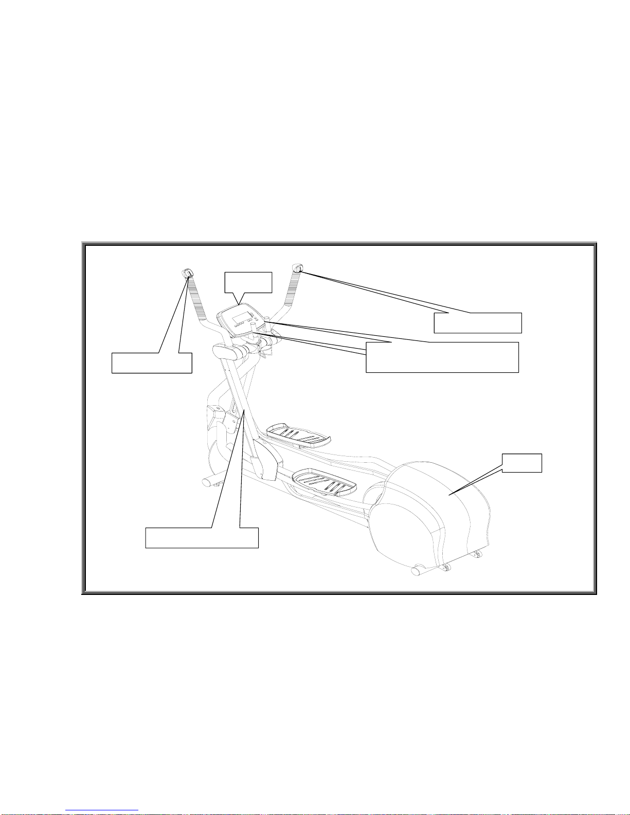
805P and 807P Elliptical Trainers
INTRO.02
Display
Stride Support Arm
Cover
Stride Switch
Level Switch
HTR 心跳握
Stationary Handlebars (805P)
HTR Handlebars (807P)
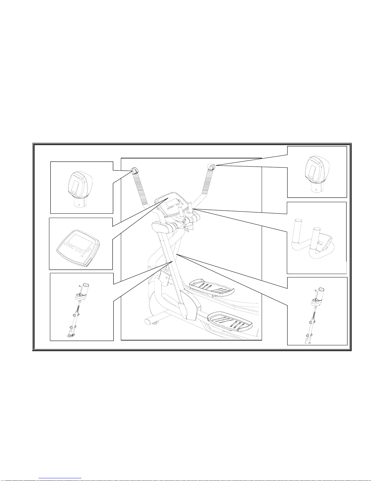
SportsArt – 805P/807P Repair Manual – Introduction
Electronic Components in Front
INTRO.03
Stride Motor (Right)
Stride Motor (Left)
Stride Switch
Level Switch
Display
Stationary
Handlebars
HTR – 807P only
SportsArt – 805P/807P Repair Manual – Introduction
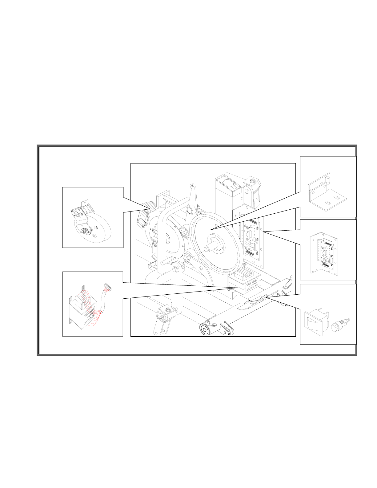
805P and 807P Elliptical Trainers - Components in Back
INTRO.04
Magnet & Flywheel
Drive Board
Transformer
Optic Sensor
On/Off Switch &
Fuse Holder
SportsArt – 805P/807P Repair Manual – Introduction
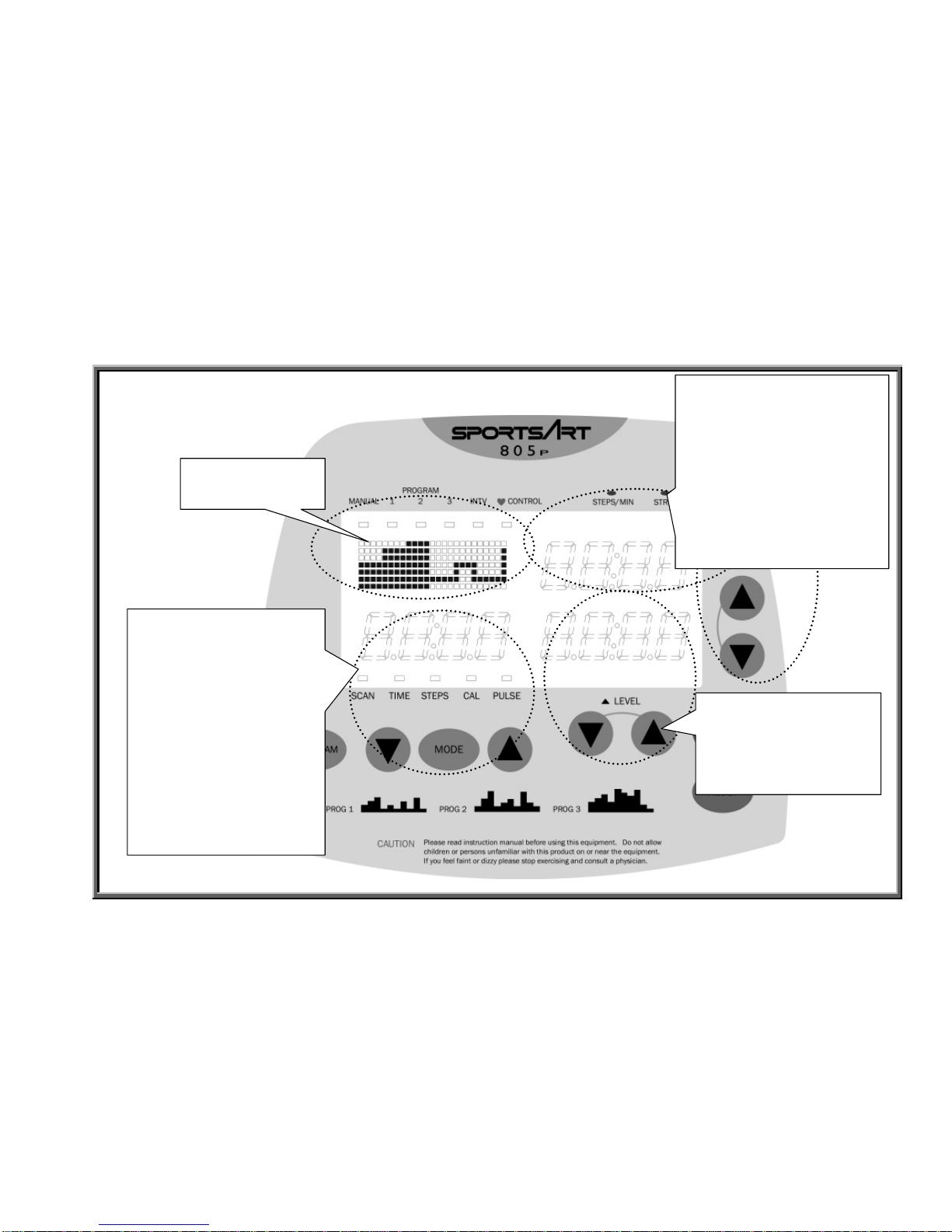
Display Functions and Windows
INTRO.05
Level Window
Press LEVEL UP or
DOWN key to increase
or decrease resistance.
STEPS/MIN & STRIDE
Window
STEPS/MIN indicator lights
when steps per minute are
showing in the window.
STRIDE indicator lights
when the stride setting is
shown.
Mode Window and
Indicators
SCAN, TIME, STEPS,
CAL, PULSE indicators
light to indicate the
function showing in the
window.
Press MODE key to
change modes. Press
MODE UP or DOWN
keys when prompted.
Program Window
and Indicators
SportsArt – 805P/807P Repair Manual – Introduction
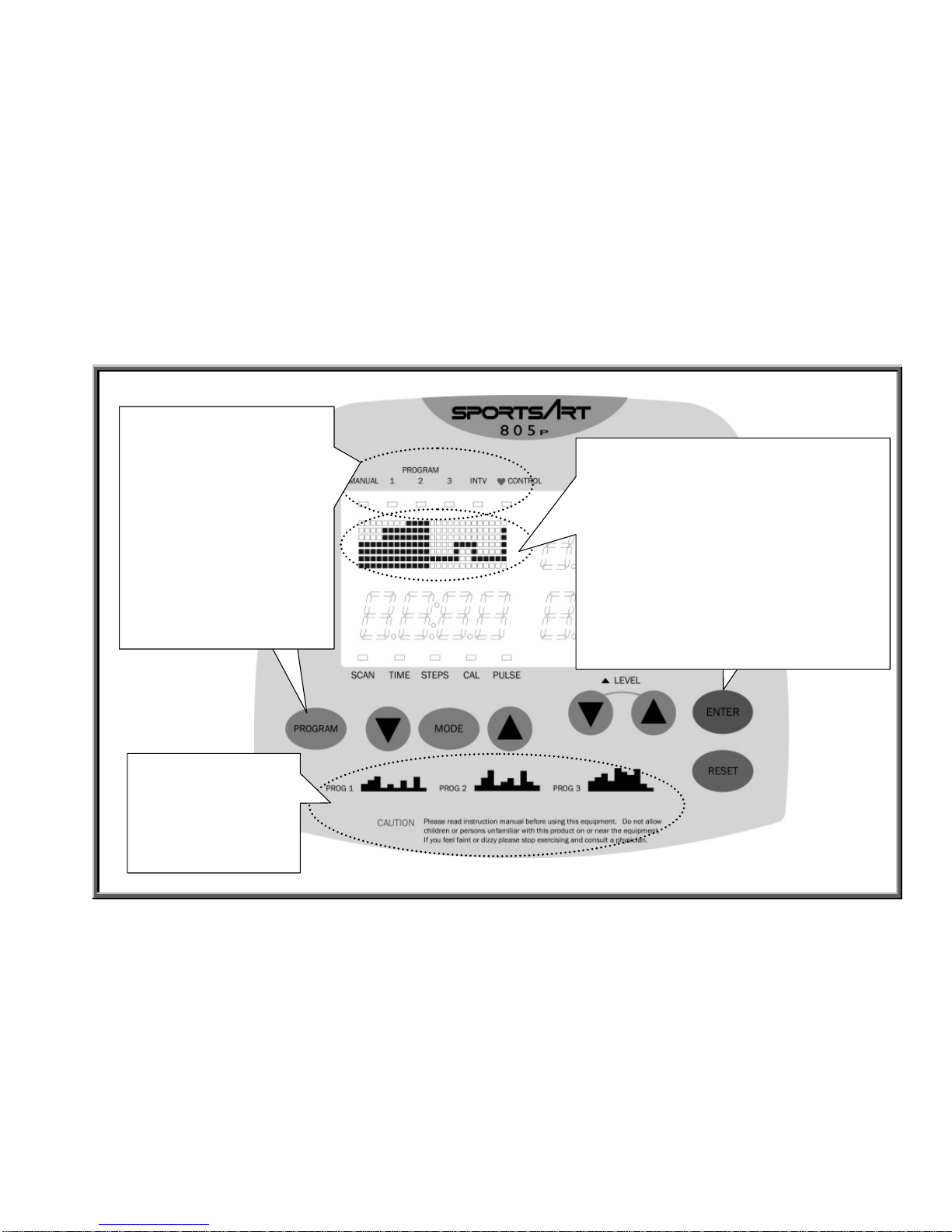
Programs
INTRO.06
Press ENTER
key to confirm
your selections.
(2) Press ENTER key (below) to confirm
your selection.
For INTV mode, follow prompts.
For heart rate control, wear your Polar
heart rate strap and follow prompts.
During an exercise program, the screen
appears as shown at left. Your progress is
marked by the advancement of colored
spaces.
(1) Program indicators light
to express which program
mode is operating. Each
time the PROGRAM key is
pressed, the program
indicator light advances to
the right.
Press PROGRAM key until
the indicator under your
preferred program mode
lights.
Exercise program
illustrations appear at
right. Height indicates
resistance: The
higher, the more
resistance.
SportsArt – 805P/807P Repair Manual – Introduction
Program Introduction and Operation
1. Manual Mode
Manual mode allows direct control of resistance and stride settings.
Operation: (a) Press the PROGRAM key until the MANUAL indicator lights.
(b) Press the ENTER key to confirm your choice. The main window will show “MAN’L”.
(c) Press LEVEL and STRIDE keys to set resistance and stride settings.
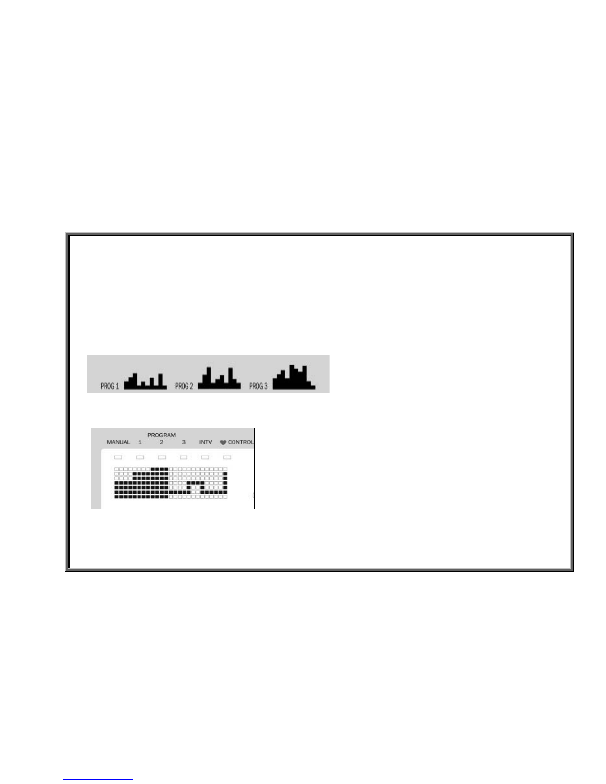
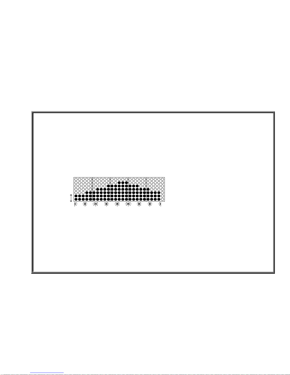
2. Program Mode
Built-in exercise programs provide the following workout routines.
Illustration height represents resistance: the higher the column, the more resistance. (One dot (below)
represents two resistance levels.) Horizontal length represents time. Once in exercise program mode,
the main window shows a picture like the one below.
The illustration represents an exercise course. The user’s progress is tracked by the coloring of columns:
Solid color columns mark an area already traveled; Uncolored columns represent an area not yet traveled.
INTRO.07
SportsArt – 805P/807P Repair Manual – Introduction
Operation
(a) Press the PROGRAM key until your preferred program appears in the main window.
Program 1 appears as “PRO:1”; Program 2: “PRO:2”; Program 3: “PRO:3”.
(b) Press the ENTER key to confirm your selection. Press MODE<▲> or <▼> key to select
a time length.
(c) Press the ENTER key to confirm your selection. The PROGRAM pattern appears and the
program begins operating. Start exercising.
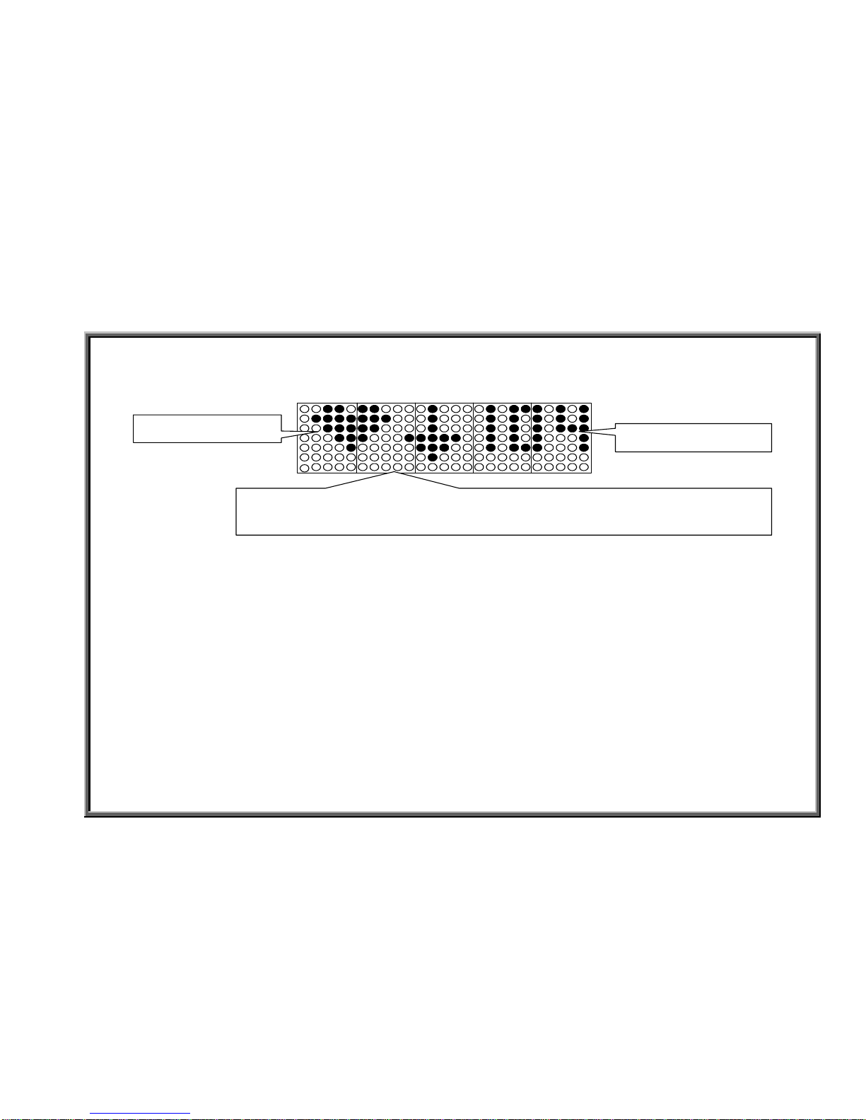
3.INTV Mode
Interval mode allows the user to create a unique exercise program -- all under microcomputer control.
One interval includes eight segments, SEG1~SEG8. The user establishes LEVEL and TIME values.
An eight-segment interval session might appear on the display like the following example.
SEG1SEG2SEG3SEG4 SEG7SEG6 SEG8SEG5
LEVEL
Operation: (a) Press the PROGRAM key until the INTV indicator lights. “INTV” appears in the
main window.
(b) Press the ENTER key to confirm your selection. The main window will show “SEG1”. The
MODE window TIME indicator will light.
(c) Press the MODE UP or DOWN key to select a time length. Press the ENTER key to confirm
your choice.
(d) Press the LEVEL UP or DOWN key to select a resistance level. Press the ENTER key to confirm
your choice.
(e) Set all other segment resistance levels and time periods by following steps c-d again.
(f) The interval program will operate after all segments are programmed.
INTRO.08

SportsArt – 805P/807P Repair Manual – Introduction
4. Heart Rate Control (HRC) Mode
HRC mode allows users to exercise at an optimal heart rate for either cardio conditioning or fat loss.
In heart rate control mode, the unit automatically adjusts the resistance level to keep the user’s heart rate
at a pre-set target. The pre-set target is based on a formula for optimum fat burn and cardio conditioning
rates.
220 – (your age) = x
x * 65% = (your fat burn target heart rate)
x * 80% = (your cardio conditioning target heart rate)
So, for a 37 year old person, the formula works out as follows: 220 – 37 = 183.
Optimal fat burn heart rate: 183 * .65 = 119.
Optimal cardio conditioning heart rate: 183 * .80 = 146. The 805P figures this out for you.
Operation: (a) Press the PROGRAM key until the Heart Rate CONTROL indicator lights. The main
window shows “HRC”.
(b) Press the ENTER key. The program window shows “FAT” or “CARDIO”.
(c) Press MODE<▲> or <▼> key until your preferred mode, FAT or CARDIO, appears. Press ENTER
key to confirm your choice.
(d) “AGE35” appears in the mode window. Press MODE<▲> or <▼> keys until your age appears.
Press ENTER key to confirm your choice.
(e) “MODIFY” appears in the program window and the PULSE indicator
lights; MODE window shows the heart rate value. Press MODE<▲> or <▼> key to modify your target
heart rate. When the display shows your preferred target heart rate, press <ENTER> to confirm your choice.
(f) “MODIFY” appears in the program window and the TIME indicator lights. “5:00” appears in the mode
window.
Press MODE <▲> or <▼> key until your preferred workout period appears. Press ENTER to confirm your
choice. (Continued on following page.)
INTRO.09
SportsArt – 805P/807P Repair Manual – Introduction
(g) The main window will show the HRC pattern below and the unit will start operating in HRC mode.
Note:
HRC mode works only if the user is wearing a Polar heart rate strap. If the Polar strap loses contact,
the display will show “NO ♥,” beep once, and return to MANUAL mode.
5. MODE Function
Mode provides two functions: (1) in operation, press the MODE key to toggle between TIME, STEPS, CAL,
PULSE functions. (2) Mode also allows a time or step countdown. For example, in MANUAL mode, press
the MODE key until the TIME indicator lights. Press the MODE up key to 10:00, for ten minutes. Then press
the MODE down key. The display time reading will count down from 10:00, to 9:59, 9:58, 9:57.... At 0, the
display beeps and begins counting up, 1,2,3….
INTRO.10
Target heart rate
HRC mode symbol
Level operation
Down Arrow=>Resistance is decreasing. Up Arrow =>Resistance is increasing.

SportsArt – 805P/807P Repair Manual – Introduction
6. STEP Function
The step function shows unit speed measured as steps per minute. It operates automatically. Exercise on the unit.
The STEPS/MIN indicator lights, and the STEPS/MIN window shows the STEPS/MIN value. STEPS/MIN and STRIDE
indicators toggle every six seconds.
7. STRIDE Function
The stride function shows the stride length setting and allows for stride adjustment. When the display STRIDE window lights,
the STRIDE window shows the stride value. Stride range: 450-650 mm (17.0-26.0 inches); Stride and step indicators toggle
every six seconds.
Operation: (a) Press STRIDE UP key on the display or handlebar until the STRIDE window shows 450 mm (17.0 inches). The
STRIDE indicator lights. The stride linkage moves to the highest position on the stride support arm. (b) Press STRIDE
DOWN key on the display or handlebar until the STRIDE window shows 650 mm (26.0 inches). The stride indicator lights. The
stride linkage moves to the lowest position on the stride support arm.
8. LEVEL Function
The level function shows and sets the resistance value.
Operation: (a) Press LEVEL DOWN key until the LEVEL window shows 1. Exercise on the unit. Resistance is at
the lowest level. (b) Press LEVEL UP
key until the LEVEL window shows 14. Exercise on the unit. Resistance is at the highest
level.
9. RESET Function
Reset clears all functions except STRIDE to 0.
Operation: Press the RESET key. The display beeps once, and all functions except stride show 0.
INTRO.11

SportsArt – 805P/807P Repair Manual – Introduction
How to Switch from Metric (KPH) to American (MPH) Standard; Also, How to Input User Weight
Operation: (a) Press the MODE key for three seconds. The program window shows “SET”.
(b) Press the ENTER key. The program window will show “KG” or “LB”.
(c) Press MODE DOWN or UP key to toggle between KG and LB.
(d) When your preferred unit of measurement appears, press the ENTER key to confirm your choice.
(e) The program window shows a weight, for example, 150 LB. Press MODE UP or DOWN key to find
your weight. Press the ENTER key to confirm your choice.
How to Operate Display LCD Test
The display test allows easy inspection of all display marks.
(a) Turn on the unit and don’t press any other keys.
(b) Simultaneously press the STRIDE DOWN and ENTER keys.
(c) Display LEDs light in a sequential order, then a prompt appears: “KEY 1”.
(d) When “KEY 1” appears, press the PROGRAM key.
(e) When “KEY 2” appears, press the MODE DOWN key.
(f) Press the following keys when prompted. “KEY 3” = MODE key; “KEY 4” = MODE UP key;
“KEY 5” = LEVEL DOWN key; “KEY 6” = LEVEL key; “KEY 7” = LEVEL UP key; KEY 8 = STRIDE UP
key; “KEY 9” = STRIDE key; “KEY 10” = STRIDE DOWN key; “KEY 11” = ENTER key; “KEY 12” = RESET
key. (g) The display will show “OK.”
How to View Mileage In Memory; How to Erase Mileage Memory
(a) Turn on the unit and don’t press any other keys.
(b) Simultaneously press LEVEL DOWN+ENTER keys. Mileage value will appear on the display.
(c) Simultaneously press LEVEL UP+ENTER keys. “OK” appears to indicate that mileage memory
has been erased.
INTRO.12

SportsArt – 805P/807P Repair Manual – Introduction
805P and 807P Operation Diagram
Transformer
Magnet
STRIDE
Motor,VR
(Left)
HTR Board
Display
Drive Board
Optic Sensor
LEVEL
Switch
STRIDE
Switch
STRIDE
Motor,VR
(Right)
Power
Cable
FUSE
Switch
POLAR
Receiver
Soft Keys
HTR
Handlebar
(Left, Right)
CLK
Voltage
Transformer
Voltage VR VR
STRIDE
LEVEL
KEY
PULSE
INTRO.13

SportsArt – 805P/807P Repair Manual
Display
DISPLAY.01 - 805P Display Board Wire Connections
DISPLAY.02 - 805P Display Board Component Locations – Back Side
DISPLAY.03 - 805P Display Board Component Locations – Front Side
DISPLAY.04 - 805P Display Board Indicator Definitions
DISPLAY.00
SportsArt – 805P/807P Repair Manual - Display
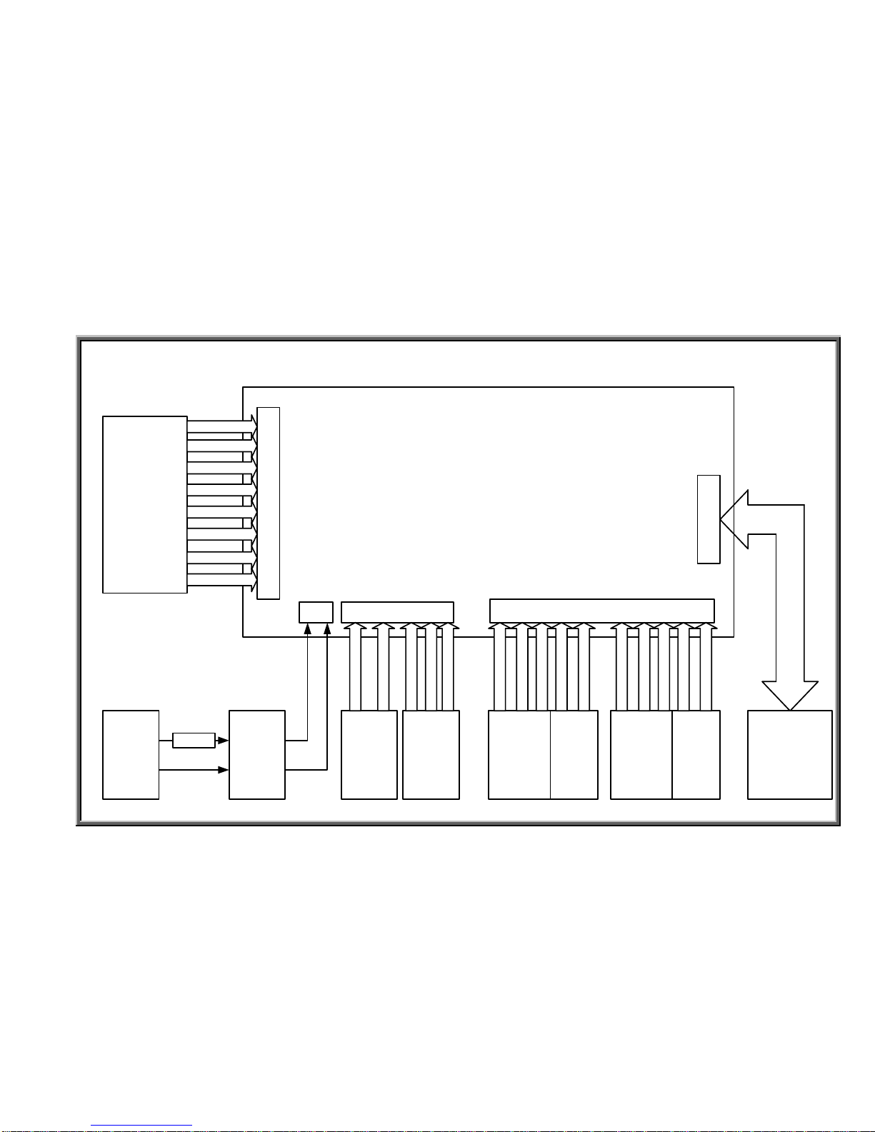
805P Display Board Wire Connections
DISPLAY.01
Drive Board
Handlebar Switches
Polar
Receiver
Note: 807P wire connections are similar with one
exception. HTR handlebar wires (not shown) and
the polar receiver board (above) plug into an HTR
board (not shown). The HTR board plugs into
CON1 on the 807P display.
SportsArt – 805P/807P Repair Manual - Display
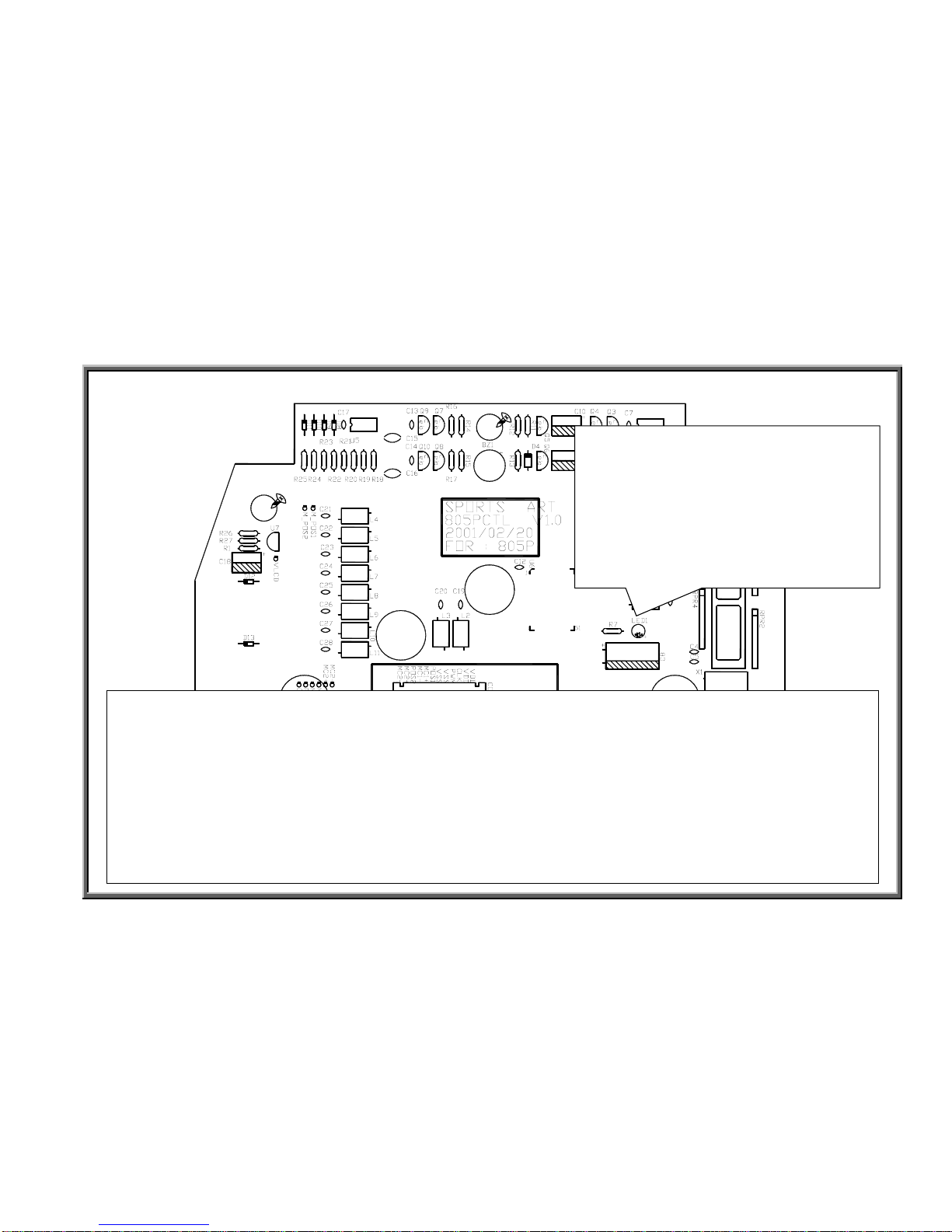
805P Display Board Component Locations – Back Side
DISPLAY.02
SportsArt – 805P/807P Repair Manual - Display
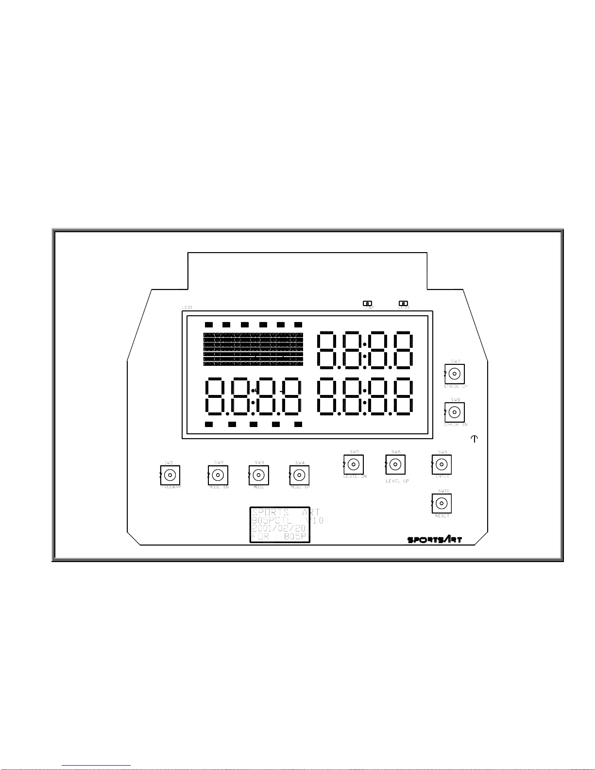
805P Display Board Component Locations – Front Side
DISPLAY.03
SportsArt – 805P/807P Repair Manual - Display
805P Display Board Indicator Definitions
DISPLAY.04
LED1 Power Indicator
ÎLit means that the display is receiving
5 VDC power supply. The display should
light up. This power circuit is labeled
VCC.
ÎNot lit means that the display is not
receiving 5 VDC power supply, VCC
circuit power. The display will not light up.
807P Display Board Indicator Definitions
Led13 Power Indicator (top center, not shown)
ÎLit means that the display is receiving 5 VDC power supply. The display should light up. This power circuit
is labeled VCC.
ÎNot lit means that the display is not receiving 5 VDC, VCC circuit power. The display will not light up.
Led14 CLK (optic sensor) Indicator (right side, not shown)
Flashes when optic sensor signal enters display at low speed. Appears to remain lit when signal enters at
high speed.

SportsArt – 805P/807P Repair Manual
Drive Board
DRIVE.01 - 805P/807P Drive Board Connections
DRIVE.02 - 805P/807P Drive Board Component Illustration
DRIVE.03 - 805P/807P Drive Board Indicator Locations and Definitions – LED 1, 2, 5, 7
DRIVE.04 - 805P/807P Drive Board Indicator Locations and Definitions – LED 3, 4, 6, 8
DRIVE.05 - 805P/807P Drive Board Indicator Locations and Definitions – LED 9, 10, 11, 12
DRIVE.00
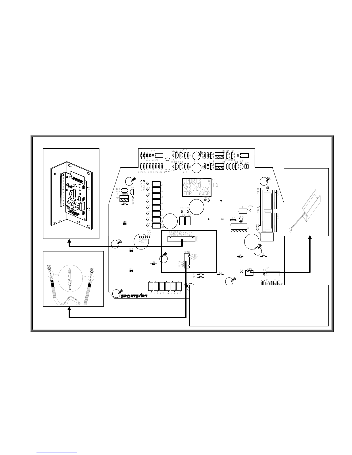
SportsArt – 805P/807P Repair Manual – Drive Board
805P/807P Drive Board Connections
Drive Board
Transformer
Display
Board
Power
Cord
Switch
FUSE
Magnet
Optic
Sensor
VR2
Incline
Motor
Set 2
VR1
Incline
Motor
Set1
WHITE
GREY
RED
BROWN
BLACK
YELLOW
ORANGE
PURPLE
BLUE
GREEN
CN3
BLUE
BLUE
RED
GREEN
BLACK
RED/BLUE
RED/BLUE
YELLOW
YELLOW
WHITE
WHITE
BLACK
BLACK
CN1 CN4
CN5
CN5
18-PIN CABLE
DRIVE.01
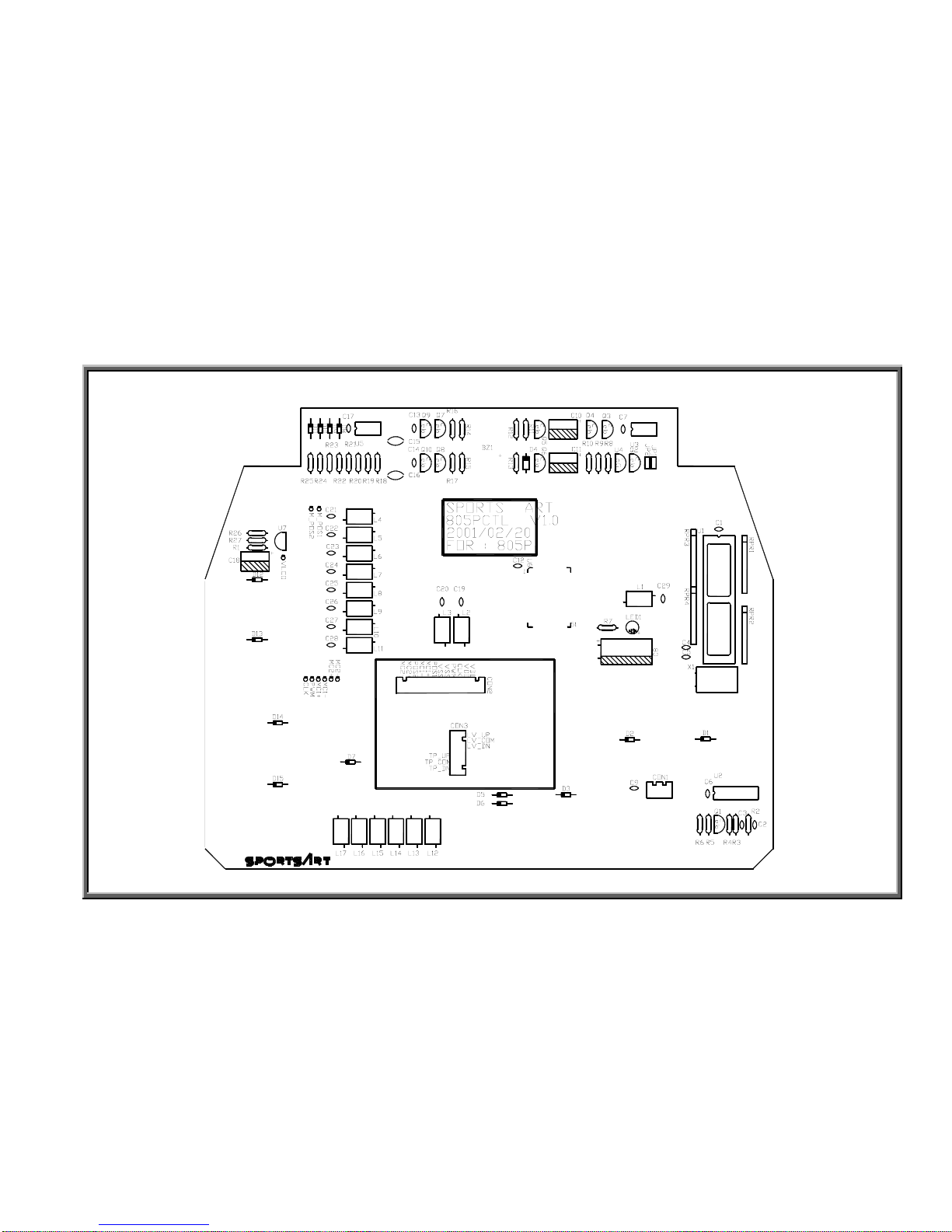
SportsArt – 805P/807P Repair Manual – Drive Board
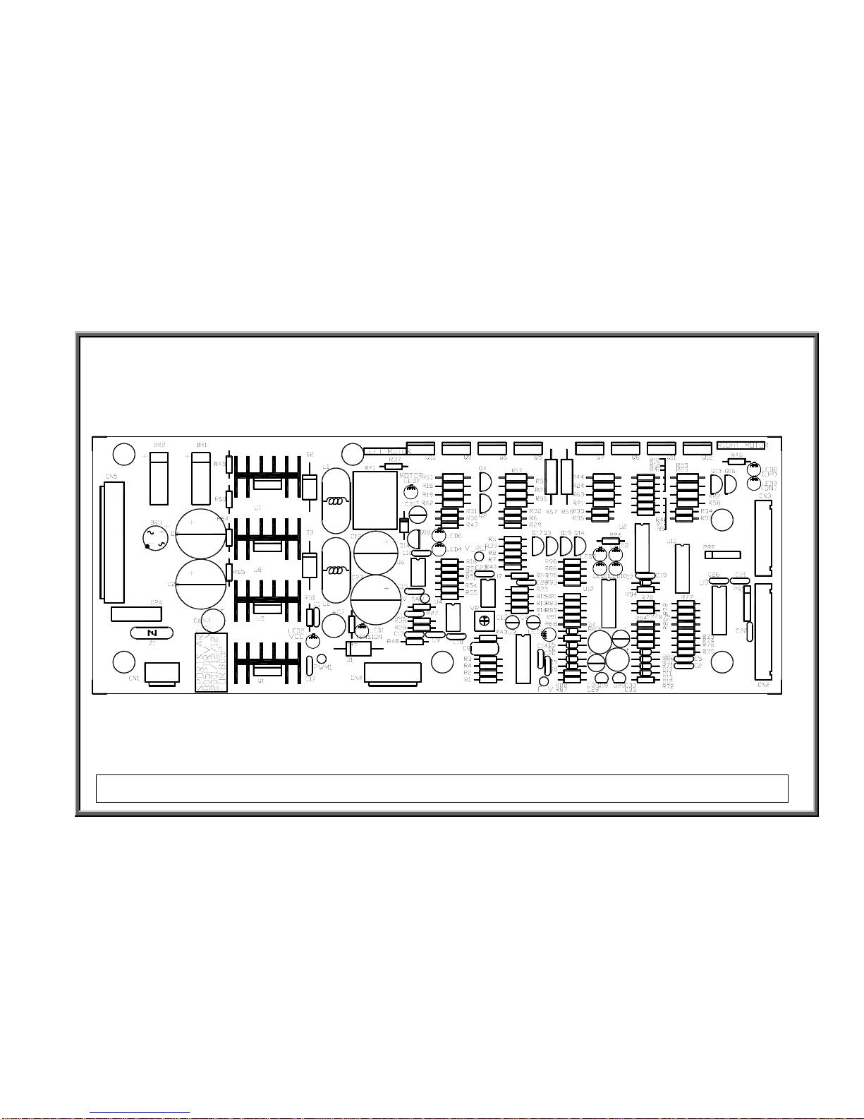
805P/807P Drive Board Component Illustration
DRIVE.02
Note: Subsequent revisions have changed the appearance of the drive board, which now has two layers.
 Loading...