

SportsArt Fitness 7100, S7100 Repair Manual

Version1: 12-26-01
Version 2: 10-26-04
SportsArt 7100/S7100
Stepper Repair Manual
SportsArt 7100/S7100 Stepper Repair Manual - Introduction
The SportsArt 7100/S7100 Stepper Repair Manual was made to help technicians in the field.
If you have suggestions or comments, please contact Bob Baumgartner by email at
bob@sportsartamerica.com
. T ha n k y ou !
Version 1: Dec. 26, 2001
Version 2: Oct. 26, 2004 – Updated to reflect changes in the S7100 stepper.
In the spring of 2004, the original 7100 stepper was updated. The display was changed and the
product name became S7100. Even though some operational steps may differ due to the display change
change, product functions are basically the same, and troubleshooting techniques are the same.
In this manual, notes were included to indicate places where the 7100 and S7100 differ.
In general, for troubleshooting purposes, 7100 and S7100 are the same.
0-0-0

SportsArt 7100/S7100 Stepper Repair Manual – Basic Illustrations
Table of Contents
Chapter 1. 7100/S7100 Stepper Basic Illustrations
1-1-1. Stepper Illustration (Assembled Unit)
1-2-1. Stepper Electronic Component Locations
1-3-1. Stepper Cable Connections
1-4-1. Stepper Display Board Cable Connections
1-5-1. Stepper Drive Board Cable Connections
1-6-1. Stepper Display Board Component Placement
1-7-1. Stepper Drive Board Component Placement
1-8-1. 7100 Stepper Display Overlay
0-0-1

SportsArt 7100/S7100 Stepper Repair Manual – Operation
Table of Contents
Chapter 2. Stepper Operation
2-1-1. Stepper Battery Operation (Continued through 2-1-5)
2-2-1. Stepper Generator Operation (Continued through 2-2-2)
2-3-1. Stepper Optic Sensor Signal Flow Chart (Continued through 2-3-2)
2-4-1. Stepper Resistance Operation Flow Chart (Continued through 2-4-3)
2-5-1. Display Keypad Function Flow Chart (Continued through 2-5-3)
2-6-1. POLAR Heart Rate Operation Chart (Continued through 2-6-2)
2-7-1. Stepper HTR Operation Flow Chart (Continued through 2-7-2)
2-8-1. Battery Recharge Flow Chart (Continued through 2-8-2)
2-9-1. CARDIO Board Power Supply Flow Chart (Continued through 2-9-2)
0-0-2
SportsArt 7100/S7100 Stepper Repair Manual – Testing
Table of Contents
Chapter 3. Stepper Testing
3-1-1. Drive Board Power Component Test (Continued through 3-1-2)
3-2-1. Drive Board Power VCC Voltage Test (Continued through 3-2-4)
3-3-1. Generator Voltage Test at the Drive Board (Continued through 3-3-2)
3-4-1. Optic Sensor Signal Test at the Drive Board (Continued on 3-4-2)
3-5-1. Resistance Voltage Test at the Drive Board (Continued through 3-5-2)
3-6-1. Battery Tests at the Drive Board (Continued through 3-6-2)
3-7-1. VCC Voltage Test at the Display (Continued through 3-7-2)
3-8-1. POLAR Heart Rate Test (Continued through 3-8-2)
3-9-1. Testing the HTR Board (Continued through 3-9-2)
3-10-1. CARDIO Board Test (Continued through 3-10-2)
3-11-1. Generator Test
3-12-1. Electro-Magnet Test (Continued through 3-12-2)
3-13-1. Optic Sensor Test (Continued through 3-13-2)
0-0-3
SportsArt 7100/S7100 Stepper Repair Manual – Basic Illustrations
Chapter 1. 7100/S7100 Stepper Basic Illustrations
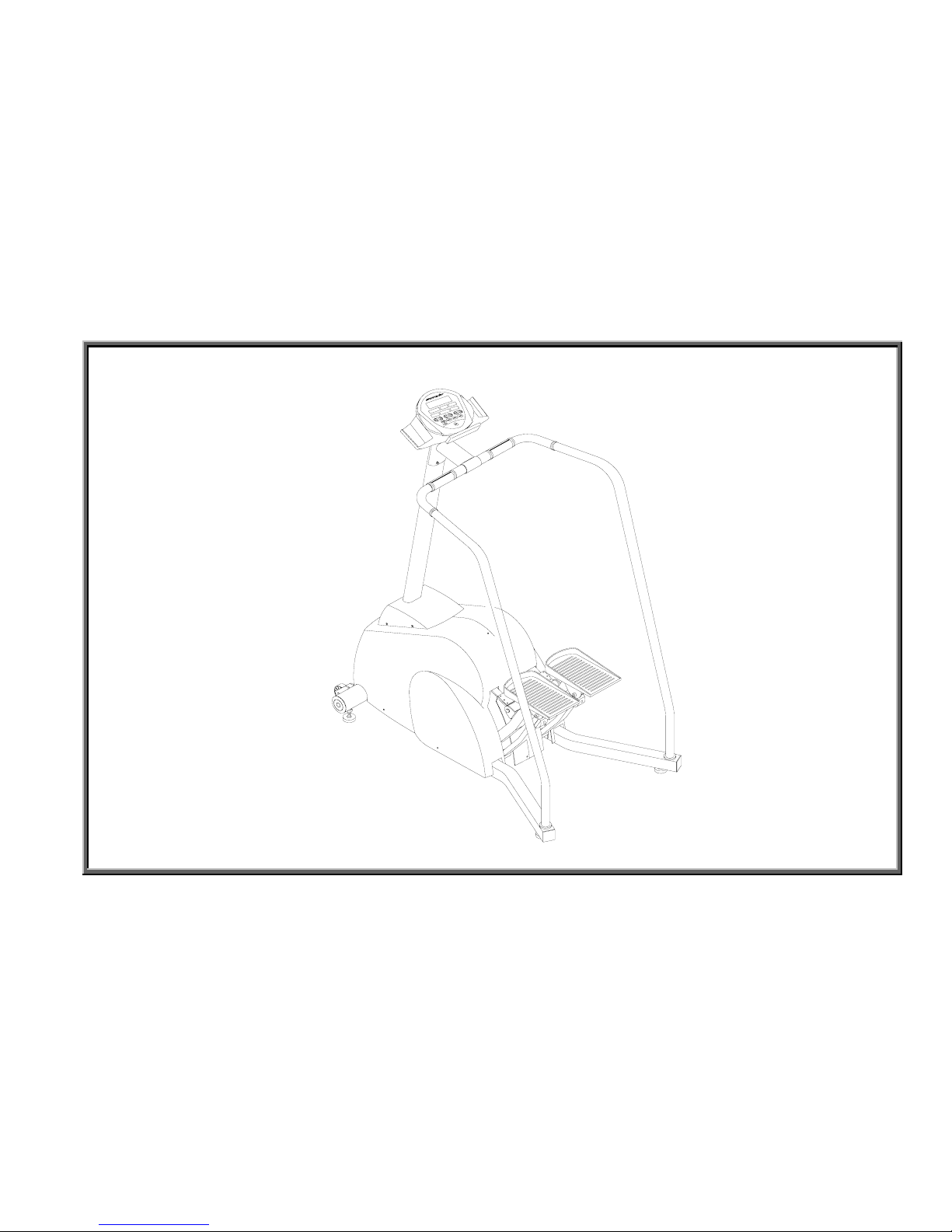
1-1-1. Stepper Illustration (Assembled Unit)
1-2-1. Stepper Electronic Component Locations
1-3-1. Stepper Cable Connections
1-4-1. Stepper Display Board Cable Connections
1-5-1. Stepper Drive Board Cable Connections
1-6-1. Stepper Display Board Component Placement
1-7-1. Stepper Drive Board Component Placement
1-8-1. 7100 Stepper Display Overlay
1-0-0
SportsArt 7100/S7100 Stepper Repair Manual – Basic Illustrations
Stepper Illustration (Assembled Unit)
1-1-1
Note: The original 7100
stepper is shown.The
display on S7100 is
different.
SportsArt 7100/S7100 Stepper Repair Manual – Basic Illustrations
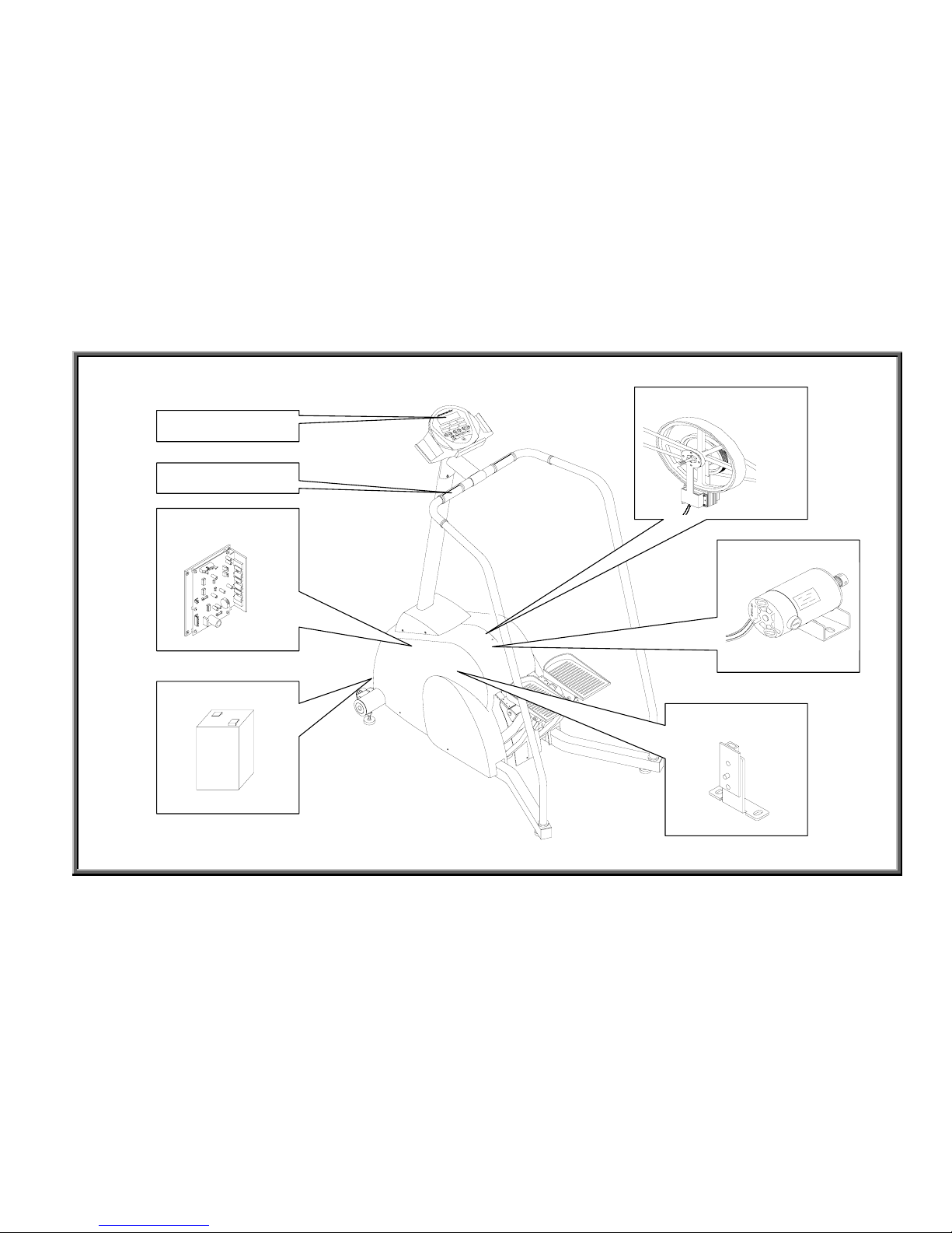
Stepper Electronic Component Locations
1-2-1
Display
HTR Handlebar
Drive Board
Battery
Magnet and Flywheel
Generator
Optic Sensor
SportsArt 7100/S7100 Stepper Repair Manual – Basic Illustrations
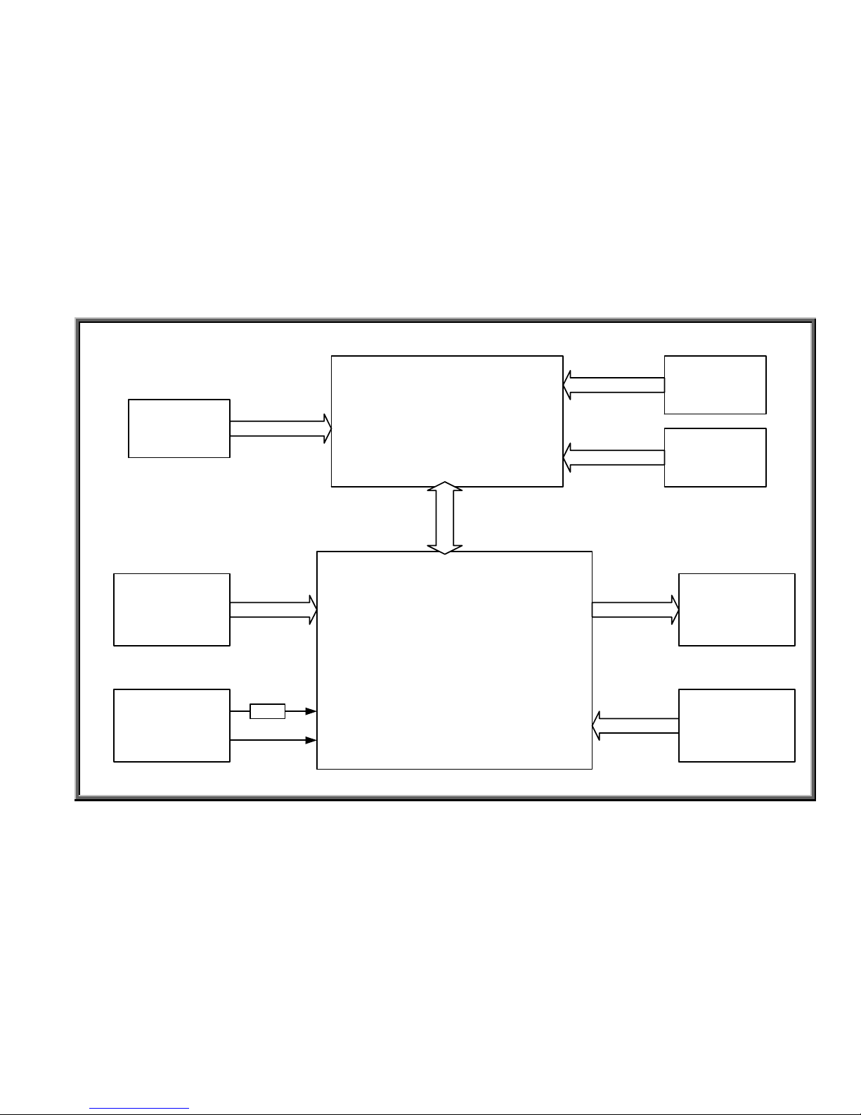
Stepper Cable Connections
Drive Board
Display Board
Generator
Battery
Magnet and
Flywheel
Optic Sensor
FUSE
HTR
Board
Soft Keys
POLAR
HR Board
2 PIN
16 PIN
2 PIN
3 PIN
3 PIN
3 PIN
1-3-1
SportsArt 7100/S7100 Stepper Repair Manual – Basic Illustrations
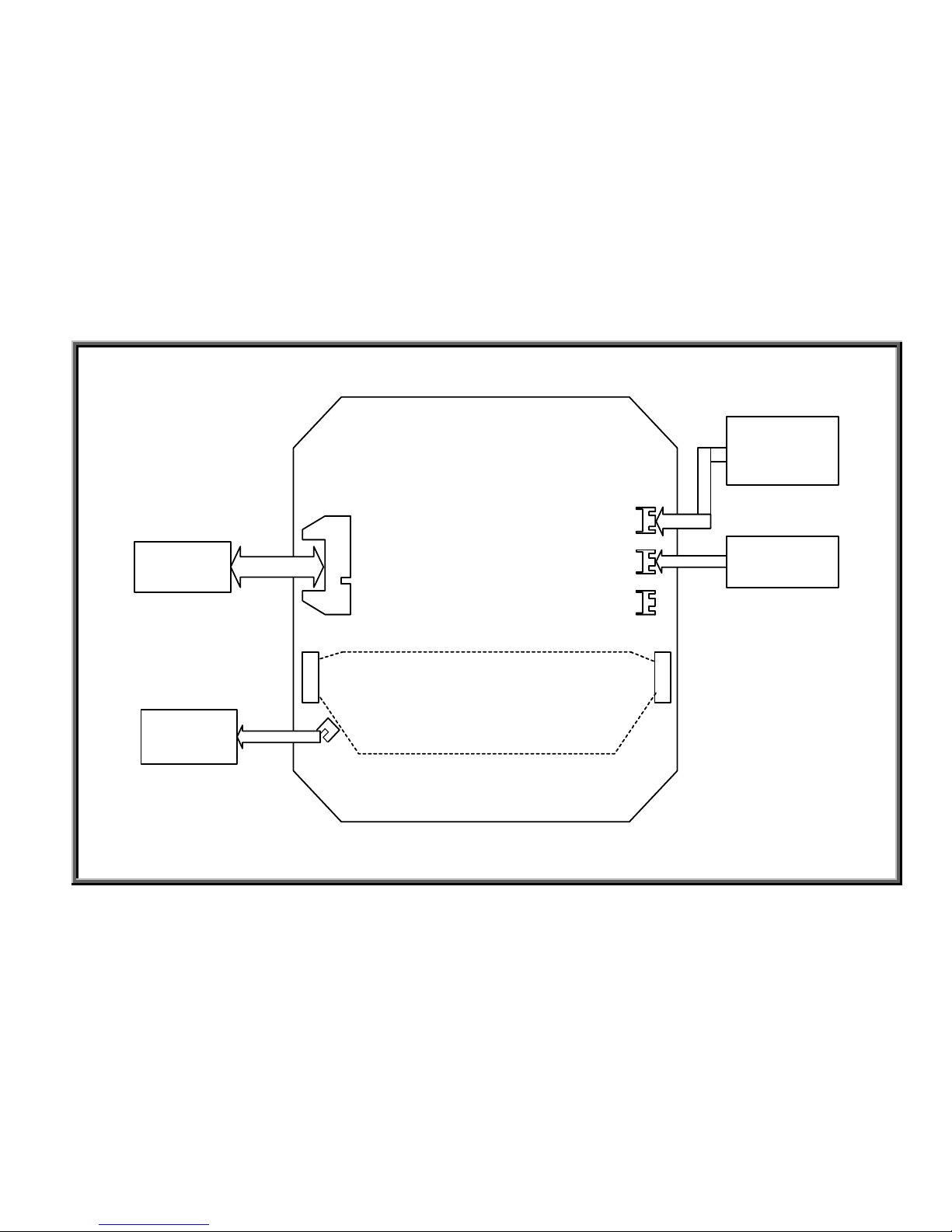
Stepper Display Board Cable Connections
J2
J4
J5
HTR Board
& HTR
Handlebar
POLAR
HR Board
3 pin cable
3 pin
Drive
Board
16 pin cable
Soft Keys
CNT3
CNT2
CARDIO
Board
2 pin cable
1-4-1
Note: S7100 cable
connections may differ.
SportsArt 7100/S7100 Stepper Repair Manual – Basic Illustrations
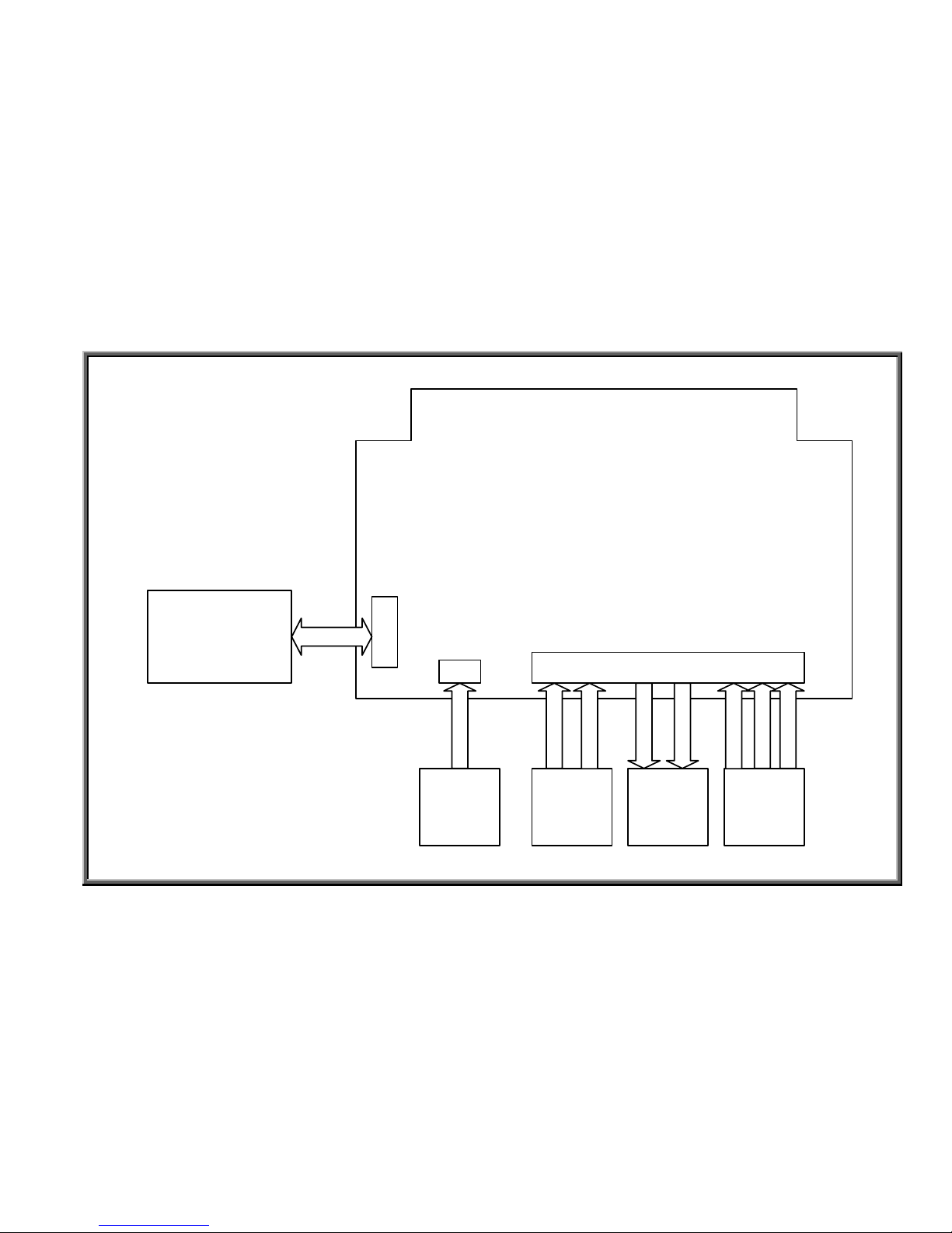
Stepper Drive Board Cable Connections
CN3
CN2
CN1
Display Board
Optic
Sensor
Generator
MagnetBattery
16 PIN
2 PIN
BLACK
WHITE
BLUE
BLUE
RED
YELLOW
BLACK
1-5-1
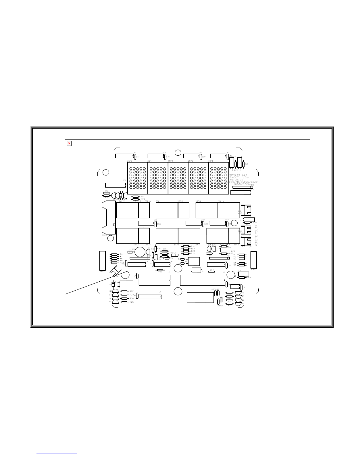
SportsArt 7100/S7100 Stepper Repair Manual – Basic Illustrations
Stepper Display Board Component Placement
1-6-1
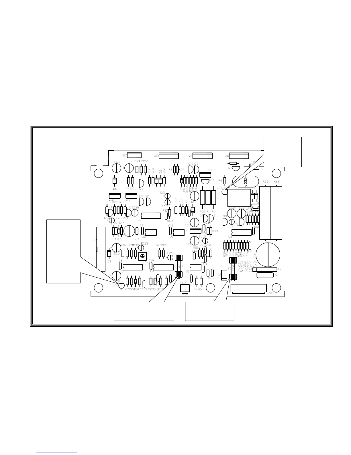
SportsArt 7100/S7100 Stepper Repair Manual – Basic Illustrations
Stepper Drive Board Component Placement
1-7-1
Battery Fuse Generator Fuse
Optic
Sensor
Signal
LED
Circuit
Protection
LED
Note: The
latest drive
board, V3.1, is
not shown
here. V3.1
came out
04-12-04. It
operates with
both 7100 and
S7100 displays.
Changing the
drive board
can alleviate
resistance
issues
associated
with earlier
drive board
versions.
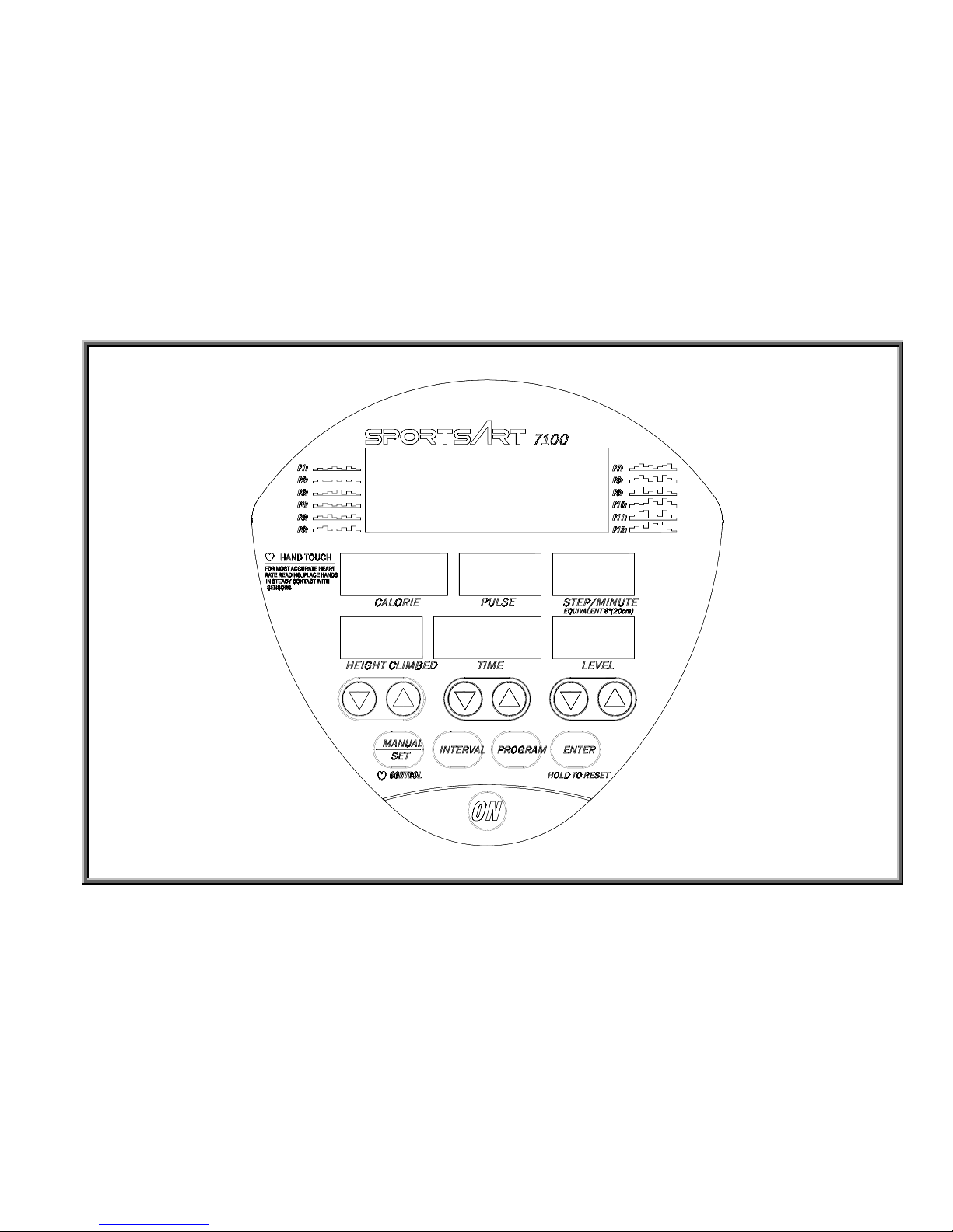
SportsArt 7100/S7100 Stepper Repair Manual – Basic Illustrations
7100 Stepper Display Overlay
1-8-1
Note: The S7100
display overlay is
different.

SportsArt 7100/S7100 Stepper Repair Manual – Operation
Chapter 2. Stepper Operation
2-1-1. Stepper Battery Operation (Continued through 2-1-5)
2-2-1. Stepper Generator Operation (Continued through 2-2-2)
2-3-1. Stepper Optic Sensor Signal Flow Chart (Continued through 2-3-2)
2-4-1. Stepper Resistance Operation Flow Chart (Continued through 2-4-3)
2-5-1. Display Keypad Function Flow Chart (Continued through 2-5-3)
2-6-1. POLAR Heart Rate Operation Chart (Continued through 2-6-2)
2-7-1. Stepper HTR Operation Flow Chart (Continued through 2-7-2)
2-8-1. Battery Recharge Flow Chart (Continued through 2-8-2)
2-9-1. CARDIO Board Power Supply Flow Chart (Continued through 2-9-2)
2-0-0
SportsArt 7100/S7100 Stepper Repair Manual – Operation
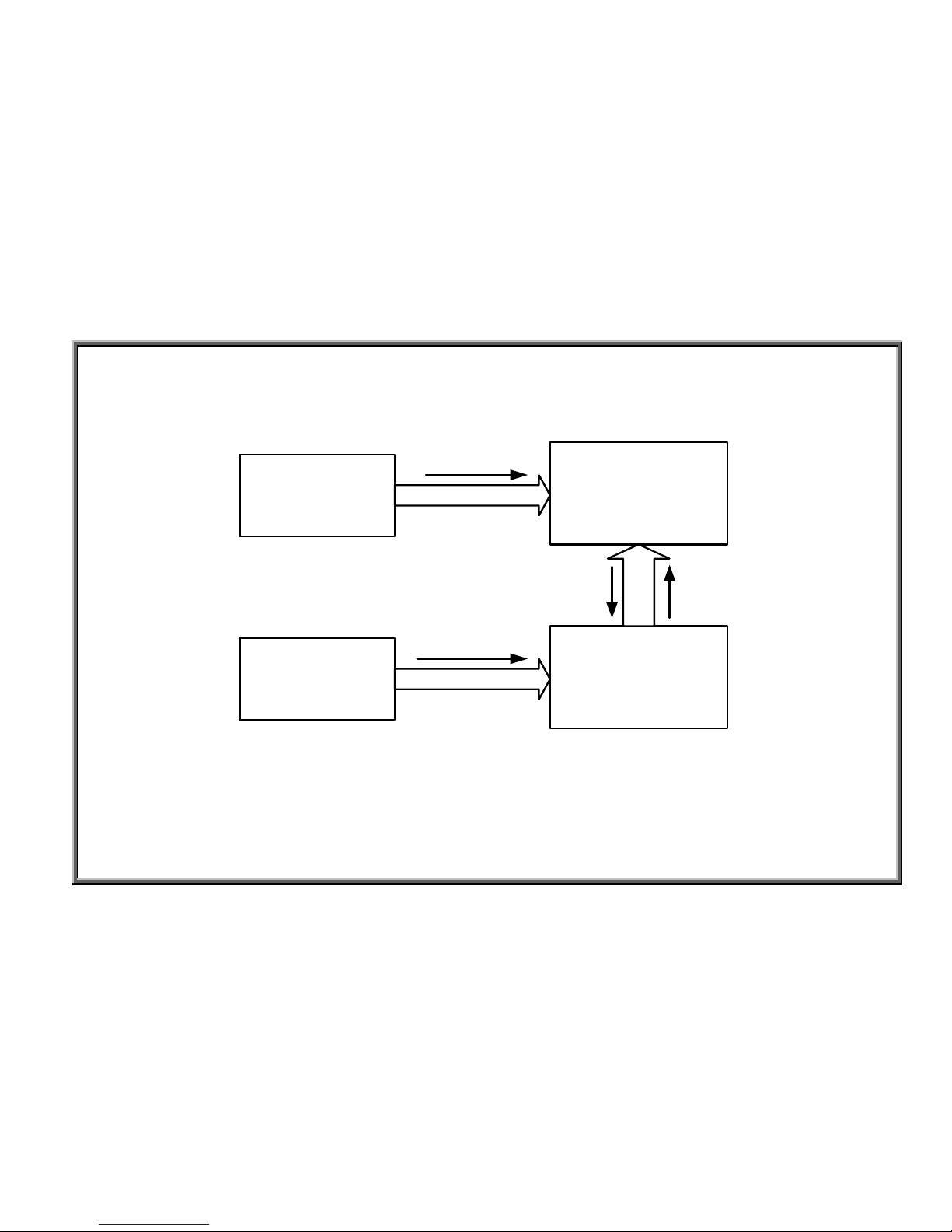
Stepper Battery Operation
1. Configuration
Display Board
Drive Board
Battery
2 pin
V
Soft Keys
VCC
16 pin
ON,OFF
ON
2-1-1
SportsArt 7100/S7100 Stepper Repair Manual – Operation
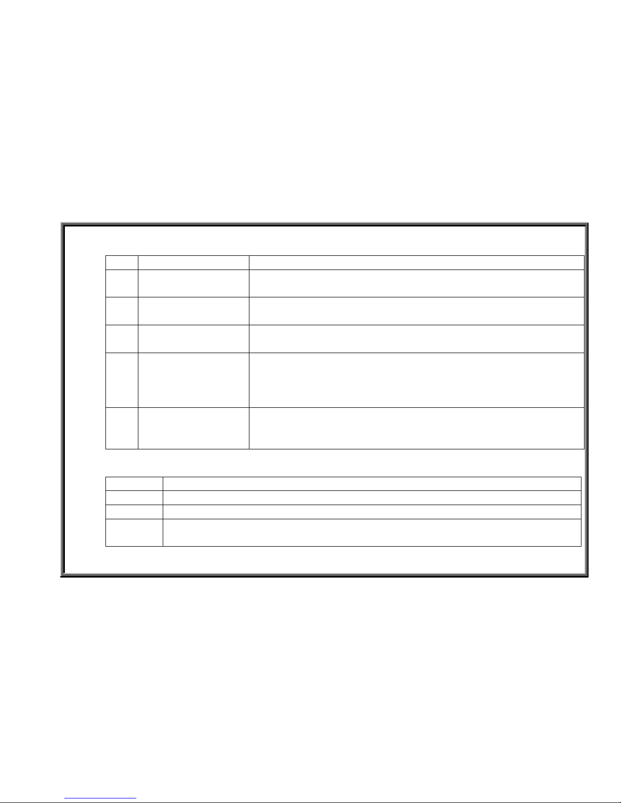
2. Battery Operation
Order
Component Operation
1 Battery 1. When no one is exercising on the stepper, the battery provides the
drive board with power, allowing the display to light.
2 Soft Keys 1. If the unit has yet to be turned on, pressing the “ON” key results in
a signal that prompts the drive board into action.
3 Display Board 1. When the “ON” key is pressed, the display board sends the “ON”
signal to the drive board.
4 Drive Board 1. The “ON” signal prompts the battery to emit voltage to the drive
board.
2. After stabilizing the voltage, the drive board provides voltage to the
display board.
5 Display Board 1. After the display board receives voltage,
2. The display beeps once, and the main (LED) window lights and
smaller windows show figures.
3. Procedure
Steps Operation
1 The display doesn’t light up.
2 Press <ON> key.
3
1. Display “beeps” once and the LED window shows “MAN’L”.
2. 8-segment LCD windows show “0000”.
2-1-2
SportsArt 7100/S7100 Stepper Repair Manual – Operation
Battery Switch Operation
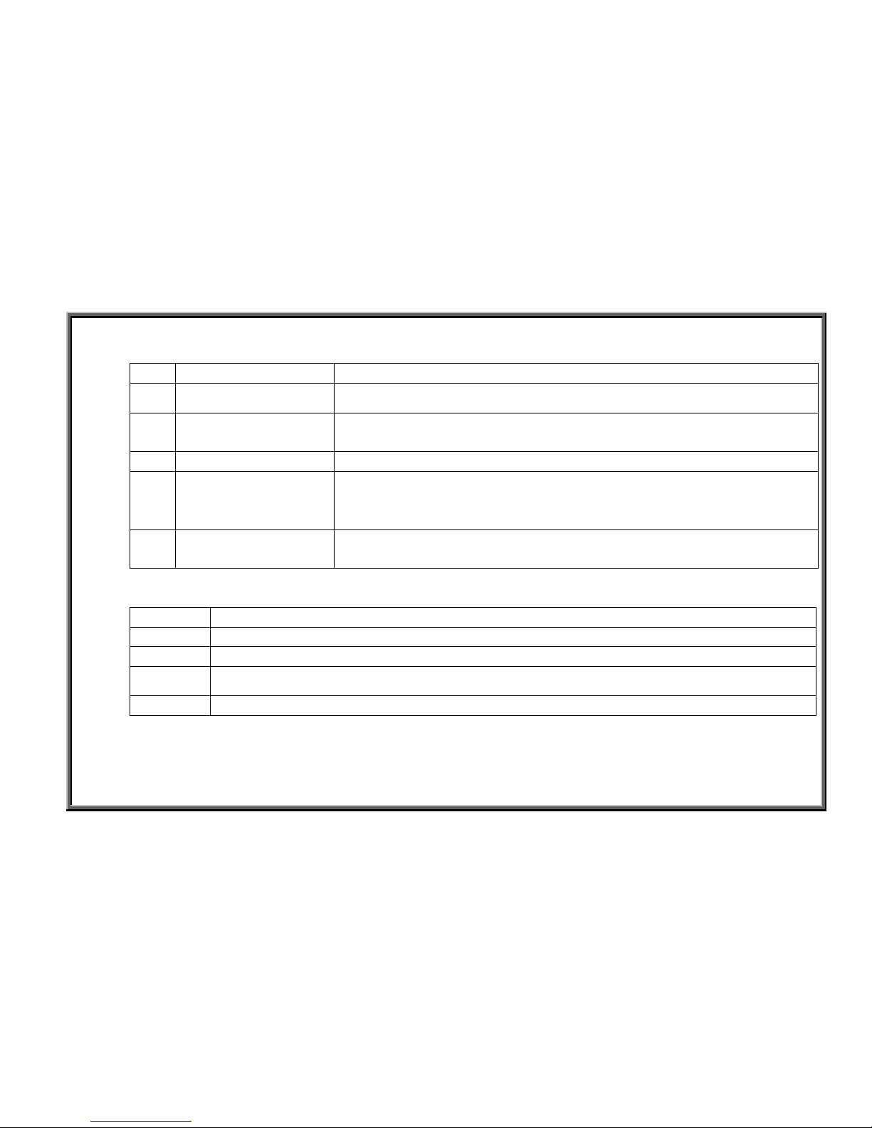
1. Battery Switch Operation
Order
Component Operation
1 Soft key
1. Press TIME<▼>+LEVEL<▼> to turn off the battery.
2 Display board 1. Display CPU reads the soft key OFF signal.
2. The CPU sends an OFF signal to the drive board.
3 16-PIN cable 1. The display board OFF signal travels the drive board.
4 Drive board 1. After the drive board receives the OFF signal, the battery voltage
turns off.
2. The drive board sends no voltage to the display board.
5 Display board 1. The display board doesn’t receive any voltage from the drive board.
2. The display shuts off; nothing lights on the display.
2. Operational Procedure
Step Operation
1 When the display turns on, it lights up.
2 When no one is exercising on the stepper,
3
Simultaneously pressing TIME<▼>+LEVEL<▼> keys,
4 The display shuts down; all windows become dark.
2-1-3

SportsArt 7100/S7100 Stepper Repair Manual – Operation
Battery Off Action – Automatic Shut Off
1. Configuration
Drive BoardDisplay
16 PIN
VCC,
CLK
OFF
2. Operation
Order
Part Operation
1 Display 1. The display board reads the optic sensor signal to distinguish whether
the unit is being used.
2. If there’s no optic sensor signal, the CPU sends the OFF signal within
two minutes.
2 16-pin Cable 1. The display board OFF signal travels the 16-pin cable to the drive
board.
3 Drive Board 1. After receiving the display board OFF signal, the drive board stops
sending voltage to the display. Display circuit voltage is named VCC.
2. No VCC voltage is sent to the display board.
4 Display 1. The display board doesn’t receive the any voltage from the drive
board.
2. The display board shuts off; Nothing lights up on the display.
2-1-4
SportsArt 7100/S7100 Stepper Repair Manual – Operation
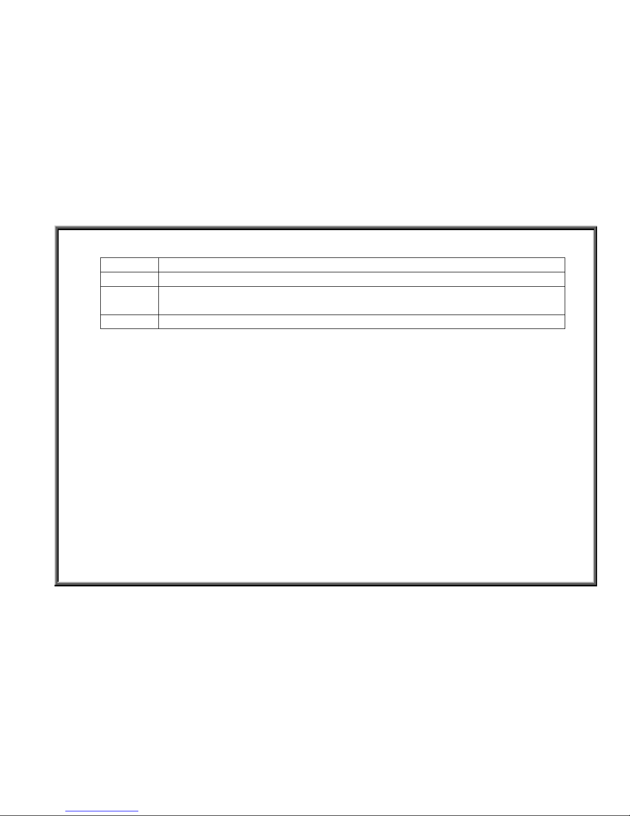
3. Procedure
Step Operation
1 The display lights up normally.
2 When no one is exercising on the machine, the display TIME window value doesn’t
change.
3 After two minutes, the display turns off; display lights extinguish.
2-1-5
 Loading...